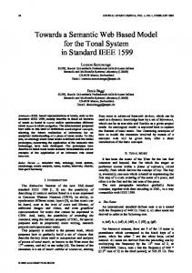
WCT is available for download in [30] and some features are illustrated in Figure 2.a. The WCT ..... XDoclet (competing to HBM and JPA). We compared first two ...
Towards a Web Modeling Environment for a Model Driven Engineering Approach Fábio Paulo Basso, Raquel Mainardi Pillat, Toacy Cavalcante Oliveira COPPE – PESC - Universidade Federal do Rio de Janeiro (UFRJ), Rio de Janeiro, Brasil {fabiopbasso, rmpillat, toacy}@cos.ufrj.br Abstract—one of the most challenges in Software Engineering is to reduce the applications development time. Although such reduction is a Model Driven Architecture’s (MDA) objective, its effectiveness in started from scratch applications is questionable. Generally, MDA approaches require a system model widely detailed whose production is time consuming. In this context, we present a MDA compliant approach based on rapid application prototyping. Our approach allows more reliable requirements gathering and validation because produces functional mockups. Keywords- MDA; GUI prototyping; mockup; MDD
I. INTRODUCTION Application prototyping is a good practice suggested and accomplished in the Requirements Analysis discipline that helps to reduce risks. Authors such as Pressman [24] argue that requirements elicitation is a hard task. Errors are very common when one performs this task, implying in rework. Authors suggest the usage of functional prototyping to achieve requirements reliability [6][24][27], although developing a functional prototype for a web application implies generally in the development of the whole functionality [1][6][13]. This means that such practice helps to reduce the risks of constructing wrong features. However, functional prototypes do not reduce significantly the rework if the prototype is incorrect. For this reason, Rivero et al. [13] and Jones et al. [29] conclude that companies are preferring to use sketching or mockup tools [12] that only draw User Interfaces (UI) without providing functional prototypes. However, this practice is not MDA compliant. In this context, we are working on an approach in which the mockup drawing leads to functional prototypes. Thus, this paper presents an approach originated from our experiences in MDD that aims at supporting more reliable requirements elicitation and validation to web applications. It uses GUI forms as the first models to obtain and validate software requirements. However, unlike other approaches, such forms are not result of a Model-to-Text transformation at the end of a transformation chain as is the common practice of many MDD approaches that support web applications [19][25][27]. Our solution uses GUI forms to generate UML model elements that afterwards are used to generate sourcecode. We have experienced good results by applying concepts of UI prototyping and MDD together and we will discuss them along the paper as well as research directions and limitations of our work. Next sections are organized as follows. Section 2 provides an overview of our MDD approach. Section 3 describes the
proposed tool support to develop web applications. Section 4 presents preliminary results from industry projects. Finally, Section 5 and 6 present related works, limitations and conclusions. II. A DSM ENVIRONMENT TO DESIGN WEB APPLICATIONS As recommended in the requirement engineering discipline, prototyping is a good practice. In this sense, we need to validate the system models using UI prototype simulations. Accordingly, to reduce the company’s staff re-work, one goal of the MockupToME is to facilitate the definition of a detailed PIM model and to simulate it. This means that, facing a client requirement elicitation, one want to delivery functionality that satisfies requirements as fast as possible. Our solution to acquire this goal is to design UML models and UI components with support for generative options for a specific requirement implementation. The usage of UI mockups reduced the team re-work as reported in a previous work [9] and we expected more productivity. But the mockup itself provides only more reliability regarding the client’s acceptance. This means that even adopting mockups, it is still necessary to modify the UML models and it requires UML Profiles domain experts. Besides, the UML tools provide few characteristics to change mockups and structural model elements. Therefore, we embedded into MockupToMe characteristics to simulate UI prototypes flows. Our tool is a Domain Specific Modeling (DSM) [21] designed to support the development of web applications with MDD practices. It supports automatic and guided transformations applied on mockups of UI forms such as exemplified in the activity diagram in Figure 1. It illustrates activities executed in a process similar to Rapid Application Development (RAD) lifecycles [24] in order to support rapid UI prototyping. Note that the source-code is generated only at the end of the activity diagram, meaning that simulations of client’s functionalities are realized by using UI model elements. Therefore, the source-code is generated only at the end of the “analysis and design” discipline in transition to the implementation discipline. The tool is useful in the beginning of a process iteration during the execution of the “requirements engineering” discipline. That is, before designing new requirements with class and use case UML diagrams at each requirement elicitation, the goal of the Requirement Engineer is to design mockups. The design is realized in synchrony with class diagrams, meaning that a modification in a user interface may
imply in modifications in a set of classes. The prototype model is also useful to apply changes in UML structural elements, such as classes, although it allows mainly the identification of details such as form properties, the sequence flow between UI forms (due to user interactions), and business rules. Thus, the tool is also a complementary to UML diagrams and sketching approaches that deal with web forms design. When mockups are ready for usability/flow test, the client performs the first validation. A simulation of the prototype model is executed when many UI options are available to support the same functionality, e.g. two options to support a search mechanism (we will discuss some options along the paper). Simulations provide information about the client’s acceptance regarding some features such as UI form fields, flows and strategies to refine UI and classes according a Domain Driven Design (DDD) approach [7]. When mockups fit client’s needs, UI components are transformed to other model application layers such as concrete UI components, controllers and DAO elements (still in model, not code). These model layers are refined by a Programmer and then a new usability test is required. After the functional prototype is approved, the source-code is generated, a Programmer performs the “implementation SE” discipline, a Tester performs the “Test SE” discipline and the procedure follows according a selected software process. III. TRANSFORMATION TOOL SUPPORT Work Case Toolkit (WCT) is an open-source toolkit that supports MDD [30]. Recently, the WCT project was embraced by the PRISMA research group [22] and, since then, it is getting ramifications to support particular research projects. One of research projects is the use of MDD practices to support web application development that is the focus of this paper. WCT is available for download in [30] and some features are illustrated in Figure 2.a. The WCT tool’s CORE implementation provides features to support MDD based mainly on the MDA approach [21]. It operates with XMI inputs exported in any version and tools listed in Section “Supported XMI” in [30]. The tool also supports a user interface to modify imported XMI elements and provides property editors, such as the one shown in Figure 3.b. In this case, property editor’s tabs group elements properties of the “Client” class. Despite enabling the edition of some UML element properties, WCT is not a UML modeling tool. It is a transformation tool that enables users to make model adjustments before applying some transformation. WCT also supports plug-ins as described in Figure 2.b and 2.c. Plug-ins are important to support the usage of DSMs, when the user needs to develop his/her own modeling elements extending those offered by the UML. Our metamodel dates from 2005 when “MDD patterns” were not well established (for example, in 2005 ATL was only a proposal and EMF had no free UML support). Currently, WCT is EMF compliant and we are adapting it to conform to MDT/UML2.
Figure 1. From client request to the source-code
WCT Core Features »It is developed with Java inspired in UMT; »UML metamodel (WCT-MOF API); »UML elements property editors; »Plug-ins support; XMI/UML
A
»Import XMI versions 1.0, 1.1, 1.2, 1.3 and 2.1; »Export XMI version 1.2; »DSML-UML conversions.
WCT Plug-ins: ...............
B
XML/DSMs
MockupToME »WCT-Service; »WCT-ORM; »WCT-Form Designer; »WCT-Action Profile; »WCT-Sample (M2C).
C XML .fomda
MDD Management »FOMDA metamodel (FOMDA API); »Features and transformation diagram; »Transformation chain; »PSM-to-Code (Java, C#, Python, PHP); »Java-to-UML rev. engineering. Figure 2. Main WCT Features
WCT has other open-source tools configured as plug-ins besides core features. The WCT core is an independent application and can be used by different domains although this paper is written for information systems. Figure 2.b illustrates features of the MockupToME and Figure 2.c illustrates a tool available to manage the model-driven transformation assets designed with the Features-Oriented Model-DrivenArchitecture (FOMDA) approach [30]. This approach is discussed in details in the works [8][9]. MockupToMe depends from the FOMDA approach.
The generated mockup has a mapped class “Client” (see the UML class diagram shown in Figure 3.a) that was previously imported by the WCT from an XMI file. The Client class is into a package as shown in Figure 3.a, meaning that MockupToMe groups elements according MVC design. Except for the model layer, other layers are not necessarily required as inputs to execute transformations for startup templates. Therefore, few domain classes are necessary to generate a simple mockup.
A. MockupToMe – a Sketching Support with UML Sketching in the context of web application development, also referred as mockup, is a technique of user interfaces (screens) drawing. Many tools support sketching (57 listed in wiki [12]) and provide drawing of UI components in independent and dependent formats of platform. Despite some tools are widely used in industry, they do not support the integrated development of UI components and UML artifacts that are crucial requirements to apply the MDA approach.
A
We have been using sketching tools to design layouts, but we do not use them to design UI forms. This is because sketching tools do not support the generation of UI source-code with bindings to the other layers that a web application requires (controllers and persistency are examples). The effort to put web application layers together discouraged us to use them in order to draw UI forms. Due to such reason, we developed our own sketching tool as illustrated in Figure 3. MockupToME takes as input a domain class diagram (a UML model). The classes do not require UML markups because these details will be provided by the Requirement Engineering with the assistance of wizards. Examples are functionalities available to apply details such as object relational mapping for the input entities shown in Figure 3.a. Transformations from Mockups to PIMs such as the generation of Controller classes taking the input shown in Figure 3.c are also supported and help in the “Analysis and Design” discipline. This is possible because mockups contain information about entities and their relationships as well as UI components contain stereotypes and tags; a detail that most mockup tools do not support [12]. For example, the reason why the buttons “Save” and “New” shown in Figure 3.a have different icons is that the first is stereotyped with .
Quick prototyping helping requirement analysis C B
D Figure 3. MockupToME Quick Prototyping Features
UML elements can be handled by UI components tree nodes as shown in Figure 3.b. These nodes can be used together with the drawing area shown in Figure 3.c. UI components may also be customized in property editors (Figure 3.d) such as in the tab “Mapping and Validation”. This tab enables component validation rules, e.g. if it is mandatory to persist data of type Client into a database.
Each UI component may receive an available transformer as a menu item if the component owns some tags and stereotypes. This constraint is defined in the model transformers that enable the refinement of the prototype: e.g. a button that must link to a “filter by” UI form assigns model transformers that generate some kinds of filter. We call the conjunction between the meaning of a tagged component (one stereotyped with ) and the options that fulfill this meaning (generate a “filter by” UI form or a “cascade filter”) as UI strategies. These are exemplified in Section C.
B. Metamodel and Extension Support MockupToME is a DSM tool to support web applications development. It extends WCT-MOF MDR [30] to support UI form sketching and DDD from UML classes received as input. A short part of a metamodel is shown in Figure 4. A complete metamodel and documentation are found in [20]. This metamodel was inspired in the Blankehorn’s work [16] because WCT adopts a UML transformation approach and we intended to reuse our legacy works [8][9]. Thus, UI prototypes support UML elements such as the Class and Property metaclasses to apply bindings between form fields and class properties. The Actor metaclass is also used to support view layer access constraints such as for an “Admin” actor to define that the “save” button is visible (see Figure 3.c).
The UI form shown in Figure 3.c is automatically generated by popup menu options shown in Figure 3.a. These options apply transformations to generate startup mockups templates.
Figure 4 presents metaclasses that support abstract and concrete components. Abstract component metaclasses are filled in gray color and are instances of ScreenLayoutModel
(called as abstract UI model). This metaclass is a kind of container element (analog to DIVs, Panels, etc.) and contains abstract components, instances of ScreenLayoutModelTuple (called as tuples). The Abstract UI model configures a layout where abstract UI tuples are located, such as: a) padding between the layout borders; b) the align axis (X or Y) where tuples are automatically sequenced; c) the distances between the tuples and their assigned labels; among other features to support quick form layout.
quick start of a prototype and to help in the PIM definition. DDD is used to drive the generation of a detailed PIM. UML elements such as classes are generated from the UI forms with more elaborate techniques based on DDD and Rapid Application Prototyping (RAP). It is possible to generate multiple versions of an abstract UI form for a particular use case scenario that requires operations such as Register, Read/filter, Update, and Delete (CRUD). This is useful to the Requirement Engineering to present more than one option to the client during the requirement elicitation. By this reason, firstly we perform a simulation of the alternative screen flows and afterwards we generate web forms according the options selected by the client. Therefore, the client may choose between many prototypes the one which best fits his/her needs. Abstract UI components support the usage of tags and stereotypes. This UML Profile extension mechanism is used to develop functionalities in MockupToMe faster than by programming it in our DSM metamodel. This is also a legacy approach, since we started firstly using UML UI components and after we decide to develop a DSM support. Therefore, to reduce the evolution cost of this plug-in, we first work with annotated UI components and then modify the UI metamodel to support new features. We follow a method regarding tool evolution: when annotations prove to be an important feature, then the tool’s core is modified. As our tool does not support control for metamodel evolution, we are planning integration with the ongoing approach presented in [4].
Figure 4. Part of the UI metamodel
A UI tuple may be used to draw any ScreenArea subtype element such as a button, a label, a table or a dialog. The type of a tuple is defined in the property type of the AbstractLayoutModelTuple metaclass (a textual value). This means that such property may receive any value from the name of a concrete Java class that is instance of the ScreenArea metaclass. To support extensions, a Java class checking is performed during the classes loading by the WCT in order to identify and load external metamodel classes such as a concrete UI metaclass. This means that any screen area can be provided as an extension of our UI metaclasses by extending the ScreenArea element. Abstract and concrete components have different purposes. The first ones are used to support quick prototyping and focus on the generic representation of UI components. Concrete components focus on flows, events and properties of a specific kind of UI component such as OnLoad that is supported only in few web AJAX technologies. Abstract UI may be transformed to a simpler UI source-code because it is a general purpose UI component and concrete UIs can be refined to provide all necessary information to generate platform specific UI sourcecode. In this sense, concrete UI components may receive specific events supported only for a specific target technology. C. Startup Templates and Guided Strategies MockupToME provides several strategies to generate abstract UI forms. Strategies have two purposes: to provide a
Annotations are used on UI components, but the most of them are defined automatically by a transformation. For example, consider an abstract UI that represents a UI component such as a container. This element is instance of ScreenLayoutModel metaclass (Figure 4). Such metaclass does not support the definition of a property that indicates if it is a FORM web component because it was designed to represent only generic UI component properties. In order to express it, the abstract UI component assigns a stereotype that is added during startup template generation or modified manually by the Requirement Engineering during the mockup refinement. Therefore, despite the tuple to have few properties, we may express much more information using UML annotations. Mockup refinement occurs with support of guided strategies. Assume the one-to-many relationship between a Client class and the Category and CreditCard classes, shown in Figure 2.a. When refining the UI form for the “register a client” functionality, each association may be differently handled using strategies to support a particular user interaction. To put some items of the Category entity inside the Client entity, one may prefer the usage of a strategy one-to-many called “SourceTarget master-detail”, as shown in Figure 5 and titled as “Category Preferences”. For CreditCard, one may opt by the default “Table master-detail” strategy shown in Figure 5 and titled as “Credit Cards”. Strategies are available as transformers. To convert one of them to another is an easy task since it is available in popupmenus executed over each of the elements of designed mockup shown in Figure 5. One can undo transformations to decide what strategy best fits to express a specific part of
functionality. In other words, the Requirement Engineering may alternate between strategies for each association owned by Client entity. A complete reference of Startup templates and Guided Strategies is presented in details in manual and tutorials section [20].
Figure 5. Two Guided Strategies for One-to-Many MasterDetail
Regarding previous experiences in the usage of MockupToMe [9], guided strategies enable the generation of web application layers that required less changes than when the Adapit’s staff used only UML model elements as input for transformations. The alternation between strategies implies in totally different model element layers generated at the end of the “analysis and design” discipline. The operations of a DAO layer generated for the first strategy (Category Preferences) use different parameters and implementations than for the second one (Credit Cards). Therefore, strategies enabled a more feasible UML model input than with our first experiences in MDA. D. From Mockups to PIM MockupToMe focuses on the relationship between UML model elements and UI components. It enables the synchronization between UI sketching and UML application models. During sketching shown in Figure 5, a new component added into “Client (Master)” is asked for inclusion as a property in the Client class, as well as a new added column inside the table shown in “Credit Card” is asked to add a new property inside CreditCard entity. This is also valid for associations that can be added during prototyping. Figure 6 (bottom) exemplifies two strategies used on oneto-one relationships. They are containers that have information about associations in the Client class regarding ClubBonus and UserData entities. The “User data” container relationship was expressed as an “embedded form” strategy, meaning that an object of type UserData is persisted in the same moment that Client is persisted. The second strategy is the association
between Client and ClientBonus that enables the user to filter items using the search form shown at the top of Figure 6 and to select one item to merge with the client association.
Figure 6. One-to-One Master-Detail with Find Strategy
Mockups can be used for transformations. One can transform those mockups shown in Figure 5 and 6 to a UML class that expresses business logic. This means that all strategies used in mockups imply in the usage of different transformations. For example, both one-to-one strategies imply in two additional parameters into an operation of a ClientDAO class that handles business logic for the DAO layer. Assume that the button named “Save” shown in Figure 5 implies in a transformation that generates an operation named “save”. Therefore, the possible operation generated in a DAO layer from this mockup to a UML class may be: + save( cli: Client, cb: ClubBonus, ud:UseData). After startup and guided strategies are used and assuming that the Requirement Engineering receives a client approval, the prototype is refined by a Programmer. The refinement is performed manually and also with help of transformations (see MockupToMe documentation for more details [20]). It shows four startup templates available to generates CRUD forms, four strategies to support 1..1 relationships and four strategies to support 1..* relationships. Some strategies have sub-strategies such as two to support search/filter actions and other strategies to support specific UI components such as trees and tables. Another kind of transformer is available to generate UI components, from those abstract UIs shown in Figure 5 and 6 to concrete components. It assigns features such as: position (absolute or relative), layout managers, events, dialog messages, general form field validations converted to some regular expression, etc. This means that only concrete components may receive information about layout managers that satisfy a specific UI technology such as Java Swing or web jQuery.
In our experiences, the programmer also documents all required steps to modify existent source-code in order to support the new code generation. He/she performs a manual round-trip to bring differences from source-code to the model. We have experienced that to generate source-code for “isolated” modules mitigates this task because our tool enables to generate many source-code parts that do not require programmers hands-on. Kelly and Tolvanen [26] wrote that DSM enables the full code generation for what is modeled on a tool designed to attempt for a specific domain: to every modification on a model, the source-code must be generated again. Note that authors do not inform that 100% of the application’s code is generated, but that it is possible to generate 100% of a small modeled part. This is our goal, despite our best results turns around 65% of generated sourcecode. The result of a mockup is a fully testable PIM prototype that can be transformed further to source-code by using PSM model transformers. We have experienced some practices during the development of specific parts of web applications using MockupToME and perceived that an effort that leads to less source-code modifications can bring better result in productivity. In this sense, round-trip serves only to maintain the consistency between code changes and model elements that are not generated by the tool. Programmers do change many parts of a generated source-code, but the round-trip focuses on non-generated source-code classes. E. Transformation from PIM to PSM Currently, MockupToMe supports the generation of PIM models decorated with UML stereotypes and tags coming from WCT ORM Profile and WCT Service Profile (includes Action Profile) [20]. This allows one to map the following details in a PIM model: 1) Model-Entity layer with support of Object Relational Mapping (ORM) details; 2) Controller-Business layer with support for transactions involving the Service/Business layer and calls for a remote access layer; 3) Controller-Persistency layer with Data Access Object (DAO) pattern to support persistency details; 4) Controller–Actions layer to handle UI events; 5) View layer that is handled entirely with MockupToMe. Figure 7 depicts all technologies that M2T transformations have been applied to generate PSMs. Note the dotted squares; they represent alternative technologies for web applications described in Section IV. These alternatives are handled in the WCT tool with support of the FOMDA approach which applies the product line architecture to the model transformer domain [8]. This means that by changing some configurations based on Features Model [3] and domain engineering practices, a transformation chain that runs the correct sequence of transformers is achieved. This approach has been used since work in [10]. IV. APPLICATION IN INDUSTRY PROJECTS The WCT tool has been used since 2007 in the Adapit Soluções em TI, a Brazilian software development company, to create web applications with Java programming language. The company has used the tool to assist the development of three
industry projects: 1) a web/desktop application to online auction with support to ERP and CRM functionalities (system with 656 classes and 190 JSP files), developed by the company’s team; 2) a web and desktop application used internally to support trainee/teaching management (system with 789 classes and 149 JSP files) developed by the firm’s founders; 3) a web application with focus on management of financial support for innovation projects whose the experiences were reported in [9].
Figure 7. MockupToME model-to-text transformers
The third application was just assisted by the Adapit’s team that participated as tool provider. In all projects the WCT tool was successfully used to generate code for graphic user interface layer (desktop and web), data access layer, entity layer, integration/remote layer, xml configuration files, text files, Java classes, data base scripts, models, etc. The first mentioned application had the following configuration of technologies (target platform): Hibernate, JPA, jQuery, JSTL, Swing, PostgreSql, Apache commons validation, and Springframework. The following technologies were changed across projects: a) we used in the second project HBM files to apply Hibernate mappings (ORM) and in other projects we used JPA; b) The first two projects used Dojotoolkit API as web technology to write rich user interfaces and the last project used jQuery. Other target technology used as ORM was XDoclet (competing to HBM and JPA). We compared first two projects, both they used different versions of MockupToMe. Applications are being developed slightly faster with support of this tool than without it, as reported in [9]. The generated code in the second project required 10% less modifications in the source-code than it was required in the first project. Note that such modifications have no relation with requirement elicitation, but with the richness of the generated source-code. We classified such difference as an improvement of the transformers’ result quality and also as a result of the use of new guided strategies. We also reduced the time between sprints for one week in the second project (we used four weeks in the first one), what contributed to less modifications. As the second software was used internally by the company, we can consider that the requirement elicitation was more feasible in the second application than in the first. Therefore, no stronger conclusion from MDD practices
presented in this paper can be tacked from these experiences in the industry.
tools. This also means that our tool requires less time of a UML specialist to design the details of a web application.
The development of the third project, reported in [9], led us to observe about requirement elicitation. We realized fewer modifications related to mockups and UML models according client expectations than we measured during the development of the online auction application. Note that both applications were developed with similar technologies, but by different teams and using different versions of MockupToMe. Therefore, these data cannot be used as a parameter for comparison. But the newest version of this tool (related to new guided strategies) implied in lower number of modifications than we observed in our own projects developed before the third project.
Our approach has some benefits compared to the related works. It has less dependency from a UML Profile domain expert because the PIM is composed during sketching. As reported in [9], this approach enabled a company to observe a rapid development of web applications after a period of learning. In this sense, other observed benefits are:
Before the three mentioned projects that used our tool, we developed two other applications with only support of modelto-code transformations. In one of them we needed to stop the usage of MDA because the team lost the UML Profile specialist. This experience showed us that our MDA approach cannot be successful used without a UML Profile specialist. This is valid even in our current practices, where MockupToMe is used to generate PIM and less intervention is required of this specialist. An expected result of our work is less dependence of a UML Profile specialist and this result was achieved. But it still does not satisfy our expectations because some model details need stereotypes and tags. Thus, we expect that in future works this dependence impacts less on the usage of our MDD practices. Such analyses do not serve to compare projects practices and tools. The unique purpose is to report that with the MockupToMe support we have achieved better results than without using it. As we did not apply a qualified study about our practices and tool during the industry projects, an experimental study that leads to stronger conclusions is necessary. V. RELATED WORK Many MDD tools support the generation of UI for web applications [1][6][15][19][27], but they require a very detailed UML model as input. Examples of such input are use case diagrams, class diagrams and activity diagrams, all they assigned with plain UML Profiles tags. MockupToME, on the other hand, proposes to follow an opposite direction. Its approach starts from a simple input, such as a domain class diagram without tags and stereotypes. UML profile details are further generated using wizards, transformations and manual configurations assisted by the tool. Regarding this point, our approach is singular because we use mockups to drive the “analysis and design” SE discipline generating automatically or by guided way a platform independent model (PIM). In MockupToMe, UI forms are used as input for model transformers to assist the generation of other elements represented in the MDA’s PIM vision. In other approaches [1] [6][15][19][27], these PIM elements are UML classes, activities and use cases that serve as input to transformation tools to generate source-code. A PIM in MockupToMe is a reduced domain class diagram. This means that our tool requires input data in simpler format than is required by related
1.
2.
3.
4.
5.
Our approach aims at simulating user interactions in the modeling phase, similarly as tools in [5][6]. Differently than these related works, MockupToMe simulations occur in two environments: 1- into the tool (performed by the Requirement Engineering), offering to the client many mockups to support a same functionality; 2- when the Programmer, still in model, enables to the client a test of usability using a web browser. Source-code is generated only after success on simulations; Prototypes help to identify client’s needs during requirement elicitation. This conclusion is the same achieved by works in [6][13][18]. Moreover, we have experienced that the client discovers more necessities in simulating a UI prototype; Using abstract UI components helps to capture the application’s essence avoiding troubles with widgets’ specific details. Regarding this feature, we did not find in the literature a similar work because the existent ones use a single tier for UI components; The usage of legacy MDA transformers. Another tool that supports web applications is WebML[25], although it does not use or extend UML as MockupToME does. Our approach enables the use of legacy MDA model transformers because, despite it is a DSM environment, it is also a UML Profile based approach. Our work applies DSM approaches principles [20], focusing on the design of small parts of a system. The generated code keeps in isolated modules from the code programmed manually (that cannot be generated using the tool). Modifications in the structure of the generated code must be applied inside the MockupToMe and afterwards the source-code must be generated again.
VI. CONCLUSIONS, LIMITATIONS AND FUTURE WORKS MockupToMe/WCT has been used in three industry projects applying the practices described in this paper. Our experience in these projects leads to observe that adopted practices may be a possible solution to reduce the number of modifications between sprints after the source-code generation; despite we have not collected metrics that would lead to stronger conclusions. This is the main restriction of our work because without measures to compare MDA approaches we do not conclude which of them is the best regarding productivity, facility, less modifications in source-code, and so on. As a future work we are planning a controlled experiment to achieve stronger conclusions. Such experiment will be performed in the academy, by the PRISMA research group [22]. Its results will be used to direct improvement works of the MockupToMe to assist web application engineering. After this
experiment, we will evaluate if a richer set of functionalities and mockup strategies are necessary as well as new model transformers to support mockup-to-PIM and PIM-to-PSM transformations. Our work presented model transformers that support rapid application prototyping. We denominate them as startup templates and guided strategies that help Requirement Engineers to design UI forms that fits to client needs. Despite our tool help in generation of some UML model elements such as MVC classes, only a limited number of strategies are support by our tool. Therefore, a study aiming to identify other strategies is required to help Requirement Engineer to generate web UI forms. Another limitation is that we have not compared our work with other approaches that also intends to generate source code for web applications. A limitation of the tool is that it do not support drawings facilities provided by many mockup tools. The tool is focused on strategies to generate UIs and UML model elements and was developed to support the needs for a specific software company. This means that the tool was not exhaustively tested and the solutions may not be generable for any company that develops web applications. Also, currently is difficult to draw UIs without the support with transformations. Therefore one must not use the tool to design rich layouts. ACKNOWLEDGMENT Thanks are given to CAPES and CNPQ for supporting this project. REFERENCES [1]
[2]
[3]
[4]
[5]
[6]
[7] [8]
[9]
A. Kraus. Model Driven Software Engineering for Web Applications. Dissertation, LMU München: Faculty of Mathematics, Computer Science and Statistics, 2007. B. Hailpern; P. Tarr. Model-driven development: The good, the bad, and the ugly. In Proc of IBM Systems Journal, Vol 45, NO 3, 2006, pp. 451 – 461. C. Kang, S. Kim, J. Lee, K. Lee, E. Shin, and M. Huh. FORM: A feature-oriented reuse method with domain-specific architectures. Annals of Software Engineering, V5, Balzer Science Publishers, 1998, pp. 143-168. C. K. F. Corrêa, T. C. Oliveira, C. M. L. Werner. An Analysis of Change Operations to Achieve Consistency in Model-Driven Software Product Lines. In: Proc. of 15th International Software Product Line, 2011. C. Stary. Contextual Prototyping of User Interfaces. In Proceedings of the 3rd conference on Designing interactive systems: processes, practices, methods, and techniques (DIS '00); 2000. pp 388 - 395. D. A. Nunes; D. Schwabe. Rapid Prototyping of Web Applications Combining Domain Specific Languages and Model Driven Design. In Proceedings of the 6th international conference on Web engineering (ICWE 2006). pp 153 - 160. Eric Evans. Domain-driven design: tackling complexity in the heart of software, Addison Wesley, 2004. F. Basso, T. Oliveira, L. Becker. Using the FOMDA Approach to Support Object-Oriented Real-Time Systems Development; In Proc. of ISORC 2006. F. Basso, R. M. P. Basso. Um Relato de Experiência no Desenvolvimento Ágil de Software com a MDA. In First Brazilian Workshop on Model Driven Development (I BW-MDD), 2010, Salvador – Bahia, Brazil. In Portuguese.
[10] F. Basso, R. M. P. Basso, T. C. Oliveira, S. L. Assi. FOMDA ML: Uma Linguagem para Especificação de Transformadores de Modelos na MDA. In Rapid Application Development Workshop (WDRA), 2009, Ouro Preto – Minas Gerais - Brazil. In Portuguese. [11] G. Boch, J. Rumbaugh, and I Jacobson, The Unified Modeling Language: User Guide, Addison-Wesley- Longman, 1999. [12] GUI Prototyping Tools. March 2012. Available at http://c2.com/cgi/wiki? GuiPrototypingTools [13] J. M. Rivero; G. Rossi; J. Grigera; J. Burella; E. R. Luna. From Mockups to User Interface Models: An Extensible Model Driven Approach. Springer-Verlag Berlin Heidelberg 2010, In ICWE Workshop, 2010, pp 13-24. [14] J. Stocq; J. Vanderdonckt. A Domain Model-Driven Approach for Producing User Interfaces to Multi-Platform Information Systems. In Proceedings of the working conference on Advanced visual interfaces (AVI '04). 2004. pp 395 - 398. [15] J. Vanderdonckt. A MDA-Compliant Environment for Developing User Interfaces of Information Systems. Springer-Verlag Berlin Heidelberg 2005, In CAiSE 2005.pp. 16 – 31. [16] K. Blankenhorn. A UML Profile for GUI Layout. Master Thesis. 23 May 2004. Universisty of Applied Sciences Furtwangen. Department of Digital Media. 2004. [17] L. Dannecker; M. Feldmann; T. Nestler; G. Hübsch; U. Jugel; K. Muthmann. Rapid Development of Composite Applications Using Annotated Web Services. Springer-Verlag Berlin Heidelberg 2010, In ICWE 2010 Workshops, LNCS 6385. pp 1-12. [18] M. Elkoutbi; I. Khriss; R. K. Keller. Automated Prototyping of User Interfaces Based on UML Scenarios. In Automated Software Engineering, 2006, pp 5 - 40. [19] MDArte Wiki – Hosted as a MDA Brazilian Government Initiative for Public Software Repository. Available at http://www.softwarepublico.gov.br/dotlrn/clubs/mdarte/xowiki/. [20] MockupToME Project Description. March 2012. Available at http://prisma.cos.ufrj.br/wct/projects/mockuptome.html [21] Object Management Group MDA Specifications. October 2004. Available at http://www.omg.org/ /mda/specs.htm [22] PRISMA Research Group – COPPE - Federal University of Rio de Janeiro (UFRJ). March 2012. Available at http://prisma.cos.ufrj.br/pt/home [23] R. S. S. Filho; F. Bronsard; W. M. Hasling. Experiences Documenting and Preserving Software Constraints Using Aspects. In Proceedings of the tenth international conference on Aspect-oriented software development companion AOSD’11 Companion, March 21-25, 2011, Pernanbuco, Brazil. [24] Roger S. Pressman. Software Engineering - A PRACTITIONER’S APPROACH. Fifth Edition. ISBN 0073655783. 2001. [25] S. Ceri; P. Fraternali; A. Bongio. Web Modeling Language (WebML): a modeling language for designing Web sites. Computer Networks Volume 33, Issues 1–6, June 2000, Pp 137–157. [26] S. Kelly, J. P. Tolvanen. Domain Specific Modeling: Enabling Full Code Generation. IEEE Computer Society - John Wiley & Sons. 2008. [27] S. Kavaldjian. A Model-Driven Approach to Generating User Interfaces. In Proceedings of the 6th joint meeting of the European software engineering conference and the ACM SIGSOFT symposium on The foundations of software engineering (ESEC-FSE '07). pp 603-606. [28] V. E. S. Souza; R. A. Falbo; G. Guizzardi. A UML Profile for Modeling Framework based Web Information Systems. Proceedings of the Workshop on Exploring Modeling Methods for Systems Analysis and Design (EMMSAD'07), Trondheim, Norway. pp 149 - 158. [29] W. Jones, J. Spool, J. Grudin, V. Bellotti, M. Czerwinski . “Get Real!” What’s Wrong with HCI Prototyping And How Can We Fix It?. In proceedings of CHI EA, extended abstracts on Human factors in computing systems (CHI EA '07), 2007. pp 1913 - 1916. [30] Work Case Toolkit 0.4 beta 1. March 2012. Available at http://prisma.cos.ufrj.br/ wct/index.html