19 (Partial) Domain Model for Invoicing System . . . . . . . . . . . . . 58 ...... In this case, we say that the subgoal of âbooking a hotelâ is crosscutting both use cases ...
TOWARDS AN ASPECT-ORIENTED SOFTWARE DEVELOPMENT MODEL WITH QUALITY MEASUREMENTS Mohamad Kassab
A thesis in The Department of Computer Science
Presented in Partial Fulfillment of the Requirements For the Degree of Master of Computer Science Concordia University Montr´ eal, Qu´ ebec, Canada December 2005 c Mohamad Kassab, 2006
Concordia University School of Graduate Studies This is to certify that the thesis prepared By:
Mohamad Kassab
Entitled:
Towards an Aspect-Oriented Software Development Model with Quality measurements
and submitted in partial fulfillment of the requirements for the degree of Master of Computer Science complies with the regulations of this University and meets the accepted standards with respect to originality and quality.
Signed by the final examining commitee:
Chair Dr. Hon Fung Li Examiner Dr. Peter Grogono Examiner Dr. Ahmed Seffah Supervisor Dr. Olga Ormandjieva Approved Chair of Department or Graduate Program Director 20 Dr. Nabil Esmail, Dean Faculty of Engineering and Computer Science
Abstract Towards an Aspect-Oriented Software Development Model with Quality measurements Mohamad Kassab
An effective software development approach must harmonize the need to build the functional behavior of a system with the need to clearly model the associated nonfunctional requirements that affect parts of the system or the system as a whole. Aspect-Oriented Software Development (AOSD) aims at providing a systematic support for the identification, separation, representation (through proper modeling and documentation), and composition of crosscutting requirements (both functional and nonfunctional) as well as mechanisms that can make them traceable throughout the software development. In this work, we discuss a sequence of systematic activities towards an early consideration of specifying and separating crosscutting requirements. This approach would make it possible to identify and resolve conflicts between the crosscutting requirements earlier in the development cycle and to promote traceability of broadly scoped requirements throughout system development, maintenance and evolution. In addition, we propose sets of quality measurements to be associated with the AOSD activities in order to assist stakeholders with quantitative evidences on the quality of the modeling decisions throughout the development process, and of the final product.
iii
Acknowledgments I would like to thank my supervisor, Dr. Olga Ormandjieva, for her technical support throughout my studies. She guided my work with good advice and insightful comments. I would also like to thank my family for encouraging my pursuit of higher education. They have always provided me with comfort and support whenever I encountered any problems.
iv
Contents List of Figures
viii
List of Tables
x
1 Introduction
1
1.1
Introduction . . . . . . . . . . . . . . . . . . . . . . . . . . . . . . . .
1
1.2
Major Contributions . . . . . . . . . . . . . . . . . . . . . . . . . . .
4
1.3
Thesis Outline . . . . . . . . . . . . . . . . . . . . . . . . . . . . . . .
4
2 Background
5
2.1
Crosscutting and separation of concerns
. . . . . . . . . . . . . . . .
6
2.2
Aspect-Oriented Programming . . . . . . . . . . . . . . . . . . . . . .
12
2.2.1
AOP History . . . . . . . . . . . . . . . . . . . . . . . . . . .
13
2.2.2
AOP mechanism . . . . . . . . . . . . . . . . . . . . . . . . .
14
2.2.3
AOP Existing Frameworks . . . . . . . . . . . . . . . . . . . .
17
2.2.4
AOP example with AspectJ . . . . . . . . . . . . . . . . . . .
19
Aspect-Oriented Software Development . . . . . . . . . . . . . . . . .
23
2.3
3 Related Work, Open Problems and Motivation
25
3.1
Related work . . . . . . . . . . . . . . . . . . . . . . . . . . . . . . .
25
3.2
Open problems . . . . . . . . . . . . . . . . . . . . . . . . . . . . . .
29
3.3
Motivation . . . . . . . . . . . . . . . . . . . . . . . . . . . . . . . . .
29
v
4 An AOSD model for specifying and separating concerns from requirements to implementation
31
4.1
The AOSD Model . . . . . . . . . . . . . . . . . . . . . . . . . . . . .
31
4.1.1
Requirements Elicitation Phase . . . . . . . . . . . . . . . . .
33
4.1.2
Analysis and Crosscuttings Realization . . . . . . . . . . . . .
39
4.1.3
Composing Requirements
. . . . . . . . . . . . . . . . . . . .
42
4.1.4
Design . . . . . . . . . . . . . . . . . . . . . . . . . . . . . . .
47
Case study . . . . . . . . . . . . . . . . . . . . . . . . . . . . . . . . .
50
4.2.1
Requirements Elicitation . . . . . . . . . . . . . . . . . . . . .
51
4.2.2
Identifying NFRs . . . . . . . . . . . . . . . . . . . . . . . . .
53
4.2.3
Analysis and Crosscutting Realization . . . . . . . . . . . . .
55
4.2.4
Composing Requirements
. . . . . . . . . . . . . . . . . . . .
57
4.2.5
Design . . . . . . . . . . . . . . . . . . . . . . . . . . . . . . .
60
4.2.6
Discussion . . . . . . . . . . . . . . . . . . . . . . . . . . . . .
65
4.2
5
Providing Quality Measurements for AOSD
67
5.1
Extended AOSD Model . . . . . . . . . . . . . . . . . . . . . . . . . .
68
5.2
Requirements Analysis Measurements . . . . . . . . . . . . . . . . . .
69
5.2.1
Background and Related Work on Cohesion and Coupling . .
70
5.2.2
Measurement of cohesion . . . . . . . . . . . . . . . . . . . . .
72
5.2.3
Measurement of coupling . . . . . . . . . . . . . . . . . . . . .
75
5.3
Interaction Points measurements 5.3.1 5.3.2
5.4
. . . . . . . . . . . . . . . . . . . .
77
. . . . . . . . . . . . . . . . . . . . . . . . . . .
78
Local conflict . . . . . . . . . . . . . . . . . . . . . . . . . . .
78
Relative Size
5.3.3
Interdependency
. . . . . . . . . . . . . . . . . . . . . . . . .
78
5.3.4
Independency . . . . . . . . . . . . . . . . . . . . . . . . . . .
79
5.3.5
Complexity Profile of the Interaction Points . . . . . . . . . .
79
Design Measurements . . . . . . . . . . . . . . . . . . . . . . . . . . .
80
vi
5.5
6
5.4.1
Separation of requirements . . . . . . . . . . . . . . . . . . . .
80
5.4.2
Lack of cohesion
. . . . . . . . . . . . . . . . . . . . . . . . .
83
5.4.3
Coupling . . . . . . . . . . . . . . . . . . . . . . . . . . . . . .
83
Case Study . . . . . . . . . . . . . . . . . . . . . . . . . . . . . . . .
83
5.5.1
Requirements Analysis Measurements . . . . . . . . . . . . . .
84
5.5.2
Interaction Points Measurements . . . . . . . . . . . . . . . .
84
5.5.3
Design Measurements . . . . . . . . . . . . . . . . . . . . . . .
86
Conclusions
90
Bibliography
91
vii
List of Figures 1
Initial picture of crosscuttings . . . . . . . . . . . . . . . . . . . . . .
7
2
Initial picture of separation of concerns . . . . . . . . . . . . . . . . .
8
3
Symptoms of crosscuttings . . . . . . . . . . . . . . . . . . . . . . . .
11
4
AOP weaving mechanism . . . . . . . . . . . . . . . . . . . . . . . . .
15
5
Components, Aspects and JoinPoints . . . . . . . . . . . . . . . . . .
16
6
AOSD model . . . . . . . . . . . . . . . . . . . . . . . . . . . . . . .
32
7
Softgoal Interdependency Grpah [CNYM00] . . . . . . . . . . . . . .
37
8
Tracing the dynamic behavior: Requirements Elicitation level . . . .
38
9
Tracing the dynamic behavior: Analysis level . . . . . . . . . . . . . .
41
10
Tracing the static behavior: Analysis level . . . . . . . . . . . . . . .
42
11
Integrated Use Case model
45
12
Tracing the static behavior: Composing Requirements level
. . . . .
46
13
Operationalization in SIG . . . . . . . . . . . . . . . . . . . . . . . .
48
14
Tracing the dynamic behavior: Design level
. . . . . . . . . . . . . .
49
15
Tracing the static behavior: Design level . . . . . . . . . . . . . . . .
50
16
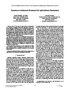
Use Case diagram for the Invoice System . . . . . . . . . . . . . . . .
55
17
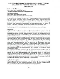
SSD for Place Order . . . . . . . . . . . . . . . . . . . . . . . . . . .
56
18
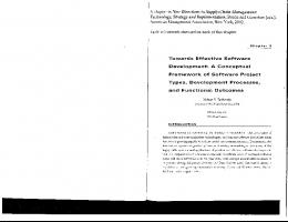
SDD for View Pending Orders . . . . . . . . . . . . . . . . . . . . . .
57
19
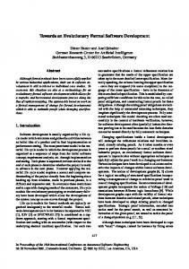
(Partial) Domain Model for Invoicing System
. . . . . . . . . . . . .
58
20
Composed Use Case Model . . . . . . . . . . . . . . . . . . . . . . . .
61
. . . . . . . . . . . . . . . . . . . . . . .
viii
21
Composed Domain Model . . . . . . . . . . . . . . . . . . . . . . . .
62
22
Communication diagram for orderProduct() with crosscuttings . . . .
64
23
Communication diagram for viewOrders() with crosscuttings . . . . .
65
24
Extended AOSD model . . . . . . . . . . . . . . . . . . . . . . . . . .
69
25
Invoicing System Domain Model: revisited . . . . . . . . . . . . . . .
85
26
Requirements Scattering Over Classes . . . . . . . . . . . . . . . . . .
88
27
Lack of Cohesion in Component . . . . . . . . . . . . . . . . . . . . .
89
ix
List of Tables
x
Chapter 1 Introduction 1.1
Introduction
The complexity of a software system is determined partly by its functionality and partly by the quality constraints on its development. According to the software engineering standard IEEE Std.830-1998 [83098], Functional Requirements (FRs) should define the fundamental actions that must take place in the software in accepting and processing the inputs and in processing and generating the outputs. These are generally listed as shall statements starting with “The system shall. . . ”. On the other hand, Non-Functional Requirements (NFRs) presents a systematic and pragmatic approach to building quality into software systems. According to IEEE Std.830-1998, NFR is defined as a software requirement that describes not what the software will do, but how the software will do it, for example, software performance requirements, software external interface requirements, software design constraints, and software quality attributes. During requirements engineering, NFRs tend to be stated in terms of the qualities or the constraints on the tasks which are FRs as the former affect the semantics of the latter.
1
An iterative software development process such as the one defined by the Unified Software Development Process (UP) [JBR99] is organized into a series of short fixed-length mini-projects called iterations, where each iteration represents a complete development cycle and is composed of a number of phases: requirements, analysis, design, implementation and testing. In the Rational Unified Process (R)UP, NFRs are listed in the Supplementary Specifications Document which starts during the Inception phase and normally gets refined in the subsequent phases over a number of iterations throughout development. However, the UP does not provide a special vocabulary or notation to support requirements specifications. Similarly the IEEE Standard 830-1998 describes a list of NFRs to be included in a Software Requirements Document. The FURPS+ model [GB92] used by the (R)UP refers to the following categories of requirements: Functional, Usability, Reliability (replaced by Dependability), Performance, Supportability and others. NFRs that fall into the URPS categories (FURPS excluding functional requirements) are called quality requirements. NFRs outside URPS are called constraints or pseudo-requirements. Once a software system has been deployed, it is normally straightforward to observe whether or not a certain FR has been met, as the areas of success or failure in their context can be rigidly defined. However, the same is not true for NFRs as these can refer to quantities that can be interdependent and difficult to measure. A decomposition approach proposed by [CNYM00] encompasses the refinement of NFRs into more detailed NFRs. Software quality models are used to determine to what extent software components satisfy the requirements of a given context of use [HF97]. A quality model is defined by means of general characteristics of software, which is further decomposed into sub-characteristics in a multilevel hierarchy; at the bottom of the hierarchy appear measurable software attributes. Furthermore, an interdependency may pose a tradeoff between NFRs. For example, as reliability increases, performance or cost are affected. In cases where conflicts between NFRs tend to arise,
2
developers must work out a satisfactory level of balance (tradeoffs) between them. Usually, NFRs are difficult to address in many applications, and are among the most expensive requirements to deal with. This is particularly true since NFRs are subjective in their nature and they have a broad impact on the system as a whole. Most approaches including the ones we discussed above, handle NFRs separately from FRs of a system. This shows evidence that the integration is difficult to achieve and usually accomplished at the later phases of the software development process. In addition, these approaches fail in addressing the presentation of how these NFRs can affect several FRs simultaneously. Since this is not supported from the requirements phase to the implementation phase, some of the software engineering principles such as abstraction, localization, modularization, uniformity and reusability, can be compromised. Furthermore, the resulting system is more difficult to maintain and evolve. This discussion highlights the needs to think of a new approach that would be capable of capturing and representing both FRs and NFRs from the requirement phase and map them properly to next phases of the software development. In this thesis, we propose a sequence of systematic steps under the umbrella of the Aspect-Oriented Software Development (AOSD); would be introduced in the next chapter, towards an early consideration of specifying and integrating FRs and NFRs. Our approach makes it possible to identify and manage conflicts between NFRs earlier in the development cycle and promotes traceability of broadly scoped requirements throughout system development, maintenance and evolution. In addition, we propose sets of quality measurements to be associated with the AOSD activities in order to assist stakeholders with quantitative evidences to better map or iterate system modules during the development process and to better set the design decisions for the analyzed requirements.
3
1.2
Major Contributions
This thesis offers the following contributions: • It proposes a new approach to identify, separate, and compose requirements starting from early requirements elicitation to implementation phase. • It provides clearly defined sets of measurements at three breakpoints during the development process: Analysis, Composing Requirements and Design. • It provides a new traceability mechanism through the software development process that enables stakeholders from tracing requirements with static and dynamic visions towards the developed software. • It provides a new mechanism to compose requirements that assist in integrating the captured main requirements with the crosscutting requirements. Our work in AOSD and measurements has been published in [KCO05], [OKC05] and [KOC05].
1.3
Thesis Outline
This thesis is organized as follows: • Chapter 2 provides the background. • Chapter 3 discusses the related work, highlights the open problems and provides the motivation. • Chapter 4 presents our solution illustrated on a case study. • Chapter 5 extends our solution with sets of measurements. • Chapter 6 outlines the conclusions and the research directions. 4
Chapter 2 Background “Let me try to explain to you, what to my taste is characteristic for all intelligent thinking. It is, that one is willing to study in depth an aspect of one’s subject matter in isolation for the sake of its own consistency, all the time knowing that one is occupying oneself only with one of the aspects. We know that a program must be correct and we can study it from that viewpoint only; we also know that is should be efficient and we can study its efficiency on another day [. . . ] But nothing is gained – on the contrary – by tackling these various aspects simultaneously. It is what I sometimes have called the separation of concerns”, Edsger W. Dijkstra [Dij76]. A software system is the realization of a set of concerns which are the primary motivation for organizing and decomposing software into manageable and comprehensible parts. Concerns come from a variety of sources, for example clients, developers, managers, administrators, firmware or hardware portions of a system and business context. Different viewpoints can have the same concerns, but the associated requirements may differ. For example, in a banking application the teller and loan officer may be concerned about access control. For a teller, the requirement maybe “teller 5
should not access loan information”. For loan officer the requirement maybe “loan officer should not manipulate loan amount”. Even though both view points have access control concern, the requirements are different. When Object-Oriented Programming (OOP) entered the mainstream of software development, it had a great impact on how software was developed as developers tackle larger systems with less time by modeling their concerns as groups of interacting objects and classes, which are generally derived from the entities in the requirements specification and use-cases. However, OOP is essentially static as a change in requirements can have an implication on development timelines. As discussed in the previous chapter, some requirements like NFRs need to be addressed in multiple modules of the system or they may need to be addressed in the system as a whole. Consequently, the code to handle these requirements may be mixed in with the core logic of a huge number of modules, resulting in bad implications on the software quality. Aspect-Oriented Programming (AOP) is a new promising programming paradigm that allows programmers to separate concerns and thus allows them to dynamically modify the static behavior of the object-oriented model. Just as objects in the real world can change their states during their lifecycles, an application can adopt new characteristics as it develops. This chapter aims to provide the background of the basic concepts associated with the AOP paradigm.
2.1
Crosscutting and separation of concerns
Despite the success of object-orientation in the effort to achieve separation of concerns, current OOP techniques support one dimensional decomposition of the problem focusing on the notion of a class. Such decomposition is not a good candidate to handle
6
Figure 1: Initial picture of crosscuttings
the complex interaction of components as it leaves certain properties without being localized in single modular units and as a result their implementation cuts across the decomposition of the system. This is the phenomenon of crosscutting. An initial picture of crosscutting is shown in Figure 1. The limitation in the modularization techniques that imposes only one way at a time on how the program could be modularized is called the tyranny of the dominant decomposition [TOHSMS99]. Multi-dimensional separation of concerns is aimed at breaking the tyranny to reduce software complexity and improve comprehensibility; promote traceability; facilitate reuse, non-invasive adaptation, customization, and evolution; and simplify component integration. With separation of concerns we would like to move from the picture in Figure 1 to one in Figure 2.
7
Figure 2: Initial picture of separation of concerns
8
As an illustrative example for the crosscutting, the code below is used based on the Observer design pattern. Class Point1 implements a geometrical point with x and y coordinates as instance variables and get/set methods. Class Subject is the part of the Observer pattern that maintains the list of observers for each subject, using the vector observers. This class is responsible for the notification of the observers by the method Notify(). class Point1 extends Object{ private int_x, _y;
void setX(int xx} {_x = x;} int getX() {return _x;}
void setY (int y) {_y = y;} int
getY () {return _y;}
... }
class Subject{ private Vector observers;
public Subject() {/* ... */}
public void attach (Observer o) { observers.add(o);}
public void Notify() { /* foreach observer.update() */} 9
... } class Point2 extends Subject {
(1)
public void setX(int x) { _x=x; Notify(); }
(2)
public void setY(int y) {_y=y; Notify();}
(3)
... } Class Point2 displays a possible enhancement of class Point1, named Point2, to incorporate the subject role using inheritance. This class has the following responsibilities: 1. After the execution of each method that changes the state of the object, the notification of the registered observers must take place. This is shown by lines (2) and (3). 2. This class inherits from class Subject to make the method Notify accessible for class Point1. As the source shows, the adaptation of the subject role results in crosscutting code (lines 2 and 3). To avoid this problem, other modularization and composition techniques should be used. Crosscutting is not a property of the implementation only but it propagates up to
10
Figure 3: Symptoms of crosscuttings
early stages of the software development. The conflict that tends to arise in ObjectOriented Software Development (OOSD), when we map requirements from its Ndimensional space to the single dimensional solution space constitutes the original source of crosscuttings (see Figure 3). Crosscutting imposes two symptoms on software development: 1. Code scattering: implementation of some concerns not well modularized but cuts across the decomposition hierarchy of the system. 2. Code tangling: a module may contain implementation elements (code) for various concerns. As a result of crosscutting, the benefits of OOP cannot be fully utilized, and 11
developers are faced with a number of implications: 1. Poor tractability of requirements: Mapping from n-dimensional space to a single dimensional implementation space. 2. Lower Productivity: Simultaneous implementation of multiple concerns in one module breaks the focus of developers. 3. Strong coupling between modular units in classes that are difficult to understand and change. 4. Low degree of code reusability. Core functionality impossible to be reused without related semantics, already embedded in component. 5. Low level of system adaptability. 6. Changes in the semantics of one crosscutting concern are difficult to trace among various modules that it spans over. 7. Programs are more error prone. 8. Difficult evolution.
2.2
Aspect-Oriented Programming
Aspect-Oriented Programming is a collective term that refers to a growing family of approaches and technologies that provide better linguistic mechanism for separation of concerns by supplying the process of software development with a second axis of decomposition that enables the identification and separation of core functionality and crosscutting requirements. Implementation of an AOP language seeks to encapsulate crosscutting concerns through the introduction of a new construct called an aspect. So, we can define an aspect as a modular unit of crosscutting implementation that encapsulates behaviors that affect multiple classes into reusable modules. 12
2.2.1
AOP History
It is hard to choose where to begin a history of AOP as many researchers were working on improving modularity for decades [FECA04]. The first main approach to improve software modularization under the “Aspect” umbrella is the one popularized by Xerox PARC team in 1997, led by Gregor Kiczales who is currently at the University of British Columbia, where he works on software modularity research. The team had invented AspectJ which is the most popular AOP language nowadays. The Xerox group’s work was integrated into the Eclipse Foundation’s Eclipse Java IDE in December 2002. This helped AspectJ become one of the most widely-used aspectoriented languages. The team of Xeroc PARC had worked previously on metaobject and reflection with ideas evolving to the modularization of ”crosscutting” concerns. Meanwhile, in 1993, a work titles “Subject-Oriented Programming” was published by a team from IBM T.J. Watson Research Center, led by William Harrison and Harold Ossher. Subject-oriented programming is an extension of OOP that supports building systems with different subjective perspectives on the objects of the system. For an example, an employee in the domain (perspective) of a payroll application may be quite different from an employee in the domain of a contact information system. Subject-oriented programming is a program composition technology that creates object-oriented system integrating these subjective perspectives. It can also add extensions to an existing system in a non invasive way. At the University of Twente in The Netherlands, Mehmet Aksit and his team had been working on Composition Filters since the early 1990s. With this approach, behavior is modularized in “filters” that can be used to capture and enhance the execution of object behavior. Karl Lieberherr at Northeastern University in the US defined the Demeter Method and the adaptive programming in the mid 1990s that provides abstractions of the class structure and navigation to support better separation of this knowledge from 13
an operation’s behavior. Today, AOP technologies are rapidly expanding and successively applied to crosscuttings. In spite of that, AOP is still quite a new paradigm, as there are lots of places where AOP can bring improvement.
2.2.2
AOP mechanism
The steps to successful aspect-oriented programming comprise: 1. Aspectual decomposition: identify core functionality and crosscutting concerns (aspects). 2. Implement each concern (relatively) separately. 3. Provide rules of composition between components and aspects. 4. Composition: can be achieved by a number of ways; the most dominant way is a linguistic approach: (a) linguistic mechanisms (constructs) to explicitly capture aspects. (b) provide special compilers (weavers) to combine components and aspects based on the rules provided in step 3. The sequence of steps results in an easy-to-use solution woven from smaller solutions. Figure 4 illustrates the weaving process. In this process, the original code does not need to know about any functionality the aspect has added; it needs only to be recompiled without the aspect to regain the original functionality. In that way, AOP complements OOP, not replacing it, by facilitating another type of modularity that pulls together the widespread implementation of a crosscutting concern into a single unit: aspect. Composition rules that would be specified in step 3 define two things:
14
Figure 4: AOP weaving mechanism
15
Figure 5: Components, Aspects and JoinPoints
1. Points of communication between components and aspects (joinpoints). 2. The semantics of aspects to be performed on certain joinpoints. The relationship between components, aspects and joinpoints is illustrated in Figure 5. Aspect-oriented technology has many potential benefits. It improves performance because the operations are more succinct and it allows programmers to spend less time rewriting the same code. As a sequence of the modularity improvement, AOP facilitates providing less tangled and less scattered code. In addition, it prompts good maintenance and higher level of adaptability. AOP may also be a great addition to quality professionals’ toolboxes. Using an AOP language, we might be able to test application code automatically without disturbing the code. This would eliminate 16
a possible source of error. Overall, AOP enables better encapsulation of distinct procedures and promotes future interoperation.
2.2.3
AOP Existing Frameworks
The concept of AOP is not bound to a specific programming language, and even not to OOP paradigm. Proposals for AOP with functional, logical and procedural programming can be found in the literature. The following is a list of tools that support AOP with the different languages: Tools for Java 1. AspectJ 2. The AspectBench Compiler for AspectJ (abc) 3. dynaop 4. JBOSS 5. AspectWerkz 6. The Spring Framework 7. JMangler 8. MixJuice 9. PROSE 10. ArchJava 11. JAC 12. Hyper/J
17
Tools for C/C++ 1. AspectC++ 2. XWeaver project Tools for C♯ / VB.NET 1. AspectDNG 2. Aspect♯ Tools for PHPaspect 1. Aspect-Oriented PHP Tools for Common Lisp 1. AspectL Tools for Cocoa 1. AspectCocoa Tools for Python 1. LightWeight Python AOP 2. Logilab’s aspect module 3. Python /Transwap AOP Tutorial 4. PEAK 5. Pythius
18
Even though AOP has been implemented in different languages, the language that gains a great interest of the research community is the Java language. Currently, AspectJ is the most notable AOP technology. AspectJ was created at Xerox PARC as a seamless aspect-oriented extension to the Java programming language. AspectJ is a superset of Java, so each valid Java program is also a valid AspectJ program.
2.2.4
AOP example with AspectJ
In this subsection we will show how to use AspectJ to trace the code. The code below depicts the bounded buffer example. A class Buffer contains mutator and accessor methods: 1. Mutators : put(), get() 2. Accessors: isFull(), isEmpty() public class Buffer { private String[] BUFFER; int putPtr; //keep track of puts int getPtr; //keep track of gets int counter; int capacity; Buffer (int capacity){} public boolean isEmpty() {} public boolean isFull() {}
public void put (String s) { if (isFull()) System.out.println(Error: Buffer full); else{ 19
BUFFER[putPtr++] = s; counter++; } }
public String get(){ if (isEmpty()) return Error: Buffer empty; else{ counter--; return BUFFER[getPtr++]; } } }
Every time we call a mutator method we want to display a message before the call for tracing purposes. We have to take three steps to implement our solution in AspectJ: 1. Identify places in the code where we want to insert the tracing method. This is called defining join points in AspectJ. 2. Write the tracing code which is displaying a message in this example. 3. Compile the new code and integrate into the system. Define the join points A joinpoint is a well-defined point in the code at which our concerns crosscut the application. In this example, we need to define two join points to capture any calls 20
to put() or get() in Buffer class. The joinpoint captures an execution point after it evaluates a method’s arguments, but before it calls the method itself.
call(public void Buffer.put(String)). call(public String Buffer.get()).
In AspectJ, we group join points into pointcuts. We may use logical operators in the definition of pointcuts in order to combine join points: 1. (OR operator): True if either one (or both) join points are captured by the expression. 2. (AND operator): True only if both join points are captured by the expression. 3. ! (NOT operator): Specifies a pointcut not captured by the specified join point. We define a pointcut named “mutators” that combines both join points: pointcut mutators() : call(public void Buffer.put(String)) || call(public String Buffer.get()) ; Write the tracing code The code to implement the tracing is similar to any method in Java, but it is placed with a new type, called an aspect. The aspect is the mechanism we use to encapsulate code to a specific concern. The implementation for the the tracing is shown below: public aspect Tracer{ pointcut mutators(): call(public void Buffer.put(String)) || call(public String Buffer.get()); before():mutators(){ System.out.println("-----Mutator method called"); 21
} } The aspect structure is similar to a class in Java. The aspect is typically placed in its own file, just like Java class. Following the pointcuts, we have a section code that is similar to a method in regular Java code. This is called advice in AspectJ. An advice must be defined with respect to a pointcut, in this example we define an advice to mutators. There is three ways to associate an advice with a pointcut: 1. Before: runs just before the pointcut. 2. After: runs just after the pointcut(maybe after normal return, after throwing an exception or after returning either way from a joinpoint). 3. Around: runs instead of the pointcut, with the provision for the pointcut to resume normal execution through proceed(). In AspectJ, pointcuts and advice together define the composition (weaving) rules. Compile the code Now that we have written the code, we need to compile it and integrate it into the existing system. For our example, we have a simple test class “BufferDemo” with a main method as shown below:
public class BufferDemo{ public static void main(String[] args){
Buffer buffer = new Buffer(10); buffer.put("Hello"); Buffer.put("there"); System.out.println(buffer.get());
System.println(buffer.get()); } 22
} In order to incorporate our aspect into the system, we add the aspect source code to the project and build with the AspectJ compiler, ajc. The compiler takes the aspect and creates class files that contain the advice code. Then, calls to the appropriate methods in these class files are woven into the original application code. With the current release of AspectJ, this weaving process takes place at the Java bytecode level. The output displayed out of executing BufferDemo with integration of aspect Tracer is shown below:
-----Mutator method called. -----Mutator method called. -----Mutator method called. Hello -----Mutator method called. there
2.3
Aspect-Oriented Software Development
While AOP supports separation of concerns at the code level, AOSD has extended AOP to provide a systematic support for the identification , separation , representation (through proper modeling and documentation ), and composition of crosscutting concerns as well as mechanism that make them traceable throughout software development. Although, initially the focus was merely on aspects at the programming level, recently a considerable amount of research has been focusing to identify and model
23
aspects in the early phases of software development. In the next chapter, we will provide an overview for selected researches on AOSD.
24
Chapter 3 Related Work, Open Problems and Motivation Despite a common and stable notion of aspects in the implementation level, the notion of aspect in the early levels of the development, also called early aspects, is not consolidated yet. In this chapter we will present an overview of the different techniques around early aspects modeling. This chapter aims at defining the open research issues in current AOSD techniques and providing motivation to work on our solution.
3.1
Related work
Current aspect-oriented approaches either concentrate on serving as a general purpose architecture modeling language within a particular domain, or support the analysis of one specific NFR of a system (e.g., performance or security) in a way that is not necessarily applicable to other NFRs and with an ignorance to possible existence of crosscutting FRs. In addition, these approaches do not fully support a smooth transition among the requirements, analysis and the design phases. In [RSMA02] and [RMA03], the authors propose an approach for modularizing 25
and composing crosscutting concerns. The approach involves identifying requirements using stakeholder’ viewpoints, use-cases/scenarios, goals or problem frames. The approach basically uses a set of matrices consisting of viewpoints and concerns represented in XML. Even though the authors show that some NFRs can crosscut viewpoint specifications, it is not clear how NFRs arise. The identification of the dimension of a candidate aspect (its influence on certain aspects of the system) is not performed in a systematic way in the paper. Scenarios tend to be treated as single modules (or black boxes) that have to be composed with crosscutting concerns. However, simple composition rules between scenarios and crosscutting requirements cannot be always applicable as relationships between them are normally not cleancut, this approach does not show the propagation of a scenario into a potentially large set of components inside analysis and design and the (normally complex) rules of composition between individual components and aspects. In fact, the influence of a single aspect policy on different sets of components that collectively implement the same scenario may be different. Similarly, the same aspect may influence the same set of components in a number of different ways. In this approach , resolving conflicts among concerns is recommended through negotiation with stakeholders, which may not always be applicable as; with the exception of developers, stakeholders are not interested in system concerns and they may not have the necessary expertise to be involved in these matters. They would merely want their requirements implemented. In [BM04], the authors propose an approach to identify and compose crosscutting concerns. The approach consists of four defined steps: identify concerns , specify concerns , identify crosscutting concerns and compose concerns. The composition of concerns is defined using the formal method LOTOS. The approach focuses on the requirements analysis phase, and contains no traceability support to other phases of the software development life cycle. It is not clear how we can map the LOTOS specification to the design and the implementation components. Resolving conflicts
26
among concerns is recommended through negotiation with stakeholders, which may not always be applicable as we discussed earlier. The approach recommends to define a dominant concern among the crosscutting concerns at certain joinpoint. The notion of a dominant concern cannot always be applicable. In complex systems (such as concurrent systems) two or more (aspects) may affect the same joinpoints with changing priorities to the execution of the behavior of some component (e.g. method body), so assigning a hard-coded prioritization will not follow the correct semantics. In [MAB02] , [PK04] and [AMBR02] composition of concerns is accomplished by extending UML models to integrate the candidate aspects to the functional behavior. Although the composition process must be considered at the meta-level, these approaches only model certain NFRs in a way that is not necessarily applicable for other requirements. There is no single formal method available that is well suited for defining and analyzing numerous NFRs for a system. In [CDDD03], the authors provide an approach to support one NFR, namely performance, using the UML and the formal architectural description language Rapide. Although the authors describe how they plan to extend their approach to support two or more NFRs, it is an open issue how to consider crosscutting FRs within their solution. In [TBB04], the authors adopt model analysis to detect semantic conflicts between aspects. The authors introduce two levels of conflicts among aspects: 1. Direct conflict: two or more aspects sharing the same joinpoint or an aspect is having a joinpoint in another aspect. 2. Indirect conflict: the aspects don’t share a common joinpoint but one aspect can have an impact on the behavior of the second. This approach is dedicated to serve the detection of direct conflicts only. Resolving conflicts is recommended through a process of correction and refinement of the model, 27
which is not clearly investigated. In [BB99] and [MRG+ 04], the obliviousness property was adopted to model orthogonal aspects independently from each other and from the functional requirements. The deployment of formal methods in these approaches (e.g. GAMMA, LOTOS, Time Temporal Logic) to specify the functional behavior and the associated aspects helps to enable formal validation and facilitates a specification-driven design. On the other hand, the weaving process is not presented in a precise systematic way and it is limited to a specific type of requirements that could not necessary be applicable for others. In addition, it is not clear where and how the formalism is to be placed within the AOSD framework or how to integrate it with the traditional iterative development process. In [NAB04], the authors reason about the semantics of the composition mechanisms of the programming language through an approach that is based on a single meta-model: Composition Graphs meta-model. While these graphs may provide a sufficient homogeneous comprehension for the semantics among different programming languages that make them easier to compare and to be transformed, the process to construct such graphs without existing tools can be tedious. In addition, the graphs are generated from an existing implementation that we don’t usually have when we initially develop the application. There is little work discussed in the literature on measurement in AOSD or AOP. The first set of object-oriented measures have been introduced in [CK94a]; their AOP counterparts are reported in [SGF+ 03]. Both are applicable at a class level from the design phase. In [Aha02], [ZX04] and [ZX03] the authors introduce a set of measures for aspect-oriented code complexity based on program dependency analysis.
28
3.2
Open problems
Based on the previous overview, we summarize the open problems in the current AOSD approaches as follows: 1. No clear defined activity on how to achieve integration among orthogonal / non-orthogonal FRs and NFRs at certain defined joinpoint. 2. No traceability support: Most of the approaches have a strong focus on a dedicated phase of the software life cycle with no traceability among the phases. 3. No clear and systematic activity to identify and resolve direct and indirect conflicts among aspects. 4. Strong focus on aspect identification and less work investigating how to model aspects through the different phases of the development. 5. No clear description on how NFRs arise within AOSD model. 6. Current approaches fail in addressing the crosscutting nature of some NFRs (i.e. reliability , portability , etc.) 7. Strong focus on considering the crosscutting nature of NFRs without addressing the possibility of having crosscutting FRs.
3.3
Motivation
To fill the gap raised from the previous open problems, we need to develop a systematic and precisely defined Aspect-Oriented model that supports not only capturing the requirements but also analysis and design of multiple functional and non-functional properties. Our model aims at achieving the following: 1. Eliminate the gap generated out of the diverse nature of FRs and NFRs. 29
2. Establish a systematic way to identify and resolve conflicts among crosscuttings. 3. Establish a smooth transition from requirements phase to the analysis and design phases. 4. Assist stakeholders with a quantitative analysis of quality in the analysis, design and implementation models of the software under the development. In the next two chapters, we will introduce our proposal and illustrate it within a case study.
30
Chapter 4 An AOSD model for specifying and separating concerns from requirements to implementation An effective software development approach must harmonize the need to build the functional behavior of a system with the need to clearly model the associated NFRs. In this chapter, our goal is to develop a systematic and precisely defined aspectoriented model towards an early consideration of specifying and separating crosscutting FRs and NFRs. This approach would make it possible to identify and resolve conflicts between NFRs earlier in the development cycle and can promote traceability of broadly scoped requirements through system development, maintenance and evolution. Our approach is illustrated within a case study.
4.1
The AOSD Model
Our proposed aspect-oriented model is depicted in Figure 6. The iterative and incremental nature of development is implied even though it is not explicitly captured in
31
Figure 6: AOSD model
the diagram. In our discussion, use-case driven activities will be adopted to model the system. Use-case modeling is a technique for capturing the functional requirements of the system. A use-case describes the typical interactions between the users of a system and the system itself that yield a result of value to the user. We argue that use-cases tend to be more concrete in their representation of the system as they explicitly state series of interactions between actors and the system. Furthermore, their representations tend to be easy to map to the next phases in development. Use-cases are also widely used as part of the de facto standard UML [Lar04]. On other hand, our approach is also applicable with goal-oriented and viewpointoriented driven activities. The supporting templates must be refined though to match the accompanying nature of activities.
32
In the following list, we will define some terms that we will refer to in our description of the AOSD model: • Activity: A named process or task that occurs over time and has recognizable results. In our model, the activity is the constructive unit. Each activity is having a specific input and output. • Phase: We refer to phase as a group of one or more activities within the AOSD model. The phase is a mean to categorize activities based on the general target they tend to achieve. Our AOSD model is composed of five phases: requirements elicitation, analysis and crosscutting realization, composing requirements, design and implementation. • Proposal: We refer to proposal as a detailed presentation to the project developed in response to specified requirements and/or motivation. In our work, we may use the term “proposal” for our AOSD model. In this section we will describe the activities and phases that form part of the model.
4.1.1
Requirements Elicitation Phase
Requirements Elicitation phase is composed of four activities: identifying FRs, specifying FRs, identifying NFRs and specifying NFRS. Identifying FRs Functional requirements capture the intended usage of the system. This usage may be expressed as services, tasks or functions which the system is required to perform. The context diagram could be an excellent starting point for capturing the system’s boundaries, users and FRs. Identifying FRs is a process that involves discussions with
33
stakeholders, reviewing proposals, building prototypes and arranging requirements elicitation meetings. Specifying FRs In this activity, we further refine each usage of the system into a detailed functional behavior described as a use-case with textual description. Thus, at this stage, each FR is mapped to one or more use-cases. The outcome of this activity is the completion of a use-case description for each use-case (Table 1.). Table 1 is similar to the fully dressed format [Lar04].
34
Table 1. Template to specify use-cases Use Case No.
Unique to the use-case.
Name
The name of the use-case.
Priority
Importance of the use-case.
Actors
Primary and secondary actors.
Precondition
Textual description of the condition that must be satisfied before the usecase is executed.
Main Scenario
A single and complete sequence of steps describing an interaction between a user and a system.
Alternative Sce-
Extensions or alternate courses of main
nario
scenario.
Postcondition
Textual description of the condition that must be satisfied after the use case is executed.
Related Cases
Use Use-cases related to the current usecase.
Identifying NFRs Nonfunctional requirements that are relevant to the problem domain are captured in parallel to the identification of FRs. Even though the elicitation of NFRs can be accomplished by a number of existing techniques, it is recommended to adopt the NFR catalog mechanism [CNYM00] where each entry in the catalog is crosslisted against the decision of whether it is applicable for the system or not. We propose the adoption of a matrix (Table 2) that relates the identified NFRs to the FRs they affect. In the case where an NFR would affect the system as a whole
35
(e.g. portability), all entries in the corresponding column must be checked.
Table 2. Matrix to relate NFRs to FRs NFR2
FR1
NFR1 √
FR2
√
√
. . .
NFRn
... FRn Specifying NFRs Since NFRs often invite many different interpretations from different people, they need to be clarified as much as possible through refinements in discussions with the stakeholders. Consider the development of a simple electronic order processing system. The system should receive orders from the customers, issue invoices, ship the goods, accept payments and issue receipts. In addition to these FRs, the system should also meet NFRs - good performance, easily extensible, user-friendly, security and highly reusable. The stakeholders represent NFRs explicitly as softgoals to be satisfied, i.e., goals to be satisfied not in a clear-cut sense but within acceptable limits. The best approach to specify NFRs is by using Softgoal Interdependency Graphs (SIG) [CNYM00]. SIG is a hierarchy graph of softgoals (i.e. NFRs) that shows the interdependencies between them(see Figure 7). Nodes of SIG are NFRs, and are represented by clouds, and the lines represent decompositions. When all sub-requirements of a given NFR are needed to achieve that requirement , an AND relationship is defined with an arc connecting the lines; otherwise, an OR relationship is defined with two arcs linking the decomposition lines. By the end of this activity, we further refine table 2 to show the relation of NFRs defined at the low level of the SIG and use-cases. 36
Figure 7: Softgoal Interdependency Grpah [CNYM00]
37
Figure 8: Tracing the dynamic behavior: Requirements Elicitation level
Table 3. Matrix to relate NFRs to use-cases NFR2
Use-Case1
NFR1 √
Use-Case2
√
√
. . .
NFRn
... Use-Casen From Requirements Elicitation to Analysis By the end of this phase, we are supposed to have successfully managed capturing and specifying FRs and NFRs of the system. We will use a hierarchy structure to trace the dynamic behavior of the system through the development process. By the end of this phase, the hierarchy should look similar to what we propose in Figure 8. We consider a use-case to be a set of scenarios describing instances of the usage of the system. Each scenario shows the real world concepts (including the system)
38
and the events interchanged between them, ordered in a time sequence. We map the scenarios to sequence of events that we will define further in the next chapter. The arrows between high level NFRS and FRs are extracted from the dependencies described in Table 2; while the arrows between low level NFRs and use-cases are extracted from Table 3. The arrow signifies that FRs or use-cases are to be provided through the system with the constraints implied by the associated NFRs. Having a high level NFR (e.g. X) been associated with a certain FR (e.g. Y) implies that at least one of the low level NFRs under the hierarchy of X is to be associated with at least one of the use-cases under the hierarchy of Y. It is important to keep in mind that the purpose of this hierarchy is to trace the dynamic behavior of the system and not to model system’s requirements. Modeling is to be accomplished within the next activities of the AOSD.
4.1.2
Analysis and Crosscuttings Realization
Software requirements analysis is a critical phase of the software development process, as errors at this stage inevitably lead to later problems in the system design and implementation. In our AOSD model, the analysis phase is composed of two activities: OO Analysis and Crosscutting realization. 00 Analysis The objective of the OO analysis activity is to understand the textual descriptions (requirements) that have been inducted in previous activities and to abstract the software under development into an OO analysis model. Analysis modeling is the formal or semi-formal presentation of the specification, through which the knowledge and information included in the textual description of the requirements are transmitted to the elements of the OO analysis model. The appropriate elements for OO analysis modeling are: use-case model diagram, System Sequence Diagrams (SSDs), domain 39
model diagram, activity diagram and state charts. In this discussion, we choose to focus on the first three diagrams to present the static and dynamic visions of the system. A domain model represents the static view and it illustrates meaningful (to other modelers) conceptual classes in a problem domain; it is the most important artifact to create during the OO analysis [Lar04]. On other hand, at this activity, we model each sequence of events that are mapped from a successful scenarios through an SSD. An SSD treats a system as a black box, placing emphasis on events that cross the system boundary from actors to the system and vice-versa. The set of all required system operations within a SSD is determined by identifying the system events [CS04]. Crosscutting Realization To identify the crosscutting nature of certain use-cases we need to take into consideration the information contained in row Related Use Cases in Table 1. If a use-case is included in several use-cases, then it is crosscutting. In spite of that, it is quite important to recognize that a certain use-case may seem to be crosscutting when defined at a certain abstract level, and then it could turn to be not crosscutting if we break it down to a finer level. It is hard to precisely define the level on which we shall be standing when defining and specifying use-cases. This issue will be further discussed in the case study. On the other hand, the identified NFRs are classified as crosscuttings as they are considered as global properties of the system and they always crosscut at different spots of it. In this phase, crosscutting requirements are not modeled. They are only identified. These requirements will be modeled at the integration activity during composing requirements phase.
40
Figure 9: Tracing the dynamic behavior: Analysis level
From Analysis to Composing Requirements The hierarchy structure we proposed before is a good candidate to trace the requirements from a dynamic point of view; and it should be updated by the end of this phase as shown in Figure 9. An arrow between two use-cases explains that the usecase at the tail of the arrow relies on the use-case at the head of the arrow to be accomplished. In order to trace requirements from a static point of view, we need a second hierarchy structure similar to one proposed in Figure 10. The diagram is built by relating the concepts modeled in domain model to use-cases they belong to. The diagram also shows that one concept could be shared among different use-cases. To see the relationships among the concepts themselves, we must refer to the domain model diagram.
41
Figure 10: Tracing the static behavior: Analysis level
4.1.3
Composing Requirements
The goal of composing requirements phase is to integrate identified crosscuttings (both functional and nonfunctional) with the use-case model and the domain model. This is achieved in a series of four activities: (1) identifying the interaction points at which crosscutting requirements affect the system, (2) identifying possible conflicts among requirements at each interaction point, (3) resolving conflicts, and (4) integrating requirements. Identifying interaction points Based on requirements crosscuttings (defined in 4.1.2), we can identify interaction points in the system where crosscuttings will manifest themselves. We start by defining the set of requirements R = {UseCases}∪ {NF Rs} , and the set of crosscuttings C = { crosscutting requirements (CCRs)}⊆ R. We also define the function A which maps R to set of CCRs as A : R → ℘(c) , where ℘ is a Powerset. A is supposed to track those requirements that traverse several other requirements captured by this
42
level of the development cycle. Let r ∈ R, c ⊆ C. We define A as: A(r) = φ, if there are no crosscutting requirements at r, and A (r) = c otherwise. The set of Interaction Points I is defined as : I = R − {r|A(r) = φ} We can illustrate the mapping of each element in I to a list of CCRs (Table 4), which is provided by function A.
Table 4: Mapping Interaction Points to CCRs P1
P2
...
Pn
CCRs
CCRs
...
CCRs
Defining conflicts Hardly any requirements manifest in isolation, and normally the provision of one crosscutting requirement may affect the level of provision of another. We refer to this mutual dependency as non-orthogonality. We define a function B for mapping of pairs of CCRs to values “+”, “-” ,“ ” or “?”: B : C × C → { “+”,“-”,“ ” ,“?” }. The rules for assigning the signs to the pairs of CCRs are as follows: 1. The value “-” is assigned to a pair of CCRs originating from the set of NFRs that contribute negatively at the same Interaction Point. This means that one CCR in the pair is having a negative (damage) effect on the other. The assignment is based on the experts judgment of the developers. 2. The value “+” is assigned to a pair of CCRs originating from the set of NFRs that contribute positively if they meet at the same Interaction Point. This means that one CCR in the pair is having a positive (constructive) effect on the other. The assignment is based on the experts judgment of the developers.
43
3. The value “ ” is assigned to a pair of CCRs originating from the set of NFRs that do not interact. The assignment is based on the experts judgment of the developers. 4. The “?” value would indicate a lack of information on the contribution; this might be updated in later phase of the software development lifecycle, or a subsequent iteration. 5. We assign “ ” to all pairs of CCRs where at least one CCR originates from the set of Use-Cases. The rational is that NFRs are usually constraints on UseCases, they do depend on each other, but the nature of this dependency cannot be positive or negative. We use Table 5 as a matrix presentation of the function B.
Table 5. Requirements contribution matrix r1 r1
r2
. . .
rn
+
r2
-
... rn
+
Resolving conflicts For each interaction point Pi ∈ I we analyze the set c = A(Pi ), and study the contribution among its elements. We are essentially interested in those elements (requirements) that have a mutual negative interaction. We manage conflict resolution by assigning priorities of execution of the crosscuttings by mapping A(Pi ) to a sequence Cseq , where Pi ∈ I . An element in the sequence is either a crosscutting or a set of crosscuttings. The set notation within Cseq indicates that the elements within 44
“{ }” are free to execute in any order relative to this position in the sequence, as there is no negative contribution identified. The process of mapping is guided by the expert’s opinion. Integration In the integration activity, we compose and model all requirements based on the collected information from previous activities. We extend the standard UML usecase diagram with a new stereotype hhCCRii to abstract the crosscuttings integrated into the model, and use the hhincludeii relation stereotype to indicate which use-cases are crosscut by the crosscuttings (see Figure 11).
Figure 11: Integrated Use Case model
The knowledge required for creating the extended use case model is extracted from Table 4. In Figure 11 , use-case1 , use-case2 ∈ I and aspect1 ∈ (A(use-case1) ∩ A(use-case2)). The algorithm for extending the standard use case model is as follows:
For each use case Pi , 45
For all crosscutting belongs to A(Pi) { If crosscutting is not in the use case model, 1- add it with the stereotype >. 2- add > relationship from Pi to the crosscutting.} We extend domain model to include all NFRs that have been elicited earlier. In Figure 10, we showed how each use-case is mapped to set of concepts. In this activity, we realize that for each NFR (e.g. X) affects a use-case (e.g. Y), X affects at least one defined concept under the hierarchy of Y. We have to define which concepts to be affected by which NFRs without breaking this rule. From Composing Requirements to Design The hierarchy structure for the static trace is to be updated by the end of this phase to look similar to what we propose in Figure 12.
Figure 12: Tracing the static behavior: Composing Requirements level
46
4.1.4
Design
For each use case in the analysis model, we refine further the system operations specified in its SSD into communication diagrams showing the design level details on the interaction between the objects involved in one system operation. Operationalizations are added further to SIG. Operationalization is defined as a possible design solution to satisfy the requirement [CNYM00] and it is represented with thick dark cloud with an arrow with a positive sign (See Figure 13). In case the operationalization is chosen to be a method to be implemented then we have to define: 1. The communication diagrams at which the operatioanlization will be involved. 2. Points of communication between the operationalization and objects in each communication diagram. 3. Semantics of communication between the Operationalization and objects in each communication diagram (before, after or around). We refer to this semantics as composition operators. If two operationalizations are intended to interact at the same point with the same composition operator, then we have to assign priorities to avoid a direct conflict. Priorities could be assigned based on cseq defined earlier. If two operationalizations are defined for the same NFR are to contribute at the same communication point (message) with same composition operator, then a further discussion with stakeholders is required to re-assign priorities. On other hand, if two use-cases (e.g. X and Y) having a common related usecase (e.g. Z), then it is of high probability (but not necessary true) that a common messages exchanged within communication diagrams defined under the hierarchy of use-case Z exist as common messages exchanged within communication diagrams 47
Figure 13: Operationalization in SIG
defined under the hierarchy of use-cases X and Y. Those common messages will be recognized in communication diagrams as they present a form of crosscuttings. We propose to present operationalizations and common messages generated out of a common functional behavior within communication diagrams using special notation: . N
Class diagram is built next using the domain model, and the composed communication diagrams. The approach is further illustrated on the case study From Design to Implementation We choose to map the design components to (Aspect J) code. The hierarchy diagrams used to trace the static and dynamic vision of the system are further extended to look similar to what we propose in Figures 14, 15 respectively. If an NFR is affecting a use-case then one or more of the operatioanlizatins defined under the hierarchy of that NFR will be affecting the messages defined under the hierarchy of the use-case. We are ready to map the design to implementation using the following rules:
48
Figure 14: Tracing the dynamic behavior: Design level
1. For each class defined in the class diagram, it will be mapped to a class in the implementation. 2. For each operationalization that appears in a communication diagram, it will be mapped to an aspect. 3. For each common message within two or more collaboration diagrams recognized out of a common functional behavior, it will be mapped to an aspect. 4. For each rule in the design that defines at which point in a communication diagram an operationalization or a common message will be involved (point of communication), it will be mapped to a joinpoint. 5. For each rule in the design that defines the composition operator for an operationalization or a common message, it will be mapped to an advice.
49
Figure 15: Tracing the static behavior: Design level
4.2
Case study
This section will illustrate how to apply the proposal in the context of a real system. The case study is chosen to be a web-based invoicing system. The system is capable of receiving multiple orders or cancellation requests at the same time. Multiple tellers can access the system to process orders and change their status from “Pending” to “Invoiced” if there is a sufficient quantity available; otherwise, the requested order will wait in a queue until the required quantity becomes available and a teller process the request. We assume that no multiple products are allowed to be requested in one order. The system requires its users to have a certain level of privileges to access any of the above functionalities except when searching for a product. The privileges are granted automatically upon successful authentication.
50
4.2.1
Requirements Elicitation
Identifying functional requirements Based on the requirements provided above, we can identify two actors: 1. Customer: Interested in searching the catalog, placing and canceling requests. 2. Teller: Tracks requests from customers and processes orders. We also identify the following FRs: (1) Search, (2) Place Order, (3) Cancel Order, (4) View Orders , (5) Process Order and (6) Process Payment. Specifying functional requirements In this presentation, we will map each FR to a use-case with the same name. Tables 6 and 7 show how the template described in the model is used for the use-cases Place Order and View Pending Order. In the rest of this illustration , we will continue focusing on these two use-cases.
51
Table 6: Place Order specification Use Case No.
2
Name
Place Order.
Priority
Maximum.
Actors
Customer.
Precondition
Ensure that the Customer is authenticated.
Main Scenario
The user accesses the terminal in order to place an order for one product. The user specifies the product numbers to be purchased along with the required quantity. The customer specifies his payment information at this stage to be verified and accessed in the process payment use case.
Alternative Sce-
If the product number placed is wrong, then the proper
nario
error message will be displayed and the user will be asked to search for the products using the search engine provided.
Postcondition
Ensure that a new invoice is created and it is assigned to a unique invoice number
Related
Use
Process Payment.
Cases
52
Table 7: View Pending Orders specification Use Case No.
5
Name
View pending orders.
Priority
Maximum.
Actors
teller.
Precondition
Ensure that the teller is authenticated.
Main Scenario
The teller accesses the system and chooses to view all pending orders. A list of the pending orders will be displayed.
Alternative Sce-
None.
nario Postcondition
Ensure that all invoices displayed are in Pending status.
Related
None.
Use
Cases
4.2.2
Identifying NFRs
For each entry in the NFR catalog, we decide whether or not it is related to the invoice system. In this case study, we will present the contribution of the following NFRs: Scheduling (SCH), Synchronization (SYN), Performance (PER), Multi Access (MA) and Security (SEC). In Table 8, we relate these requirements to the main FRs (use-cases in our case).
53
Table 8: Relating NFRs to FRs SCH
SYN
PER √
MA √
SEC √
FR2
√
√
√
√
√
FR3
√
√
√
√
√
FR4
√
√
√
√
√
FR5
√
√
√
√
√
√
√
√
FR1
FR6 Specifying NFRs
As discussed earlier, we further decompose NFR softgoals to a finer level. For example, security requirement is broad and abstract, to effectively deal with security we need to break it down into smaller components, so that the effective solution can be found. Security can be decomposed into sub-softgoals for the: integrity, confidentiality(CON) and availability (AVA) (see Figure 7). Similarly, performance can be broken down into space performance and response time (RT). In this study, we will present the contribution of response time , confidentiality and availability (See Table 9).
Table 9: Relating NFRs to Use-Cases SCH
SYN
CON
AVA √
FR2
√
√
√
√
√
√
FR3
√
√
√
√
√
√
FR4
√
√
√
√
√
√
FR5
√
√
√
√
√
√
√
√
√
√
FR1
FR6
RT MA √ √
54
4.2.3
Analysis and Crosscutting Realization
OO Analysis The use-case model in Figure 16 illustrates the context of the system in terms of FRs and how they relate to the actors. Use-cases Place Order and Cancel Order have been refined to factorize the Process Payment as a common functionality.
Figure 16: Use Case diagram for the Invoice System
The corresponding SSDs for Place Order and View Pending Orders use-cases are shown in Figures 17 and 18. The corresponding (partial) domain model is illustrated in Figure 19.
55
Figure 17: SSD for Place Order
Crosscutting Realization We can identify crosscutting FRs by analyzing the Related Use Cases row in the above use-case definitions. For example, Process Payment is a crosscutting use-case as it is included in both Place Order and Cancel Order use cases. It is important to make it clear that a crosscutting use-case at this level is not necessarily going to be mapped to an aspect at later stages of the development process. On the other hand it could be mapped to more than one aspect. This would depend on the level of abstraction at which we choose to model the functionality. For instance, usecase Process Payment could be further broken down to a finer level: Verify Payment Information, Make Debit Payment, and Process Refund. At the refined level, only Verify Payment Information use-case is a crosscutting component while Make Debit Payment only affects Place Order and Process Refund only affects the Cancel Order use-case. All defined NFRs are crosscuttings as each of them affects many interaction points
56
Figure 18: SDD for View Pending Orders or the system as a whole as we will illustrate next.
4.2.4
Composing Requirements
In the following, we will illustrate the required series of activities in order to compose requirements. Identifying interaction points Based on the last activity, we identify the set of crosscutting requirements as: {Process Payment, Synchronization, Scheduling, Response Time, Availability, Multi Access, Confidentiality}. The interaction Points are illustrated in Table 10.
57
Figure 19: (Partial) Domain Model for Invoicing System Table 10: Interaction Points Search
Place Or- Process
Cancel Or- View
Process
der
Payment
der
Orders
Order
RT
UC6
RT
UC6
SCH
SCH
AVA
SCH
AVA
RT
SYN
SYN
MA
SYN
MA
AVA
RT
RT
RT
CON
MA
AVA
AVA
AVA
CON
MA
MA
CON
SCH
CON
CON
MA
SYN
58
Identifying conflicts For each crosscutting requirement, we must identify its contribution to other crosscutting requirements and fill the matrix that we defined before. Based on the NFR catalogue, we could recognize that Availability has a positive contribution with MultiAccess and a negative contribution with Response Time. Table 11 illustrates the contribution (positive, negative or none) between crosscutting requirements.
Table 11: Candidate aspects contributions UC6
SYN
SCH
RT AVA
MA
CON
UC6 SYN SCH RT AVA
-
MA
-
CON
+ -
-
Resolving conflicts We reduce the conflict by assigning priorities for the negatively contributed requirements at each Interaction Point. We present below the ordered list of crosscutting concerns clist for each Interaction Point. A set within the list indicates that the set elements are free to execute in any order as there is no negative contribution identified. A (Search) = [AVA, RT, MA] A (Place Order) = [CON, AVA, MA,{RT, SCH, SYN, UC6 }] A (Process Payment) = [CON, AVA, RT, MA] A (Cancel Order) = [CON, AVA, MA,{RT, SCH, SYN, UC6 }] A (View Orders) = [CON, AVA, MA, {RT, SCH, SYN }] 59
A (Process Order) = [CON, AVA, MA, {RT, SCH, SYN }] Integration During integration FRs and NFRs are combined to obtain the whole system. The UML is used at this high level of abstraction to model the composition. In the new composed use-case diagram, we use the hhincludeii stereotype for each NFR and have the set of initial crosscutting use-cases include the new ones. Figure 20 shows a partial use-case diagram that includes the following use cases: Place Order, Cancel Order, View Orders and Process Payment while interacting with Response Time, Scheduling and Synchronization. Figure 21 shows the composed domain model with NFRs : CON, MA, AVA, SCH, SYN. Because CON is affecting Place Order use-case , then it must affect at least one concept under the hierarchy of Place Order as we discussed before. After analyzing the defined concepts, we found out that CON must be associated with the PlaceOrderSession. CON is affecting ViewOrdersSession in a similar way. AVA and MA are properties that affect the system as a whole and thus they are associated with the OrderingSystem concept. Because the system allows multi-access, we recognize readers-writers concurrency protocol to synchronize and schedule the write functionality(Place Order) and the read functionality (View Pending Orders). Scheduling and Synchronization are associated with the common “resource” that is accessed by both functionalities: OrderCatalogue.
4.2.5
Design
We will deploy operation contracts for orderProduct() and viewOrders() system operations specified within the Place Order and View Pending Order use-cases respectively. 60
Figure 20: Composed Use Case Model We further consider the appropriate operationalizations to be added in order to satisfy the specified NFRs. Only those Operationalizations that are chosen to be methods to be implemented will be integrated with the operation contracts and communication diagrams. In the invoicing system , CON will be possible through the operationalization “Authorize”. Both SCH and SYN are satisfied through operationalizations “Schedule” and “Synchronize”. For both operations: orderProduct() and viewOrders(), the system initially authenticates the corresponding actor to be eligible to use the service (addressed by 61
Figure 21: Composed Domain Model the synchronization aspect) before establishing what should be considered as the race condition between multiple actors due to the multi-access nature of the system (addressed by the scheduling aspect). Tables 12 and 13 show the operation contracts for orderProduct() and viewOrders() followed by the corresponding communication diagrams which illustrate the crosscutting view of CON, SYN and SCH (Figures 22, and 23 respectively).
62
Table 12: Operation contract for orderProduct() Operation
orderProduct()
Cross-reference
UC2: Place order
Precondition
hCON, SY N, SCHi
Postcondition 1. An order instance ord has been created (instance creation). 2. ord is associated with the order queue(formation of association). 3. hSCH, SY Ni
Table 13: Opeartion contract for viewOrders() Operation
viewOrders
Cross-reference
UC5: view Pending Orders
Preconditions
hCON, SY Ni.
Post-conditions 1. hSCH, SY Ni . 2. Ensure
that
the
appropriate
records displayed for all pending invoices.
Class diagram will be similar to the composed domain model, with addition of attributes and functionalities that will be added after analyzing the corresponding communication diagrams. NFRs will be replaced with corresponding operationalizations if these operationlizations are chosen to be methods (Authorize , Schedule and 63
Figure 22: Communication diagram for orderProduct() with crosscuttings Synchronize in our case). Other NFRs that are mapped to other forms of design solutions will not appear in the class diagram. To illustrate the mapping from design to implementation, we consider “Authorize” operationalization and “PlaceOrderSession” , “ViewOrdersSession” classes. Following the rules that we have specified in 4.1.4, we manage to map “Authorize” from the design domain to the solution space as follows: 1. “Authorize” is an operationalization that will be mapped to an aspect. 2. “Authorize” is invoked on either: calling makeOrder() message that will be implemented in PlaceOrderSession class OR calling view() message that will be implemented in ViewOrdersSession class. This rule defines the pointcut. 3. “Authorize” is to be invoked “before” the calls of the methods as the user must be authenticated before he is eligible to place an order or view orders as specified the use-case description at Tables 6 and 7. Using the above data, “Authorize” aspect is to be implemented as follows :
64
Figure 23: Communication diagram for viewOrders() with crosscuttings public aspect Authorize{ pointcut toAuthorize(): call(public void PlaceOrderSession.makeOrder(*)) || call(public void ViewOrdersSession.view(*)) before():toAuthorize(){ // Authentication Code } }
4.2.6
Discussion
Tangling and scattering are symptoms that do not exclusively affect implementation, but they also propagate to early stages of the development process. Identifying and modeling crosscuttings earlier in the software development process has a great impact on improving the general quality of the system and reducing complexity by (1) prompting understandability and reusability, (2) enhancing the process of detecting and removing defects, and (3) reducing development time. 65
In this chapter, we discussed a sequence of systematic activities towards an early consideration of identifying, specifying and separating broadly scoped requirements that are traceable throughout system development process. We addressed both FRs and NFRs as candidate crosscutting requirements. To compose requirements, we provided a fine grained approach to define interaction points and relate them to the level of use-cases. Our approach makes it possible to early recognize and resolve conflicts within the activity of composing requirements. We also provided traceability from static and dynamic points of views throughout the development process and we managed having one-to-one mapping from the requirements domain to the implementation space. On the other hand, we are aware that some crosscutting requirements are not easily captured through the development process; and thus stakeholders are in need for a feedback on the existence of crosscutting requirements that yet to be captured. In the next chapter, we propose sets of measurements applied at different breakpoints of the development process to help realizing early crosscutting implications in the system and thus help indicating possible crosscutting requirements that are not captured yet.
66
Chapter 5 Providing Quality Measurements for AOSD Adopting aspect-oriented technologies for software development requires revisiting the entire software lifecycle in order to identify and represent occurrences of crosscutting during software requirements engineering and design, and to determine how these requirements are composed. The consequence of that is a more interleaving of the software engineering processes and better specifications that map the problem and the solution components. In the previous chapter, we proposed a systematic and precisely defined aspectoriented model that supports capturing of the requirements as well as analysis and design of FRs and NFRs. This chapter builds on the proposed AOSD model while focusing and treating exclusively the subject matter of measurements. The intended goal is to assist stakeholders with quantitative evidences on the quality of the modeling decisions throughout the development process, and of the final product.
67
5.1
Extended AOSD Model
Throughout the development process, stakeholders are in need to verify that they managed capturing and specifying all related crosscutting requirements properly. To achieve this target, we choose to extend our AOSD model by proposing sets of quality measurements at different breakpoints during development. These measurements will assist stakeholders to better map or iterate the requirements of the system by providing them with quantitative evidences as a feedback on the following : 1. The existence of crosscutting requirements yet to be captured. 2. Decisions to be taken when setting the design strategies for the analyzed requirements. The proposed sets of measurements are as follows: 1. Requirements analysis measurements: A set of measurements applied on the specified requirements to help realizing early crosscutting implications in the system. 2. Interaction Points measurements: A set of measurements inducted to optimize the activity of composing requirements and to help setting better design strategies. 3. Design measurements: A set of measurements inducted at the end of the design activity to obtain quantitative evidence on the degree at which the crosscutting requirements have been separated, and thus to determine whether a further iteration would be required to generate a better modularized version of the system. The extended model is illustrated in Figure 24. In the following sections, we will present and discuss these sets of measurements. 68
Figure 24: Extended AOSD model
5.2
Requirements Analysis Measurements
Analysis modeling is the formal presentation of the specification, through which the knowledge and information included in the textual description of the requirements are transmitted to the elements of the object-oriented analysis models. In the AOSD model, the analysis model consists of a use-case model, system sequence diagram (SSD) (dynamic view on the system under development) and a domain model (static view). We see the set of use-cases in the resulting use-case model as a set of abstractions of the usages in the domain model reflecting the properties of the domain object they are to represent. One way to determine the quality of the software usage partitioning into use-cases is to look at how the activities between use-cases are related to one another. This is the criterion of lack of cohesion in the use-case model. 69
Another important way to evaluate the partitioning of the analysis model is by how the real-world concepts are related and depend on each other in the domain model. That is the criterion of coupling. Cohesion of the use-case model and coupling in the domain model are both ways of measuring the quality of partitioning in the analysis model. Associating the analysis with these measurements leads to early feedback on the existence of the crosscuttings yet to be captured and thus an early possible treatment. In this section, we proceed by introducing the notions of coupling and cohesion, summarizing the related work on coupling and cohesion measurements in the OOSD and AOSD, and then describing our proposal for obtaining early feedback on the levels of coupling and cohesion in the analysis model.
5.2.1
Background and Related Work on Cohesion and Coupling
Cohesion. According to the IEEE Standard Terminology, “cohesion is the degree to which the tasks performed by a single module are functionally related”. A software module is said to exhibit a high degree of cohesion if the elements in that unit exhibit a high degree of semantic relatedness. The high cohesion software development pattern suggests keeping the highest level of cohesion possible in software modules. In other words, each element in the module shall be essential for that module to achieve its purpose. A comprehensive survey of cohesion measurement approaches and measures is provided in [LB97]. The classical OO measure of class cohesion, LCOM, has been introduced in [CK94b]; its AOP counterpart is reported in [SGF+ 03]. The LCOM measurement attempts to measure structural cohesion rather than semantic cohesion,
70
thus dealing with the physical connections between the elements of a design component identified with an internal coupling. An attempt to provide a more precise OO cohesion measure for classes is presented in [WAW+ 05]. The common characteristics of all surveyed OO cohesion measures is that they target the cohesiveness of a class in the OO design / code. Our goal is to develop a mechanism dealing with the semantic relationship between the elements of a component and a single, overall abstraction (i.e., single, well-defined purpose) applicable to the analysis model, thus differing considerably from the existing work. Coupling. By definition, coupling is a measure of the interdependence among components in a software system that describes the nature, and the extend of the connections between the elements in the system. The motivation behind the low coupling pattern is to increase the predicting and controlling the scope of changes to a system. Complexity can be reduced by designing systems with the weakest possible coupling between classes, thus improving modularity and promoting encapsulation. The goal of coupling control is to limit any form of coupling to two kinds: a) which is inherent in the problem domain; b) which limits the type and scope of changes to as small a portion of the design as possible. The control is achievable through a software measurement mechanism providing feedback on the quality characteristics being measured. The classical OO measures of coupling have been introduced in [CK94b]; their AOP counterparts are reported in [SGF+ 03]. Both are applicable to a class level. An example of system-level OO design measurement is the MOOD set of measures [HCN98], including the Coupling Factor (CF). Our goal is to obtain a feedback on the level of coupling in the analysis model, that is, the coupling inherent in the problem domain, during the requirements analysis activity. The following subsections introduce the OO analysis measures in the AOSD model.
71
The proposed cohesion measurement mechanism is new and it allows for identifying crosscutting functional requirements at a fine-grained level during the elicitation of the use-case models. The proposed coupling measurement is an adoption of the existing OO design measure Coupling Factor introduced in [HCN98].
5.2.2
Measurement of cohesion
In the analysis phase we target the cohesion of the behavior description in the use-case model. Each use-case contains a set of scenarios representing instances of a usage of the system. A scenario is a set of paths and conditions that are of interest for the analysis of the system’s performance. Each scenario defines the expected behaviour of the system for a high-level system operation. We see the set of scenarios in the specified use-case model as a set of abstractions of the system usages reflecting the properties of the system functionality they are to represent. A scenario related to one goal of usage might include subgoals, or steps required to achieve the goal that by themselves qualify for a system usage abstraction. For instance, the goal of “booking a trip” might include the subgoals of a booking of a flight and reservation of a hotel which are triggered by the corresponding requests for reservation and resulting in approval of the reservation, therefore being classified as usage abstractions themselves. Intuitively, this is an example of a low cohesion as two usage goals (booking a flight and booking a hotel) which semantically independent are related in one usage goal (booking a trip) by the sequence of actions in time. On the other hand, another use-case named “registering for a conference” might include the “booking a hotel” usage goal extended with options related to a specific category of customers. In this case, we say that the subgoal of “booking a hotel” is crosscutting both use cases “booking a trip” and “registering for a conference”. Our goals are to measure the cohesion of a use-case model. The cohesion measurement mechanism allows for identification of the crosscutting (sub)goals (or concerns) 72
in the use-case model. The crosscutting subgoals are lowering the level of cohesion in the use-case model, as described before, and their identification is crucial for the further phases of the AOSD. The proposed cohesion measurement mechanism is based on the notion of similarities among different scenarios as described below. Measurement Method We formally specify a scenario S as S = (SE,
6 SE ,
SO, MEO, MET), where SE rep-
resents all the environmental (Input/Output) events participating in the scenario, 6 SE
is an order imposed on the events in time, SO is the set of domain concepts
participating in the scenario, MEO is a mapping from SE to the pairs of objects that exchange events, and MET is a mapping from SE to the time axis. The environmental Input/Output events in a scenario are observable. The ordering 6
SE
always produces
a legal sequence of events, where legal means that the first event is an environmental Input event which is unconstrained, the last event is an environmental output event, and the partial order between the events satisfy the ordering
6 SE .
The term legal
sequence has been first introduced in [AOL04].
We state that a crosscutting concern is a subgoal corresponding to a legal subsequence common to at least two scenarios belonging to different use cases. Let two different use-cases UA and UB be defined by the sets of scenarios Σ1 and Σ2 respectively where each scenario is a legal sequence of events. We say that Σ1 and Σ2 operate on a common legal subsequence σ of events when σ is a subsequence of both a scenario S1 ∈ Σ1 and S2 ∈ Σ2.Intuitively, the existence of similar legal subsequences of events within scenarios of different use-cases indicates a low modularity, i.e., low level of partitioning quality. The Cohesion Level in the Use-Case Model measure is defined on the set of all scenarios belonging to all use-cases in the use-case model:
73
CL UCM = 1 −
|QM| |P M|
(1)
where QM is the set of the pairs of scenarios that operate on a common legal subsequence of events, each pair containing scenarios belonging to different use-cases, and PM is the set of all pairs of scenarios (same condition apply). The following steps are defined for our measurement method: • Step 1. Map each scenario in Σ to a timed sequence of events ℑ. • Step 2. Identify the set ℜ of legal subsequences for each sequence ℑ. • Step 3. At this step, the set QM is identified. For each pair of scenarios (order is not important to avoid duplication of the results) find the intersection of the corresponding sets of legal subsequences. If the intersection is nonempty, add the pair to the set QM. The non-empty intersections not only indicate the presence of candidate crosscutting concerns, but also identify them. • Step 4. Calculate |P M|. • Step 5. Calculate CL UCM. The unit of cohesion in the CL UCM measure is a crosscutting concern abstracted as a pair of scenarios whose goals are related by the given crosscutting concern. The scale type of CL UCM is absolute since the only allowable transformations are identities, and there exist an absolute zero indicating a lack of the quality attribute (cohesion) in the use-case model. The range of the values for the measure CL UCM is [0..1], where 1 indicates the highest level of cohesion (there is no intersection between the scenarios from different use-cases), and 0 indicates the lack of cohesion (all pairs of scenarios are crosscut). Higher CL UCM values indicate that possible crosscuttings are to be identified.
74
Formal Properties of Cohesion The CL UCM measurement is theoretically validated against the set of axioms proposed in [Whi97]: 1. Cohesion is non-negative. Yes. Discussion: the ranges of values is [0..1], therefore negative values are not allowed. 2. Cohesion is independent of size Yes. Discussion: CL UCM targets the usage model of the system without accounting for the size aspects. 3. Cohesion can be null Yes. Discussion: the 0 value for the cohesion indicates lack of it in the use-case model. 4. Cohesion of a collection of elements or properties is independent of the internal structure of the collection of its components. Yes. Discussion: CL UCM targets the usage of the system without taking into account the domain model representing its structure. 5. Cohesion forms a weak order. Yes. Discussion: we can always compare and order the use cases model in terms of their CL UCM values.
5.2.3
Measurement of coupling
In the analysis activity, we target the coupling in the domain model. We have adopted the MOOD Object-Oriented Software measurements [HCN98] Coupling Factor measure to quantify the existing level of coupling in the domain model due to associations between the conceptual classes. 75
Coupling Factor (CF) is a measurement of the level of coupling in the (partial) domain model and is defined as follows:
CF =
PT C PT C i=1 [
j=1 is T C2
client(Ci , Cj )] − TC
where TC is the toal number of concepts (classes) and is client(Cc , Cs ) =
1, if f Cc ⇒ Cs ∧ Cc 6= Cs ;
(2) 0, oherwise. and Cc ⇒ Cs represents the relationship between a client class Cc and a supplier
class Cs . The range of the values for the CF is [0..1], where 0 indicates lack of coupling, and 1 is corresponding to the highest possible level of coupling. As a higher value of CF would indicate higher level of coupling between the concepts in the (partial) domain, this value may be considered as an implication of crosscutting requirement(s) to be realized. The unit of measurement in our version of the CF measure is an abstraction of the coupling unit, namely, an association between two concepts in the domain model expressed as an ordered pair of concepts (Ci , Cj ). The scale type of the CF measure is absolute since the only allowable transformations are identities, and there exist a hypothetical absolute zero indicating a lack of the quality attribute (coupling) in the domain model. We have validated theoretically the proposed coupling measure against the axioms for coupling proposed in [Whi97], as discussed below. Formal Properties of Coupling 1. Coupling is non-negative. Yes. Discussion: the range of CF values is [0..1], therefore negative values are not allowed. 2. Coupling can be null. 76
Yes. Discussion: theoretically, the domain model can exhibit 0 coupling corresponding to the lack of it in the model. 3. Adding an intercomponent relationship does not decrease coupling. Yes. Discussion: adding one more association would increase the value of CF. 4. Merging two components does not increase coupling. Yes. Discussion: the number of coupled pairs of concepts will remain the same or decrease (if duplicated), the number of classes might increase, therefore the CF value would eventually decrease. 5. Merging two unconnected components does not change coupling. No. Discussion: the number of coupled pairs of concepts will remain the same, the number of classes might increase, therefore the CF value would in general change. 6. Coupling forms a weak order. Yes. Discussion: domain models can be ordered in terms of their coupling.
5.3
Interaction Points measurements
As described in chapter 4, Interaction Points are the identified requirements in the system where other requirements may crosscut. In this section we propose set of measurements to obtain a quantitative analysis of the characteristics of Interaction Points such as size, cohesiveness, local conflict, interdependency, independency and complexity. These measurements intend to assist the effort required for the composition of the requirements, and to provide a solid ground for making decisions and setting priorities while mapping candidate elements through the next activities of the development process. In these measurements, we will refer to functions A and B that we have defined in the chapter 4. 77
5.3.1
Relative Size
The relative size of the Interaction Point is a measurement for how many crosscuttings affect a given Interaction Point Pi ∈ I in relative to other Interaction Points defined in the system (set I): |A(Pi )| RelativeSize(Pi ) = Pn k=1 |A(Pk )|
(3)
where n is the cardinality of the set I. The relative size is a non-negative value in the interval [0..1] interpreted as a relative weight of a given Interaction Point.
5.3.2
Local conflict
The effort required for the integration process would highly depend on the level of interdependency between the crosscutting requirements, and more specifically on the defined conflicts at Table 5. We propose to use the local conflict measure which reports the level of conflict LLC (Local Level of Conflict) for each Interaction Point Pi ∈ I based on the list of crosscutting requirements (Pi ). LLC(Pi ) = |{(CCRk , CCRl )·CCRk , CCRl ∈ A(Pi )∧B(CCRk , CCRl ) = ”−”}|/n (4) where n is the cardinality of the set of all pairs of CCRs in A(Pi ) (the order is ignored to avoid duplications).
5.3.3
Interdependency
Similar to LLC, we propose to track the level of interdependency LLI (Local Level of Interdependency) for each Interaction Point Pi ∈ I based on the list of cross cutting requirements A(Pi ): 78
LLI(Pi ) = |{(CCRk , CCRl )·CCRk , CCRl ∈ A(Pi )∧B(CCRk , CCRl) = ”+”}|/n (5) where n is the cardinality of the set of all pairs of CCRs in A(Pi ) (the order is ignored to avoid duplications).
5.3.4
Independency
We use this term to indicate to which level crosscutting requirements are independent from each other at a certain Interaction Point. So for each Interaction Point Pi ∈ I based on the list of crosscutting requirements A(Pi ), we define Local Level of Independency:
LLI(Pi ) = |{(CCRk , CCRl )·CCRk , CCRl ∈ A(Pi )∧B(CCRk , CCRl) = ”
”}|/n (6)
where n is the cardinality of the set of all pairs of CCRs in A(Pi ) (the order is ignored to avoid duplications).
5.3.5
Complexity Profile of the Interaction Points
At this level of abstraction, we propose that source of complexity at an arbitrary Interaction Point rises up from negative contribution among requirements. We relate complexity of an arbitrary Interaction Point to other Interaction Points complexities in the system using the following formula:
79
Complexity (Pi ) = |{(CCRk ,CCRl )·CCRk , CCRl ∈ A(Pi ) ∧B(CCRk , CCRl ) = ” − ”}|/
Pn
j=1 |{(CCRk , CCRl )
· CCRq , CCRr ∈ A(Pj ) ∧ B(CCRq , CCRr ) =
” − ”}|(7) The figures obtained at this level from the above proposed measurements are supposed to direct the effort towards a better design strategies and decisions. For example, an Interaction Point with a high complexity or a relative size value requires more effort to configure and design; consequently, a more brains, time, and money are to be dedicated.
5.4
Design Measurements
Within object-oriented software development, the design phase takes place when the functionality of the set of entities defined in the domain model is modeled as a set of interacting software classes with a clearly defined properties and behavior. In AOSD, the design phase extends this transformation to map candidate aspects defined in earlier stages to a 1) design decision, 2) defined function or 3) a real aspect. In this section, we define set of measurements for separation of requirements, cohesion and coupling for the system. These measurements are applicable to both phases: design and implementation. We use a template (See Table 14) to clarify the relations.
5.4.1
Separation of requirements
Separation of requirements measurement quantifies the degree to which a single requirement in the system maps to the design components (classes and aspects) and to the operations defined within the methods and the advices. We define the separation of requirements in terms of:
80
• Requirement scattering over classes and aspects (RSCA): counts the number of classes and aspects from Table 14 whose main purpose is to contribute to the implementation of the requirement. • Requirements scattering over methods and advices (RSMA): counts the number of class methods and aspect advices and methods from Table 14 whose main purpose is to contribute to the implementation of the requirement. High RSCA and/or RSMA values for a specific requirement signals low modularity and thus a high probability of an existence of crosscuttings to be captured.
81
Table 14: Requirements tracing among classes, aspects and operations r1
r2 ..
rn
classes class1
√
m1 √
m2 ··· m( Numberof methodsinclass1) class2
√
m1 m2 ··· m( Numberof methodsinclass2)
···
···
classi
m1 m2
···
···
Aspects Aspect1
advice1 advice2 ··· advice( Numberof advicesinaspect1) m1 m2
···
··· m( Numberof themethodsintheaspect
..
..
..
82
..
..
..
5.4.2
Lack of cohesion
We use an inverse measure of cohesion, lack of cohesion, to measure how much the responsibilities are tangled within a certain component (class/aspect) or operation (method / advice). • Lack of cohesion in component (LOCC): counts the number of requirements from table 14 that are implemented within certain class or aspect. • Lack of cohesion in operation (LOCO): counts the number of requirements from table 14 that are implemented within certain operation. Higher LOCC and/or LOCO values indicate low of cohesion for a certain component or operation due to the low level of modularity. A further iteration is required to achieve a better separation of requirements.
5.4.3
Coupling
We propose to apply the same coupling measurement we used in the analysis level on both classes and aspects separately. According to this, we define CFclasses , CFaspects . As in the analysis phase, high values for CF could be an implication of a bad design separating the contributed requirements.
5.5
Case Study
This section will illustrate how we have applied our proposed measurements in the context of real system. We will use the same invoicing system case study we used in the previous chapter. We have developed an application to assist the effort of generating the design measures automatically. We will illustrate the results of the application in this section as well. 83
5.5.1
Requirements Analysis Measurements
The requirements analysis measurements are illustrated in the context of Place Order and View Pending Orders usages. We are concerned with the main (successful) scenarios. The main scenarios for these use-cases are represented graphically through SSDs in Figures 17 and 18. If we apply our measurement mechanism described to the Place Order and View Pending Orders use-cases, we obtain that set PM is equivalent to QM due to the hAuthentication(), Message()i legal sequence. A common sequence results in reducing the cohesion level in the use-case model as it increases QM values and thus reduces CL UCM value. Therefore, the above two use-cases are considered as candidates for crosscutting FRs in our AOSD model. In such a case, it is recommended to restructure the use-case model to have “login” as a separate use-case. To be able to calculate the CF value for the domain model 19, we need to identify the “is client” relation among the concepts. We update the domain model in Figure 19 to specify the navigation through the relations among the concepts (Figure 25). The total number of concepts (TC) is 10. Applying the CF measures in the context of this domain model , generates the value of 0.1 which is considered a good level of necessary coupling.
5.5.2
Interaction Points Measurements
Table 15 summarizes the set of measurements we proposed for the Interaction Points in the invoicing system. All figures in the table are intended to be followed with % sign.
84
Figure 25: Invoicing System Domain Model: revisited Table 15: Interaction Points measurements FR1
FR2
FR3
FR4
FR5
FR6
Relative Size
9.7
22.6
16.1
19.4
19.4
12.9
LLC
66.7
14.3
30
20
20
50
LLI
33.3
3.6
6.7
4.8
4.8
10
LLInd
0
82.1
63.3
75.2
75.2
40
Complexity
11.8
17.6
17.6
17.6
17.6
17.6
Table 15 provides the designers with figures to assist in building design strategies based on stakeholders and environmental requirements. For example, it could be possible that designers are interested in starting with the most complex requirement to build or they would like to assign the reasonable resources to requirements based on complexity and relative size. In our case, Place Order, View Pending Orders and Cancel Order are the FRs with the highest 85
Relative Size and complexity values; thus more resources and time are to be dedicated for them. Choosing which of these measurements are to be taken into consideration is left for the expert’s judge upon the environmental constraints. For example, LLC value for “Search” use-case indicates a high value of conflict among CCRs; but at this Interaction Point we have only three CCRs so the value of LLC is not efficient by itself to build the strategy for assigning resources and thus it is important to consider the values of Relative Size and Complexity as well. LLI could be considered if the stakeholders would like to build their strategies based on the collaborative contribution rather than the damage contribution among CCRs.
5.5.3
Design Measurements
To assist the effort of applying the design measurements, we have developed an application with multi-tapped form. The output of the application is a specific report generated upon the user’s choice of applying one of the supported design measurements. The user has to specify the following inputs: • Use-Cases: A unique number will be assigned automatically for each usecase. • NFRs: A unique number will be assigned automatically for each NFR. • Classes: While entering the classes that appears in the class diagram, the user has to specify the “parent” classes that exist for each class to enable calculating the CF measurement. The user has to specify the methods for each class. A unique number will be assigned for each method. • Operationalizations: The user has to specify the operationalizations that appear in the composed class diagram. He/She further has to specify at
86
which class and which method each operationalization will affect and when (before, after or around). • Requirements-Components-Level: For each use-case and NFR, the user specifies which of the existing classes and/or aspects are involved in its implementation. • Requirements-Operation-Level: For each use-case and NFR, the user specifies which of the existing methods and/or advices are involved in its implementation. After specifying the above inputs, the user chooses which measures to apply on the data : RSCA , RSMA, LOCC, LOCO or CF. For the invoicing system case study, applying the requirements scattering among classes and aspects (RSCA), the application generates the diagarm at Figure 26 counting how many classes/aspects are involved in implementing each requirement. The diagram shows the measures applied for Place Order, View Pending Orders, Cancel an Order, Make Payment, Scheduling , and Synchronization. The diagram clearly shows that having SCH and SYN been separated as individual modules (aspects) is reducing the RSCA values for these NFRs to one for each. Otherwise, two classes will be involved in implementing each of them: (PlaceOrderSession) and (ViewOrdersSession). Applying the lack of cohesion in component (LOCC), the application generates the diagram at Figure 27 counting how many requirements will be (partially) implemented per each class or aspect. We show the results for the classes: viewOrderSession and OrderCatalogue and for the operationalizations (aspects): SCH , SYN and CON.
87
Figure 26: Requirements Scattering Over Classes
Choosing not to encapsulate SCH and SYN as a separate aspects will increase the number for the class OrderCatalouge by 2 as these NFRs will be implemented within the code of this class by then; thus reducing the cohesion level.
88
Figure 27: Lack of Cohesion in Component
89
Chapter 6 Conclusions The increasing trend to develop complex software systems has highlighted the need to consider software quality as an integral part of software system development. Separation of Concerns is fundamental software engineering that is aimed at breaking the tyranny of dominant decomposition. Despite the success of object-orientation in the effort to achieve separation of concerns, both functional and nonfunctional, certain properties in OO software system cannot be directly mapped from the problem domain to the solution space, and thus they cannot be localized in single modular units. These properties have been studied under the name of crosscutting concerns (or aspects). The symptoms imposed by the existence of crosscutting concerns manifest themselves as the scattering of concerns across the decomposition hierarchy of the system and the tangling of concerns within modular units. AOP is a term adopted to describe an increasing number of technologies and approaches that support the explicit capture of crosscutting concerns (or aspects) whereby the implementation of functional components and aspects is performed (relatively) separately, and their composition and coordination (referred to as weaving) is specified by a set of rules. Aspect-Oriented Software Development (AOSD) has extended AOP to 90
provide a systematic support for the identification, separation, representation (through proper modeling and documentation), and composition of crosscutting concerns as well as mechanisms that make them traceable throughout software development. In this thesis, we introduced a sequence of systematic activities towards an early consideration of specifying and separating crosscutting FRs and NFRs. We also introduced different sets of measurements based on the notion of crosscutting concerns to assist the identification and modeling of the early crosscutting implications in the system. Our work in AOSD and measurements has been published in [KCO05] where we proposed the AOSD model and in [OKC05] where we proposed the requirements analysis measurements and in [KOC05] where we proposed the rest of the measurements. There are several avenues of future work that we could effectively pursue. Our main interests are in: • Establishing a formal way to identify conflicts among aspects at certain join point. The main target will not be limited to direct conflicts only but will include the indirect conflicts as well. • Establishing a formal methodology to resolve the conflict with minimal contribution from stakeholders. • Establishing formal one-to-one mapping with the matching components at later stages of the development. • Applying our sets of measurements in a general context of AOSD. • considering an aspect as a crosscutting in another aspect.
91
Bibliography [83098]
IEEE Std. 830-1998. IEEE recommended practice for software requirements specifications. IEEE Transactions on Software Engineering, 1998.
[Aha02]
J. Ahao. Towards A Metrics Suite for Aspect-Oriented Software. Technical Report SE-136-25, Information Processing Society of Japan (IPSJ), 2002.
[AMBR02]
J. Araujo, A. Moreira, I. Brito, and A. Rashid. Aspect-Oriented Requirements With UML in Conjunction with 1st International Conference on Aspect-Oriented Software Development. In Workshop on Early Aspects in Conjunction with 3rd International Conference on Aspect-Oriented Software Development, Enshede, Netherlands, 2002.
[AOL04]
V.S Alagar, O. Ormandjieva, and Shi Hui Liu. Scenario-Based Performance Modelling and Validation in REal-Time Reactive Systems. In Processing of Software Measurement European Forum(SMEF2004), 2004.
[BB99]
L. Blair and G. Blair. A Tool Suite to Support Aspect-Oriented Specification.
In Aspect-Oriented Programming Workshop in
Conjunction with the 13th European Conference on ObjectOriented Programming, pages 7–10, Lisbon, Portugal, 1999. 92
[BM04]
I. Brito and A. Moreira. Integration the NFR Framework in a RE Model. In Workshop on Early Aspects in Conjunction with 3rd International Conference on Aspect-Oriented Software Development, Lancaster, UK, 2004.
[CDDD03]
Kendra Cooper, Lirong Dai, Yi Deng, and Jing Dong. Towards an Aspect-Oriented Architectural Framework. In 2nd International Workshopon Aspect-Oriented Requirements Engineering and Architecture Design (Early Aspects), Boston, MA, 2003.
[CK94a]
S. Chidamber and C. Kemerer. A Metrics Suite For ObjectOriented Design. IEEE Transactions on Software Engineering, 20(6):476–493, 1994.
[CK94b]
S. Chidamber and C. Kemerer. A Metrics Suite for ObjectOriented Design. IEEE Transactions on Software Engineering, 20(6):476–493, 1994.
[CNYM00]
L. Chung, B. A. Nixon, E. Yu, and J. Mylopoulos. Nonfunctional Requirements in Software Engineering. Kluwer Academic Publishing, 2000.
[CS04]
Constantinos Constantinides and Therapon Skotiniotis. The Provision of Contracts to Enforce System Semantics Throughout Software Development. In Proceedings of the 8th IASTED International Conference on Software Engineering and Applications (SEA2004), Cambridge, MA, 2004.
[Dij76]
E.W. Dijkstra. A Discipline of Programming. Prentice-Hall, Englewood Cliffs, NJ, 1976.
[FECA04]
Robert Filman, Tzilla Elrad, Siobhan Clarke, and Mehmet Aksit. Aspect-Oriented Software Development. Addison-Wesley, 2004. 93
[GB92]
Grady and Robert B. Practical Software Metrics for Project Management and Process Improvement. NJ:Prentice-Hall, 1992.
[HCN98]
R. Harrison, S. J. Counsell, and R.V. Nithi. An Evslustion of the MOOD Set of Object-Oriented Software Metrics. IEEE Transactions on Software Engineering, 24(6):491–496, 1998.
[HF97]
Tracy Hall and Norman E. Fenton. Implementing Effective Software Metrics Programs. IEEE Software, 14(2):55–65, 1997.
[JBR99]
I. Jacobson, G. Booch, , and J. Rumbaugh. The Unified Software Development Process. Addison-Wesley, 1999.
[KCO05]
Mohamad Kassab, Constantinos Constantinides, and Olga Ormandjieva. Specifying and Separating Concerns From Requirements to Design: a Case Study. In The IASTED International Conference on Software Engineering (ACIT-SE 2005), pages 18– 27, Novosibirsk, Russia, 2005.
[KOC05]
Mohamad Kassab, Olga Ormandjieva, and Constantinos Constantinides.
Providing Quality Measurements for Aspect-
Oriented Software Development.
In Accepted at First Asian
Workshop on Aspect-Oriented Software Development, Taipei, Taiwan, 2005. [Lar04]
C. Larman. Applying UML and Patterns; An Introduction to Object-Oriented Analysis and Design and the Unified Process, 3rd edition. Upper Saddle River, NJ: Prentice Hall Inc., 2004.
[LB97]
J. Wust L. Birand, J. Daly. A Unified Framework for Cohesion Measurement in Object-Oriented System. 4th International Software Metrics Symposium (METRICS’97), pages 43–53, 1997.
94
[MAB02]
A. Moreira, J. Araujo, and I. Brito. Crosscutting Quality Attributes for Requirements Engineering. In 14th International Conference on Software Engineering and Knowledge Engineering, pages 167–174, Ischia, Italy, 2002.
[MRG+ 04]
M. Mousavi, G. Rusello, M. Ghaudron, M. Reniers, T. Basten, A. Corsaro, S. Shukla, R. Gupta, and D. Schmidt. ASpects + GAMMA = AspectGAMMA: A Formal Framework for ASpectOriented Specification. In Workshop on Aspect-Oriented Modeling with UML in Conjunction with 1st International Conference on Aspect-Oriented Software Development, Enshede, Netherlands, 2004.
[NAB04]
I. Nagy, M. Aksit, and L. Bergmans. Composition Graphs: A Foundation for Reasoning About Aspect-Oriented Composition. In 5th Aspect-Oriented Modeling Workshop in Conjunction with UML 2004, Lisbon, Portugal, 2004.
[OKC05]
Olga Ormandjieva, Mohamad Kassab, and Constantinos Constantinides. Measurement of Cohesion and Coupling in OO Analysis Model Based on Crosscutting Concerns. In Proceedings of the International Workshop on Software Measurements, pages 209– 226, Montreal, Quebec, 2005.
[PK04]
D. Park and S. Kand. Design Phase Analysis of Software Performance Using Aspect-Oriented Programming. In 5th AspectOriented Modeling Workshop in Conjunction with UML 2004, Lisbon, Portugal, 2004.
[RMA03]
A. Rashid, A. Moreira, and J. Araujo. Modularisation and Composition of Aspectual Requirements. In 2nd International Conference on Aspect-Oriented, pages 11–20, Boston, MA, 2003. 95
[RSMA02]
A. Rashid, P. Sawyer, A. Moreira, and J. Araujo. Early Aspects: A model for Aspect-Oriented Requirements Engineering. In IEEE Joint International Conference on Requirements Engineering, pages 199–202, IEEE Computer Press, 2002.
[SGF+ 03]
C. Sant’Anna, A. Garcia, A. Fabricio, C. Chavez, V.F.Garcia, C. Lucena, and V. Staa. On the Reuse and Maintenance of Aspect-Oriented Software: An Assessment Framework. Simposio Brasiliero de Engenharia de Software, pages 19–34, 2003.
[TBB04]
F. Tessier, L. Badri, and M. Badri. Towards a Formal Detection of Semantic Conflicts Between Aspects: A Model Based Approach. In 5th ASpect-Oriented Modeling Workshop in Conjunction with UML 2004, Lisbon, Portugal, 2004.
[TOHSMS99] Peri Tarr, Harold Ossher, William Harrison, and Jr. Stanley M. Sutton. N Degree of Separation of Concerns. In Proceedings of the 21st International Conference on Software Engineering, pages 107–119, Los Angeles, CA, USA, 1999. [WAW+ 05]
J. Wang, Y. Ahou, L. Wen, Y. Chen, H. Lu, and B. Xu. DMC: a More Precise Cohesion Measure for Classes. Information on Software Engineering Technology, 47(3):167–180, 2005.
[Whi97]
Whitmire. S.A. Object Oriented Design Measurement. John Wiley Sons, 1997.
[ZX03]
J. Zhao and B. Xu. Coupling Measurement in Aspect-Oriented Systems. Technical Report SE-142-6, Information Processing Society of Japan (IPSJ), 2003.
[ZX04]
J. Zhao and B. Xu. Measuring Aspect Cohesion. Fundamental
96
Approaches to Software Engineering: 7th International Conference (FASE 2004), pages 54–68, 2004.
97