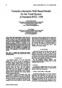
7th ΙΕΕΕ Int. Symposium on Object-oriented Real-time Distributed Computing, ISORC’04, Vienna, Austria 2004 “©2004 IEEE. Personal use of this material is permitted. However, permission to reprint/republish this material for advertising or promotional purposes or for creating new collective works for resale or redistribution to servers or lists, or to reuse any copyrighted component of this work in other works must be obtained from the IEEE.”
Towards an Implementation Model for FB-based Reconfigurable Distributed Control Applications K. Thramboulidis, G. Doukas, A. Frantzis Electrical & Computer Engineering, University of Patras, 26500 Patras, Greece
[email protected],
[email protected] Abstract
Advances in software technologies may facilitate the development and deployment of complex control systems. In [1] three possible directions for the development of distributed control systems are discussed: a) UML-based approaches, b) Function Block-based approaches and c) hybrid approaches integrating UML with the Function Block (FB) concept. According to the first approach, the standard UML notation is used to produce the models of the control system [2][3]. The big disadvantage of this approach is that it is completely new for practitioners in control and automation. Control engineers are mainly accustomed with concepts and languages defined by the International Electro-technical Commission (IEC). The FB-based approach, which is the one proposed by evolving IEC standards such as 61499 [4] and 1804 [5], is based on the FB concept. Although many researchers are already working on different aspects of the IEC proposal [6][7], the absence of tools and products that are compliant with this approach is evident. The Function Block Development Kit (FBDK) by Rockwell Automation [8] and CORFU-FBDK [9] are the only known tools supporting this approach. The big advantage of this approach is that it exploits the experience of industry’s practitioners and easily integrates the big number of existing legacy applications and systems. However, it does not exploit all the benefits of object and component technologies. Finally, the hybrid approach integrates the UML notation with the function block concept. However, this integration is done from different perspectives. Brennan et al. in [10] describe two approaches for modelling decentralized Manufacturing Systems with UML-RT capsules [11]. They propose the construction of models of the control system at the conceptual level using UML-RT. They next proceed to the mapping of UML-RT to IEC61499 models which are considered as implementation models. However, it is quite difficult for control engineers to model in UML-RT and FB diagrams are design models. Thramboulidis and Tranoris in [12][13] consider the use of the UML notation in the requirements specification phase utilizing a use case driven approach. The UML-based requirement
The Function Block (FB) has been defined by the International Electro-technical Commission (IEC) as the basic construct for the development of reusable, interoperable, distributed control applications. Complete applications can be defined in the design level as networks of interconnected FBs. For these design models to be automatically converted to implementation ones, adopting the model integrated computing paradigm, an appropriate implementation meta-model should be defined. In this paper we describe two alternatives for the implementation of FB design models. The first one adopts the straightforward transformation of the FB design model to a high level language (C++, Java) implementation model. The second approach utilizes UML-RT models as an intermediate representation towards the final implementation model. Both approaches support the dynamic re-configuration of the control application and exploit our extensions to the IEC Execution Control Chart notation, to improve the expressiveness of the design model and the efficiency of the implementation one.
1. Introduction The Object-Oriented approach has attracted the interest of researchers in control and automation from the beginning of the 90’s [1]. In the last years there has been a trend to use UML in control, industrial automation and in industrial enterprise integration. Even though a lot of papers present examples of using object-orientation and UML in control applications, there is a wide gap between state-of-the-art in software engineering and state of practice in the control application domain. Today’s control applications are usually developed in the form of large monolithic software packages that are difficult to be maintained, modified, and extended. The engineering tools used in the development processes address a little, or not at all, dimensions such as modularity, flexibility, extensibility, reusability, and interoperability.
1
7th ΙΕΕΕ Int. Symposium on Object-oriented Real-time Distributed Computing, ISORC’04, Vienna, Austria 2004
(DCSs). These standards define also the ways that FBs can be used to define robust and re-usable software components that constitute complex DCSs. Complete control applications, can be built from networks of function blocks, formed by interconnecting their inputs and outputs. The FB, as redefined by the IEC61499, is a functional unit of software, comprising an individual, named copy of the data structure specified by the function block type, which persists from one invocation of the function block to the next [4]. It consists of a head and a body, where the head is connected to the event flows and the body to the data flows. The functionality of the function block is provided by means of algorithms, which process inputs and internal data and generate output data. The FB shares many of the well defined and already widely acknowledged benefits of the object concepts introduced by object technology.
specification models are next automatically transformed to FB-based models that are used in the deployment process of the control application. However, none of the above researchers has proposed a way for implementing the FBbased design specifications of control applications. Brennan et al. even though present in [10] an Operating System that allows the execution of function block based control applications, they do not describe the used implementation meta-model. In this paper we describe two alternatives for implementing FB-based design models. The first approach is based on a straightforward transformation of the FB design model to a high level language (C++ or Java) implementation model. RTLinux was used to examine the applicability of this approach. The second approach utilizes UML-RT models as an intermediate representation towards the final implementation model. Both implementation models support the dynamic reconfiguration of the control application. However, the later is more flexible since it utilizes the automatic code generation feature of commercial CASE tools to automatically derive the implementation model of the control application. To improve the expressiveness of the FB-based design model and the efficiency of the implementation one, we propose two extensions to the IEC notation. We introduce the concept of transitory state and allow for algorithms to generate output events. Both prototype code generators are under development and will be integrated in CORFU FBDK, an IEC-compliant Engineering Support System. The remainder of this paper is organized as follows: In the next section, we briefly refer to the IEC61499 model and the CORFU FBDK as a reference implementation of this IEC standard. In section 3, extensions to the IEC notation for the Execution Control Chart (ECC) are presented. In section 4, we present the architectural model of the supporting execution environment for both implementation models. In section 5, two alternatives for the implementation model are presented. We emphasize the use of UML-RT as an intermediate representation in our model transformation approach towards the implementation model. Finally we conclude the paper in the last section.
2.2. CORFU FBDK In the context of the CORFU project we adopted the IEC61499 model and we were guided in the definition of the CORFU framework [14] and to the design and development of a new generation CASE tool (or Engineering Support System according to 61499) that is highly required to support the whole life cycle of FBbased IEC-compliant control applications [13]. Such a tool should support the engineer, according to the IEC61499 standard, in the analysis, design, implementation, and configuration phases. However, while working with the IEC-standard for the development of such a tool, we found [15] that this standard does not fully specify: a) the development process; for example the way that requirements are captured and translated to function block design diagrams, and b) communication services that are required to distribute, configure, and control the operation of FB-based control applications. We also found that a number of modifications are required to improve the IEC development process in terms of reliability, development time, and degree of automation. To address these issues, we defined: 1. a process for the development of distributed control applications [13], 2. the CORFU framework, to fulfil the requirements imposed by the above process from the fieldbus, field device and the communication subsystem levels, [14] and 3. a 4-layer CORFU architecture, to exploit current software engineering practices through the IEC61499 model [15]. The above actions have resulted in a number of artefacts that constitute the infrastructure required for the development of CORFU FBDK. The tool allows the integration of the FB concept with the UML notation in order to simplify and strengthen the development process
2. The IEC61499 function block model 2.1. The IEC61499 standard The Function Block is a well-known and widely used construct by control engineers. It was first introduced by the IEC1131 standard on programming languages for programmable logic controllers. Evolving standards, such as 61499 and 1804, extended it so as: a) to address interoperability and re-usability issues of complex distributed control systems, and b) to be used as the basis of an open standard for distributed control systems
2
7th ΙΕΕΕ Int. Symposium on Object-oriented Real-time Distributed Computing, ISORC’04, Vienna, Austria 2004
during the execution of the associated actions. At least one transition fires after the execution of the associated actions without the need for an external event. Naming of transitory states is optional. Normal states, including the initial state, as defined by IEC61499, have no associated actions. All outgoing transitions of normal states are fired by events. Figure 3 shows the ECC of BeltFB FB type, expressed in our extended notation. We use colors to discriminate the kind of state.
of distributed control applications. Use cases are used to capture the requirements of the specific control application. UML models are next used to capture the structure and the dynamics of the system. A set of Transformation Rules enables the transition from UML diagrams to FB design diagrams. A detail description of CORFU FBDK can be found in [13] and a prototype implementation can be downloaded from [9].
3. Extending the IEC61499 notation for ECC The dynamic behaviour of the FB as well as the sequencing of the FB’s algorithms invocation is specified by the ECC. According to the IEC61499, an ECC is composed of EC states, EC transitions and EC actions as shown in Fig. 1b. However, while working with function block design diagrams and their implementation we noticed a number of constraints imposed by the current notation especially in the case where devices with processing unit and RTOS support are considered as implementation environments. In such cases, FB algorithms may be expressed in languages such as C, C++ or even Java. These constraints were probably imposed in the IEC61499 model since the model was introduced as an evolution of the IEC61131 standard. We propose two extensions that will make the ECC model more expressive and result in a more efficient implementation model. The first one concerns EC states and the second EC actions. To illustrate the proposed extensions we are using as running example our Teabag Boxing system (TBS) case study. TBS is a simplified version of a real system used in the production chain of packed teabags. The system receives teabags from a teabag producer, checks their weight and forwards them either for packaging to a valid-teabag consumer, or for recycling to an invalid-teabag consumer. TBS is composed of: a) a scale, for weighing teabags, b) a feeder, for rejecting out-of-range teabags and c) 3 conveyor belts for moving teabags. Fig. 1a shows the IEC61499 graphical representation of BeltFB, which represents the FB type that captures the control logic of a conveyor belt. INIT, OBJ_ARR, OBJ_LEFT and STOPI are input events for this FB. The behavior of BeltFB in response to these events is defined using the ECC of fig. 1b that is drawn using the IEC61499 notation. START is the initial state for BeltFB. The OBJ_ARR event clears an EC transition to the OBJ_ARRIVED EC state that has one associated EC action. This action is composed of the IncCounter algorithm and CNF event output.
(a) The IEC61499 representation of BeltFB Count=1
OBJ_ARRIVED
Inc. Counter CNF
Count>1
MOVEF
MOVE 1
OBJ_ARR
EC State
EC Action
INITI
STOPI
START 1
INIT
Init INITO
1
OBJ_LEFT
STOP
Initial State Algorithm Event Output
STOPO
Count>0 Count=0
OBJ_LEFT
Dec. Counter CNF
(b) The IEC61499 Execution Control Chart of BeltFB Figure 1. BeltFB FB type in IEC61499 notation.
Figure 2. ECC of BeltFB using refinement of states.
3.1. Refining the EC states
3.2. Extending the notation for the ECC actions
In order to make the ECC model more expressive we have introduced the concept of transitory state. A transitory state is an EC state that has at least one associated action. The system is in the transitory state only
According to the IEC model FB algorithms are activated by the ECC; they processes input data and generate output
3
7th ΙΕΕΕ Int. Symposium on Object-oriented Real-time Distributed Computing, ISORC’04, Vienna, Austria 2004
The FB-based control application is represented, in the form of a platform independent model, as a FB graph that describes the communication and precedence constraints among FBs. The underlying execution environment could be as simple as a single field device but it usually represent a complex distributed network of field devices and software services. Nodes of the FB graph should be allocated to field devices of the supporting execution environment. According to the IEC61499, software components allocated to a device are assigned within the device to one or more resources. However, for simplicity reasons we assume in the context of this work that each device has only one resource. We also concentrate on the implementation model of the Basic FB type. Composite FBs are left aside as they could be modelled using Basic FBs.
data but there is no possibility to set output events. We use an example to show that this constraint results in more complicated models. Let’s consider the definition of a FB that processes the temperature of a sensor and generates the events HIGH and XHIGH. Following the trivial solution in the definition of TempAlarmFB, the FB algorithm updates the internal output data “high” and “xhigh” and the ECC produces the event CNF that notifies the consumer of the above data that they are ready for use. The graphical representation of the TempAlarmFB FB type is shown in fig. 3a.
(a) (b) Figure 3. Graphical representation of TempAlarmFB
Figure 5. ECC of TempAlarmFB (extended notation) To allow a flexible deployment, re-deployment and reconfiguration of control applications, even during runtime, we should satisfy the following core requirements: a) the ability to create new FB types during runtime, b) to create new instances for these FB types, and c) to create new event and data interconnections or change existing ones. The first two will be confronted in the next section where we define the implementation model. The third one is satisfied by the proposed execution environment of the IEC compliant device whose architecture is shown in figure 6. According to this architecture, the supporting execution environment consists of the following basic components: a) a Deployment Management Entity (DME), b) an Event Connection Manager (ECM) c) a Data Connection Manager (DCM) d) a FBType Repository and e) a set of FB Containers (FBC). We introduce the concept of the FB-container (FBC) in order to obtain dynamic re-configuration. ECM and DCM are used to obtain a flexible and re-configurable implementation scheme for both inter-FB and intra-FB connections. FBC is defined as an active component with its own thread of execution and offered QoS. FB instances are injected into FBCs during the deployment process of the FB graph. More than one FB instances may be injected into a FBC taking into account that there is only one
Figure 4. ECC of TempAlarmFB A more effective approach using the existing IEC notation is to modify the ECC so as to produce the events HIGH and XHIGH, as shown in figure 3b. However, in this case we have embed in the ECC, as is shown in Fig 4, part of the logic that has already been captured by the algorithm, increasing the redundancy and decreasing the FB’s performance. To avoid these problems we propose for the algorithms to have the possibility to generate events (one or more) without modifying the way that these events are issued by the FB head. Fig. 5 shows the definition of TempAlarmFB using the proposed extension. We have to select between the following alternatives: a) show in ECC only the events that are produced by the ECC, and b) show in the ECC all events either produced by the ECC or by the algorithms. In this later case a way to discriminate the source of the event (algorithm or ECC) is required. It must also be noticed that events produced by the ECC arise always, while events produced by algorithms may arise or not.
4. Execution environment modeling
4
7th ΙΕΕΕ Int. Symposium on Object-oriented Real-time Distributed Computing, ISORC’04, Vienna, Austria 2004
5.1. An OOP language implementation model
thread of execution per each FBC. In general, QoS required by the application model artefacts, should be satisfied by QoS offered by the supporting execution environment. FBs that should be executed in parallel must be assigned to different FBCs. Each FBC has an event queue for accepting events from the ECM. It executes a forever loop reading events from the event queue and dispatching them to the target FB instance for processing. The state machine of FBC supports the run-to-completion semantics that are critical to the reliable operation of the FB instances. The FBC also notifies: a) the DCM with the data produced by its FB instances, and b) the ECM for the events that are issued by its FB instances. Since FB instances communicate through the FBC for both events and data, they do not have any direct dependencies on the other FB instances. The ECM has been structured so as: a) to integrate for each event-input the behaviour defined by the event input state machine of the IEC61499 model, and b) to enable the system to support the event triggered model as well as the timed triggered one.
FB instances of the same FB type share the same behaviour and only differ at the data they occupy. Their behaviour is defined by the corresponding FB type. For the implementation constructs of these two types of objects we have examined the following two approaches: a) Each FB type is represented by an FBType class, which inherits the abstract class FBType that encapsulates the common structure and behaviour of FB types. FB instances are considered instantiations of the corresponding FB type class as shown in Fig. 7a. b) Two basic classes are defined: the FBType class and the FBInstance class as shown in Fig. 7b. The FBInstance class is associated with the corresponding FBType class through a ‘is of type’ association. Each FB type of the application is considered as an instantiation of the FBType class, while each FB instance is considered to be an instance of the FBInstance class. FBType
Generlization
IPCP FBType_A
FBType_B
Instantiation
fbn
En state n fb5 fb6 ...
producer FBs
fb1
fb1
fb2
fb2
fbn
fbn
Event Connection Manager
data var.
consumer FBs
D1
fb1
D2 D3
fb2
FB_Instance1 : FBType_A
...
E3 state k fb5 fb1 ...
consumer FBs
...
E2 state j fb3 fb4 ...
...
fb2
E1 state i fb1 fb2 ...
...
Deployment Management Entity
ev.var. ev.state consumed by...
...
fb1
...
producer FBs
Dn
FB_Instance3 : FBType_B
fbn
Data Connection Manager
FB_Inst ance2 : FBType_A
IntraFB Connection Table
(a) 1st approach 1
+Type
FBType FBType Repository
FB Container
FB_Instance4 : FBType_B
FBInstance
0..*
IEC61499-compliant Device
Process Interface
FBType_A_Instance_2 : FBInstance
FBType_B : FB Type
Figure 6. Architectural model for an IECcompliant field device.
FBType_B_Instance_1 : FBInstance
FBType_C : FBType
5. Moving into a platform specific model
FBType_A_Instance_1 : FBInstance
FBType_A : FBType
nd
(b) 2 approach Figure 7. Proposed implementation meta-models
For the transformation of the platform independent FB design model to a Platform Specific Model (PSM) we have investigated two approaches: a) the traditional approach that exploits the capabilities of modern programming languages such as Java and C++, and leads to an OOP language implementation meta-model, and b) the intermediate model approach, that exploits UMLRT and the capability of modern CASE tools to automatically create PSMs for UML-RT models. Both approaches support the flexible deployment, redeployment and re-configuration of control applications, even during run-time.
The first approach seems to be simpler, clearer and utilizes basic mechanisms of object oriented environments such as inheritance and instantiation in a better way than the second one. However, it has some drawbacks. It lacks some level of flexibility and introduces some implementation restrictions since it requires to be implemented in an environment that supports runtime definition (construction) of classes. This is supported in the Java implementation environment using the core reflection API of the language, but it does not work with standard C++. The second approach can be implemented in any object oriented environment and can be highly extensible.
5
7th ΙΕΕΕ Int. Symposium on Object-oriented Real-time Distributed Computing, ISORC’04, Vienna, Austria 2004
5.2. Using UML-RT in the model transformation process
Further more, it is both adaptable and powerful. We next describe our work towards the implementation of the second approach. Fig. 8 shows the structural models of FBType and FBInstance classes that were used for the development of our prototype implementation model in RTLinux. FBType encapsulates all the information needed to construct FB instances of the specified type. It describes the FB interface (inputs, outputs), the internal variables of the FB instance and its behaviour in terms of ECC and algorithms. This information is utilized by the constructor of the FBInstance class to create FB instances of a given type. FB instances just store the values for the variables of the corresponding FB type. At any time the functionality of each function block is depicted by its current state in conjunction with its private variables and the ECC stored in the associated FBType class. Our prototype C++ implementation in RTLinux seems to satisfy both re-configurability and meet temporal specifications. The ‘kernel module’ mechanism of Linux is used for the runtime loading of FB types. Even though RTLinux has some dynamic memory allocation restrictions during execution of applications, we confronted these restrictions utilizing memory and thread pools. FBInstance
0.. * value
VarInstance InputEvent
0..*
invokeECC() getDataOut() setDataIn() getEventOut() setEventIn()
0..*
OutputEvent
+type
name type (FBType) current_state
EventInstance
Modelling constructs of IEC61499 have quite similar semantics with UML-RT constructs. This enables the transformation of FB design diagrams to equivalent UMLRT design diagrams. The most important task for this transformation is the definition of the FB transformation. We next describe the FBCapsule capsule, which has been defined to represent the semantics of the IEC61499 active basic FB. Classes may be used to represent passive FBs to improve the efficiency of the system, but this mapping is still under investigation. The class diagram of Figure 9 shows the composition structure of the FBCapsule, which we utilize as a template for the transformation of application network’s FBs to capsules of the resulting implementation model defined in terms of UML-RT constructs.
value
FBType InputVar
OutputVar
InternalVar
name
Figure 9. Composition structure of the FB capsule template 0..*
0..*
Algorithm
EventDeclaration
name Language FunctionBody
name Type
OutputEvent
1.. *
Input Event 1..*
InputVariable With vars
InternalV ariable 0..*
0..* OutputVariable With var
ECC
0..* 1..*
1..*
0..*
ECAction 0..*
Figure 10 shows FBCapsule’s structural containment and its communication relationships. We have mapped: a) the input and output events of the FB to the EventPort port, b) the input and output data of the FB to the DataPort port, c) the internal data and events of the FB to corresponding classes d) the algorithms of the FB to operations of the FBBody class and d) the head of the FB to the FBHead subcapsule. We have also adopted, as in [16], a port for the configuration of the resulting capsule. As shown in figure 11, FBCapsules communicate through the DataPort and EventPort end ports with DCM and ECM capsules, which are used for the realization of FBs’ data and event connections of the FB diagram. The FBcapsule reads input data and writes output data through the DataPort and accepts the EventArrived(EventId) message and sends the RaiseEvent(EventId) message through the EventPort.
VarDeclaration 0.. * name Type ArraySize InitialValue
ECS tate name
0..*
0..* ECTransition source
Condition
0..* destination
Figure 8. Structural models for FBType and FBInstance classes.
6
7th ΙΕΕΕ Int. Symposium on Object-oriented Real-time Distributed Computing, ISORC’04, Vienna, Austria 2004 t2
t1 S0
S2
S1 t4
t3
Figure 13. ECC operation state machine The lower half of the ECC operation state machine has been embedded in the FBHead abstract subcapsule, the behaviour of which is described by the state diagram of figure 14. This state diagram is abstract since it represents the common behaviour of the FBHead subcapsule of any FB capsule. Different FB capsules have different detailed behaviours in the “EvaluateECCTransition” abstract state. This state is refined during the construction of the implementation model and its substates are directly produced from the ECC of the corresponding FB. In order to illustrate how the dynamic behavior of a FB, which is expressed in terms of an ECC, is translated to dynamic behavior of a corresponding FBHead capsule expressed in terms of a state diagram, we present as an example the transformation of BeltFB FB from our TBS case study.
Figure 10. Structural containment and communication relationships of FBCapsule.
Figure 11. Structure of control application (single device view) The FBHead subcapsule communicates with the outer FBCapsule only through the EventNotificationPort (Fig. 10). The signals that can be exchanged through this port are: 1. EvaluateTransitions, which is sent from FBCapsule to the FBHead, 2. NoTransitionClears, which is sent by the FBHead to FBCapsule. The behaviour of our FBCapsule is depicted in the state diagram of figure 12. This state diagram captures the semantics of the upper half of the ECC operation state machine of the IEC61499 that is shown in figure 13.
Figure 14. State diagram of the abstract FBHead subcapsule. Translating the extended ECC diagram of BeltFB to UML-RT state diagram we obtain the state diagram of figure 15 that expresses the behaviour of the FBHead subcapsule of BeltCapsule. The model transformation could automatically be produced by the CORFU FBDK and the resulting description is automatically embedded in BeltCapsule’s specification in Rose RT. In the state diagram of figure 15, where we have embedded the common behaviour expressed by the state diagram of fig. 14, we have used comments to show the conditions and actions for each transition, since Rose RT does not display them in the graphical representation of the state diagram. However, all this information is embedded in the model and can be used in the subsequent code generation process that is supported by Rose RT. The response of FBCapsule to the EventArrived signal coming through the EventNotificationPort is the following: a) updates the event input variables to reflect the external event inputs, b) samples the input data variables related to the accepted event(s), c) sends an
Figure 12. State diagram of FBCapsule
7
7th ΙΕΕΕ Int. Symposium on Object-oriented Real-time Distributed Computing, ISORC’04, Vienna, Austria 2004
the dynamic re-configuration of the control application. However, using UML-RT as an intermediate model in the process of generating the implementation model, results in a more powerful and flexible model transformation process since it: a) utilizes the automatic code generation feature of commercial CASE tools to automatically derive the implementation model of the control application, b) supports more target platforms, c) increases the portability of the design models, and d) constitutes the first step towards the use of Real-Time UML based model analysis tools for performance and schedulabilty requirements[17]. Although our intention was to be fully compliant with the IEC61499 standard, we found that the standard imposes some constraints that influence the expressiveness of the design specification and, provides overhead to the implementation model. We were guided to propose two extensions to the IEC’s ECC notation to address these problems and facilitate the model transformation process. We introduced the concept of transitory state and provided for algorithms the possibility to generate output events. Our future work involves the automation of the whole model transformation process.
InputMapped signal to the ECM and d) sends an EvaluateTransitions signal to the FBHead subcapsule. From this point on, the FB capsule, supporting the run-to-completion semantics, does no longer accept input events. The EvaluateTransitions (EvalTrans) signal activates the FBHead subcapsule (see fig.14) which checks whether any outgoing transition in the active state is fired. If so, the transition is activated and its destination state is activated. The final action of almost any transition is to re-send, the EvaluateTransitions signal so as to cause the state machine to check the outgoing transitions of the active state. This is mandatory since in the ECC, transitions in the current state are continuously checked until there is no active transition, whereas in UML's state diagrams a new event must occur for the transitions to be checked. This approach also addresses the problem that arises from the absence of NULL (“1”) transition in UML's state diagram that is supported by the ECC semantics. When a state without an active outgoing transition is reached, the always firing self-transition is triggered for that state. This virtual self-transition is adopted to obtain the posting of the NoTransitionClears signal to the outer capsule. It must be noticed that the virtual self-transition does not post an EvaluateTransitions signal to the ECC subcapsule and therefore the execution of the state diagram is terminated. A virtual self-transition is only required for the states that have not a transition that is active at any time.
7. References [1]
[2]
[3] [4]
[5]
[6]
[7]
[8] [9] [10]
Figure 15. State diagram of the FBHead subcapsule of the BeltCapsule.
6. Conclusions
[11]
In this paper, two alternatives for the implementation of FB-based IEC61499-compliant distributed control applications have been proposed. Both approaches support
[12]
8
K. Thramboulidis, “Unified Modeling Language: The Industry Standard for Object-Oriented Development”, chapter in Industrial Information Technology Handbook, CRC Press, (forthcoming). Douglas, B., Doing Hard Time: Developing Real_time Systems with UML, Objects, Frameworks, and Patterns, Addison Wesley 1999. Gomma, H. Designing Concurrent, Distribute, and RealTime Applications with UML, Addison Wesley 2000. IEC Technical Committee TC65/WG6, IEC61499 Industrial-Process Measurement and Control – Specification, IEC Draft 2000. IEC Technical Committee No. 65C: Digital Comm., WG 7: Function blocks for Process Control , IEC1804 General Requirements, IEC Draft 1999 Vyatkin, V., H.Hanisch, “Formal-modelling and Verification in the Software Engineering Framework of IEC61499:a way to self-verifying systems”, ETFA’01, Nice, October, 2001. Brennan, X., X. Norrie, “Agents, holons and function blocks: distributed intelligent control in manufacturing”, Journal of Applied System Studies, 2(1) (2001), 1-19. Rockwell Automation, FBDK, http://www.holobloc.com/fbdk/README.htm CORFU-FBDK, http://seg.ee.upatras.gr/corfu/ Brennan, R, et al. “Comparing two Approaches to Modelling Decentralized Manufacturing Control Systems with UML Capsules”, Proceedings of the 13th IEEE International Workshop on Database and Expert Systems Applications, Sept. 2-6, 2002, France. B. Selic, Rumbaugh, J. “Using UML for Modeling Complex real-Time Systems”, Rational Software, 1998. Thramboulidis, K. “Using UML for the Development of Distributed Industrial Process Measurement and Control
7th ΙΕΕΕ Int. Symposium on Object-oriented Real-time Distributed Computing, ISORC’04, Vienna, Austria 2004
[13]
[14]
[15]
[16]
[17]
Systems”, IEEE Conference on Control Applications (CCA), September 2001, Mexico. K. Thramboulidis and C. Tranoris, “Developing a CASE Tool for Distributed Control Applications”, International Journal of Advanced Manufacturing Technology (forthcoming). K. Thramboulidis, “Development of Distributed Industrial Control Applications: The CORFU Framework”, 4th IEEE Intern. Workshop on Factory Communication Systems, August 2002, Sweden. K. Thramboulidis, “Towards an Engineering Tool for Implementing Reusable Distributed Control Systems”, 9th ESEC & 11th SIGSOFT FSE, Sept. 2003, Helsinki. R. Brennan, et al. “An Agent-Based Approach to reconfiguration of Real-Time Distributed Control Systems”, IEEE Transactions on Robotics and Automation, vol.18, No.4, August 2002. OMG, “UML Profile for Schedulability, Performance, and Time Specification, Ver. 1.0, September 2003.
9