speed and scale not possible with a real implementation. DCSim [1], [2] is ... II presents related work in data centre simulation, Section III ...... We plan to include a.
Towards an Improved Data Centre Simulation with DCSim Michael Tighe, Gast´on Keller, Jamil Shamy, Michael Bauer and Hanan Lutfiyya Department of Computer Science The University of Western Ontario London, Canada {mtighe2|gkeller2|jshamy|bauer|hanan}@csd.uwo.ca Abstract—Computing is increasingly moving into large-scale data centres, providing resources on-demand for clients on a payper-usage basis. One form of such on-demand computing is an Infrastructure as a Service (IaaS) Cloud, which provides low level access to virtualized resources. Developing and evaluating data centre management techniques for such large-scale data centres presents a significant challenge. As such, most work turns to simulation tools as the test environment. We present a number of extensions and additional features to an existing simulation tool, DCSim. Our improvements to DCSim include work on the core of the simulator, improved event, communication and management mechanisms, and a more complete model of the structure of a data centre. We also present improved simulation configuration tools and output, including a unique visualization tool. We evaluate the usefulness of the simulator through a demonstration of its use in comparing dynamic VM management techniques. Keywords—Cloud, Data Centre, Simulator, Virtualization, Infrastructure as a Service
I.
I NTRODUCTION
Computing is increasingly being moved into large-scale data centres, providing resources on-demand for clients on a pay-per-usage basis. One form of such on-demand computing is an Infrastructure as a Service (IaaS) Cloud, which provides low level access to virtualized resources. Virtualization allows for multiple virtual machines (VMs) to be co-located on a single physical machine (host), providing the ability to achieve increased host utilization. By utilizing host resources as much as possible, client workloads can be consolidated on the fewest number of hosts possible in order to conserve power and provide services to a larger number of clients. Resources, such as CPU, can be oversubscribed to further increase host utilization, but this comes with the risk of exhausting the resources on a host, causing VM performance degradation. In order to consolidate VMs to conserve power while providing the resources VMs require to perform up to client expectations, VMs must be dynamically managed. Dynamic VM management, along with related topics in data centre management, is a hot area of research. The scale of data centres providing Cloud services continues to increase, with thousands to tens-of-thousands of servers to manage. This presents a unique challenge to researchers developing methods and algorithms for management, as the scale of the target environment precludes the use of a physical testbed. As such, simulation is commonly used for the evaluation of management techniques. Simulation also helps ISBN 978-3-901882-53-1, 9th CNSM 2013: Workshop SVM 2013
364
researchers quickly evaluate and fine-tune algorithms at a speed and scale not possible with a real implementation. DCSim [1], [2] is a simulation tool for simulating a virtualized data centre operating as an IaaS Cloud. To support our current research [3] and planned future work, and to provide tools that other researchers can leverage in their work, we have developed a number of extensions and improvements to DCSim. This includes work on the core of the simulator to provide more flexibility, improved Event class structure and mechanisms for event callbacks and sequencing, new components to simplify the creation of management systems and to model the communication between them, and a more complete model of the structure of a data centre including racks and clusters. We also introduce classes to help streamline the creation of new experiments, new output options and metrics, and a visualization tool to help provide a new perspective on the behaviour of data centre management methods and systems. Finally, we continue to focus on providing an extensible platform for researchers to extend to suit their own work. In areas of DCSim that have not seen additional development, we provide a more detailed explanation of its underlying mechanisms. The remainder of the paper is organized as follows: Section II presents related work in data centre simulation, Section III describes the architecture, core features and new additions to DCSim, Section IV gives some detail on how to configure and run experiments with DCSim, Section V provides an evaluation of the simulator through a demonstration of its use, and Section VI presents some conclusions and future work. II.
R ELATED W ORK
There are a small set of existing simulation tools available, each with their own strengths, weaknesses, and target environments. GreenCloud [4] is designed to evaluate the energy costs of operating a data centre. It is a packet-level simulator built as an extension to Ns-2 [5], and provides a detailed model of communication hardware and power consumption of each element of the data centre. It does not, however, include modelling of virtualization. MDCSim [6] is designed to simulate a large-scale data centre running a three-tiered web application. It focuses only on evaluating the configuration of each tier, measuring both power and performance metrics. As with GreenCloud, it does not consider virtualization. Furthermore, it is built on a commercial product and is not publicly available.
GDCSim (Green Data Centre Simulator) [7] aims to help researchers fine-tune the interactions between management systems and the physical layout of the data centre, including thermal and cooling interactions with workload placement. This tool does not consider multiple tenants of the data centre, nor does it consider virtualization. CloudSim [8] simulates a virtualized data centre, with multiple clients operating VMs. However, it implements an HPC-style workload, with Cloudlets (jobs) submitted by users to VMs for processing. It can be manipulated to simulate an interactive, continuous workload such as a web server [9], but it lacks a real model of such an application. An extension of CloudSim, NetworkCloudSim [10], considers communication costs between VMs performing parallel computations, but again focuses on HPC-style workloads rather than interactive workloads. Additionally, our work on DCSim adds data centre organization components such as racks and clusters not present in CloudSim. SimWare [11] targets the modelling of data centre cooling and power costs, including the impact of server fan power consumption as related to the temperature of the data centre, and air travel time from CRACs to servers. Their simulated client workload is based on traces of HPC systems, rather than interactive applications. DCSim [1], [2] models a virtualized data centre providing IaaS to multiple tenants, with a focus on interactive workloads such as web applications. It can model replicated VMs sharing incoming workload, as well as dependencies between VMs that are part of a multi-tiered application. It also provides metrics to gauge SLA violations, power consumption, and other performance metrics that serve to evaluate a data centre management approach or system. Furthermore, DCSim is designed to be easily extended, implementing new features and functionality. This work presents new built-in features for DCSim, as well as new modifications to the underlying simulator to provide more flexibility for future extensions. III.
DCS IM A RCHITECTURE & C OMPONENTS
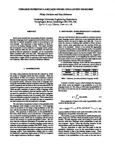
DCSim is an event-based simulation tool, written in the Java programming language. It is designed to be easily extended to include new features and functionality, so as to support research in the area of data centre management. Figure 1 gives a high-level overview of the basic data centre model implemented by DCSim. The remainder of this section outlines the components and underlying mechanisms that drive DCSim, as well as new features and improvements which have been recently added to the simulator. A. Simulation Engine As DCSim is intended to be a simulation platform that can be extended to suit the needs of a particular area of research, it is useful to take a look at the mechanism by which DCSim advances through simulated time in order to help gauge the feasibility of possible extensions. Furthermore, we have enhanced the functionality of DCSim by adding a post-scheduling hook whereby data centre components can create new events or move existing events based on dynamic resource scheduling. This allows the simulation of operations and processes that exhibit variable runtime based on available ISBN 978-3-901882-53-1, 9th CNSM 2013: Workshop SVM 2013
365
Fig. 1: Data Centre Model
resources. This feature is included primarily for the planned future development of variable VM migration times (due to changes in available network bandwidth), and batch/HPC type jobs whose runtime is based on dynamically scheduled CPU. Algorithm 1 outlines a simplified version of the main simulation loop. 1: 2: 3: 4: 5: 6: 7: 8: 9: 10: 11: 12: 13: 14:
simT ime = 0 while eventQueue not empty && simT ime ≤ duration do scheduleResources() postScheduling() e = peek(eventQueue) simT ime = e.getTime() advanceSimulation(simT ime) updateMetrics() performLogging() while eventQueue not empty && peek(eventQueue).getTime() = simT ime do e = pop(eventQueue) handleEvent(e) end while end while Algorithm 1: Main Simulation Loop
The eventQueue contains all future events that must be executed, simT ime records the current simulation time, and duration is the length of the simulation (in simulation time). The outer loop is responsible for advancing in simulation time to the next scheduled event(s). Changes to data centre state only occur via events; in-between events, the state of the data centre is static. The first phase of the loop uses the current data centre state to schedule resources (line 3), in which an allocation of resources/second for each VM is calculated (see Section III-F). CPU scheduling is based on current application demands, in a fair-share manner up to the maximum capacity of the Host processor. Next (line 4), data centre components get a chance to create or revise future events based on the newly calculated
resource scheduling. We then check for the simulation time of the next event (which may have changed based on processing in postScheduling()), and advance the simulation to the time of the next event using the calculated resource scheduling (lines 6 & 7). Simulation metrics are then updated (see Section IV-B) and logging is performed. The inner loop (lines 10 to 13) executes all events that take place at the current simulation time. The process is then repeated to advance to the next set of events. B. Events As DCSim is an event-driven simulation, all actions, operations and state changes in the simulation are triggered by an Event. Events are also used for communication between data centre elements and management components. The basic properties of an Event are the simulator component(s) that will receive the Event, and the time at which to execute it. Events are ordered such that, in the case of multiple Events being executed at the same simulation time, they are executed in the order in which they were sent. Any component can send an Event to another component, or to itself in order to trigger some functionality at a specific time in the future. The basic Event class is abstract, with specific Event types implementing any behaviour or storing any data they require. There are a number of hooks and methods which can be used to add additional functionality to an Event. Pre-execution and post-execution methods can be implemented to perform operations before and after the Event is executed, such as logging Event details. An Event Callback can also be registered with an Event, allowing one or more objects to be notified once an Event has been executed. In some cases, an Event can cause several other Events to be generated in order to complete an operation, which may require the post-execution and callback methods to be triggered only after the complete sequence of Events has been executed. To accomplish this, Events can be strung together in a sequence. For example, instructing a Host (i.e., a server; see Section III-C) to boot up involves one Event sent to the Host, and another Event sent by the Host to itself some time later indicating the completion of the operation (Hosts take time to boot). These Events are added in sequence together, allowing a management component to receive a callback only once the full boot up operation has completed. A special Event subclass, MessageEvent, can be used for communication between components by extending it with any additional functionality required. MessageEvent automatically keeps track of the number of messages of each specific subclass that are sent during the simulation. Finally, a special type of Event, called the RepeatingEvent, can be used to trigger repeated executions of the Event on a regular interval. C. VMs, Hosts, Racks & Clusters DCSim uses a series of abstractions to organize the architecture of a data centre. These abstractions are VM, Host, Rack, Cluster and DataCentre. In DCSim, a data centre consists of a collection of clusters, each cluster being a collection of racks, and each rack a collection of hosts. Both Cluster and Rack are designed to be homogeneous collections (in terms of their composing elements), but DataCentre may be an heterogeneous collection. ISBN 978-3-901882-53-1, 9th CNSM 2013: Workshop SVM 2013
366
1) VM: A VM in DCSim represents a virtual machine running a single application. The properties and requirements of a VM are defined in its VMDescription, which is used to create an instance of the VM. The VMDescription defines the number of virtual cores and the amount of CPU, memory, bandwidth and storage resources requested. In its present state, DCSim allocates memory, bandwidth and storage statically to a VM, in the full requested amount (they are not oversubscribed). CPU resources, however, do not need to be fully allocated, allowing a host CPU to be oversubscribed. Once a VM is created and started on a host, its CPU requirements are driven dynamically by the needs of the application it is running (See Section III-E for details on applications in DCSim). In order to perform dynamic management of VMs in a data centre, VMs must be moved from one Host to another using VM Live Migration. VM Live Migration allows a VM to be moved to another physical machine with minimal downtime. DCSim supports simulating VM Live Migration, and calculates the time to migrate a VM based on available bandwidth and VM memory size. 2) Host: A host represents a physical machine in the data centre, capable of running VMs. Its physical properties are defined by the following set of attributes: the number of CPUs; the number of cores per CPU; core capacity; memory capacity; network capacity; storage capacity; and a power model. Core capacity is defined in terms of CPU Units, where one CPU unit is equivalent to 1MHz of processor speed (e.g., a 2.4GHz processor has 2400 CPU units). The power model defines how much power the host consumes at a given CPU utilization level, and is calculated using results from the SPECPower benchmark [12]. The resource utilization of the host at any given time is calculated as the sum of the resources in use by the set of VMs it is hosting (including its privileged domain). A host can be in one of three states: on, off, or suspended. VMs are only given resources to run their applications when the host is in the on state. The host consumes some small amount of power when in the suspended state, and no power when off. Transition times between states can be defined in the simulation configuration file. 3) Rack: A rack represents a collection of hosts in the data centre. This collection is homogeneous; that is, all hosts in the rack are of the same type. A rack has a given number of slots that can be filled with hosts, and this number may vary between racks. A rack counts also with two switches to which every host in the rack is connected. 4) Cluster: A cluster represents a collection of racks in the data centre. This collection too is homogeneous. The number of racks per cluster is not fixed, so different clusters can have different numbers of composing elements. The cluster also contains two collections of switches, one for the data network and one for the management network (more information on networks in the next section). D. Data Centre Network In DCSim, a data centre has two different networks: a data network and a management network. The first is used to meet the communication needs of the hosted VMs, while the second is used for the internal management of the data centre. VM migrations make use of the management network
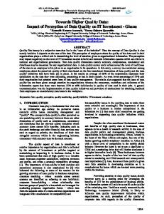
Fig. 2: Application Model
as do status update messages or migration requests exchanged between management entities. A network consists of nodes and edges, namely, NetworkElement objects and Link objects. A Link has a certain bandwidth capacity and it connects two NetworkElement objects. There are two types of NetworkElement: NetworkCard and Switch. Every Host has two network cards, one for each network. These network cards are connected through links to their corresponding switch in the rack (two switches per rack, one per network). At cluster-level, two network arrangements are possible: one, every rack in the cluster is connected to a single switch (per network), which is referred to as main switch and requires as many ports as there are racks in the cluster; and two, there is a two-level hierarchy of switches (per network), where racks are connected to low-level switches and low-level switches are connected to a single high-level switch (referred to as main switch). At data centre-level, there is a central switch (per network) to which each cluster’s main switch is connected. E. Application Model Each VM in DCSim runs a single Application. The Application determines the current resource requirements of the VM, and records whether or not these requirements have been met. Application is an abstact class, extended to model different types of applications, such as interactive applications and batch/HPC style jobs. At present, DCSim has only an interactive application model (such as a web application), although short-term future work includes the addition of a batch/HPC application model. In the interactive application model (Figure 2), we define a Service as a set of one or more application instances cooperating together to provide a specific service to a set of clients, coupled with a Workload component which defines the current (dynamic) level of incoming workload (i.e. requests). A Service is composed of at least one Service Tier. We define a Service Tier as a set of identical Application instances, running each within their own VM, which split incoming workload via a Load Balancer element. Multiple Service Tiers within a Service are ordered, whereby the amount of work being completed by one tier is used as the input level for the next tier. The Workload component defines the level of incoming work at any given time in the simulation, akin to requests per second. The Application uses this incoming workload level ISBN 978-3-901882-53-1, 9th CNSM 2013: Workshop SVM 2013
367
to calculate the amount of CPU resource it requires, which is calculated linearly using a specified number of CPU units required per unit of work. Changes in incoming workload level can be generated randomly, or can be driven by a trace. A trace specifies normalized workload levels in the range of [0, 1] at regular time intervals. We have generated a set of trace files based on freely available web server traces. We divide the original trace into equal length segments (120 second intervals), and total the number of requests received in each interval. We then normalize the values of each interval. The normalized traces can then be scaled by the Workload to any size required. The Workload component dynamically adjusts the workload level by scheduling simulation Events to update the workload level for each change specified in the trace. It may be the case that a VM does not receive the CPU resources it requires in order for its Application to meet the demand of the incoming workload. This occurs when the host is overloaded and its CPU has reached capacity. If the VM does not receive the required CPU resources, it calculates how much work it can perform with the given CPU resources, and records the percentage of work that could not be completed as the SLA Violation percentage (see Section IV-B). In the case that the Service Tier to which the under-provisioned Application(s) belongs is serving as input for a subsequent tier, only the amount of work completed is sent as input for the next tier. F. Resource Managers & Scheduling Host resources in DCSim are managed by a Resource Manager component on each Host. The Resource Manager is responsible for allocating and deallocating resources for VMs, keeping track of the total amount of resource allocated, and deciding whether or not the Host is capable of running a given VM. The Resource Manager is an abstract class and must be extended to provide the desired functionality. The default Resource Manager allocates memory, bandwidth and storage statically, with no oversubscription. CPU is oversubscribed, allocating to VMs as much CPU as they request, although they may not actually receive it if the Host CPU becomes overloaded. While the Resource Manager handles allocations, the Resource Scheduler handles the scheduling of dynamic resources, such as CPU, based on current demand. At present, the Resource Scheduler schedules only CPU, although it could be extended to dynamically calculate usage of other resources as well, such as bandwidth. Other resources are simply given their full allocation, as determined by the Resource Manager. During the schedule resources phase of the simulation loop (see Section III-A), the Resource Scheduler for each Host calculates the amount of resources/second that each VM is given. In the case of CPU, this would be the number of CPU units given to each VM. It does so in an fair-share manner, giving each VM a chance to receive an equal amount of CPU, up to the total CPU required by its application at the current time. CPU not used by one VM can be used by another, and any CPU amount required by a VM over and above the capacity of the Host is not scheduled, resulting in application performance degradation. Since the incoming workload for a VM may be determined by the resources allocated to another VM in the data centre
(i.e. in multi-tiered Services), the full set of VMs are first sorted such that if VM b receives its incoming work from VM a, then a will be scheduled first. The ordered list of VMs is then scheduled in rounds. Once the scheduling is complete, the resulting division of resources is used to calculate the amount of processing completed over a period of simulation time in the advance simulation phase of the simulation loop. G. Autonomic Managers & Policies Our development of DCSim is focused on providing tools to support research on virtualized data centre management. The Autonomic Manager (AM) and related components provide a framework to allow quick development of new management systems, while taking care of some of the messaging and event handling details of DCSim automatically. The AM acts as a container for a set of Capabilities and Policies. A Capability is simply an object that stores data and provides methods for use in one or more Policies. For example, the HostManager Capability provides a reference to a host that is managed by an AM possessing the capability. This can be used by a Policy that is designed to manage a host in the data centre. Policies are installed into AM, and implement the actual management logic. A Policy can only be installed in an AM that possesses the Capabilities that the Policy requires to function. Policies can be triggered on a regular interval, or can respond to events sent to the AM by another Policy or component. In order to design a Policy that executes on a regular interval, we simply create a Policy class that defines an execute() method, and pass the time interval to the AM when installing the Policy. To trigger a policy on the arrival of a specific Event class, we simply define an execute(ConcreteEvent e) method, and the AM will automatically detect that the Policy accepts these Events, and call the Policy whenever one is received. AMs do not need to be attached to any other component, and can simply run detached from the physical data centre infrastructure. However, they can also be attached to Host objects, to indicate that the AM is running on that Host. When this configuration is used, the AM will only execute when the Host is in the on power state.
I. Metrics DCSim includes a mechanism for recording metrics of interest in order to evaluate management systems and algorithms through simulation. All metrics extend the Metric superclass, and DCSim includes a number of specific Metric types as well as some generic types to store basic types of values, such as averages. Metrics can easily be added to the simulation in order to collect any necessary data, most often with a single line of code, and are automatically outputted at the conclusion of the simulation. IV.
C ONFIGURING AND U SING DCS IM
In this section we describe some of what is required to configure and run DCSim. A. Workloads As discussed earlier in Section III-E, the Workload component is responsible for specifying a dynamic workload level for Applications running in the simulated data centre. In our simulations, we use normalized workload traces built from 5 real web server traces: the ClarkNet, EPA, and SDSC traces [13], and two different job types from the Google Cluster Data trace [14]. To ensure that VMs do not exhibit identical behaviour, we always start the trace for each VM at a randomly selected offset time. In a data centre, the set of VMs is not static; VMs continuously arrive and depart the data centre. We have therefore implemented a new feature in DCSim which dynamically adds new Services (see Section III-E) to the data centre, which are submitted by sending a VM Submit Event containing a description of the Service to be instantiated in the data centre. Services have a lifespan chosen randomly from a specified distribution, after which they terminate. This helps model not only changes in individual VM resource requirements, but also changes in overall data centre utilization over the course of a single simulation. B. Default Metrics
Within this framework, it is a quick and simple process to define new Policies, Capabilities and Events to build a desired management system or test a management algorithm.
DCSim provides a number of useful metrics in order to help judge the performance of data centre management systems and algorithms, including the following:
H. Management Actions
Average Active Host Utilization: The average CPU utilization of all hosts that are currently in the on state. The higher the value, the more efficiently resources are being used.
Common management operations performed within a simulation can be encapsulated in a Management Action. DCSim currently features Management Actions for instantiating a new VM, migrating a VM, replicating a VM within a Service Tier, and shutting down a host. Additional Management Actions can be created by extending an abstract class. It is possible to build a set of actions which can be executed either concurrently, in sequence, or in combinations of the two. If a sequence of Management Actions is executed, the preceding Management Actions must complete before subsequent ones can execute. This includes the case where some Management Actions, such as VM migration, may take some time to complete. ISBN 978-3-901882-53-1, 9th CNSM 2013: Workshop SVM 2013
368
Max, Min, and Average Active Hosts: The maximum, minimum, and average number of Hosts in the on state at once. Number of Migrations: The number of migrations triggered during the simulation, by each management component that triggers migrations. SLA Violation (SLA V): The percentage of work that could not be completed due to resource under-provisioning. This also includes a migration overhead penalty of 10% of the current incoming work applied to VMs during migration [15].
SLA Violation Duration (SLA Duration): The total amount of time that all VMs spent in a state of SLA violation. For example, if two VMs were each in SLA violation for 5 minutes, the SLA Violation Duration would be 10 minutes.
Enable Trace: This will enable a machine-readable version of the detailed simulation data, for use in graphing or visualizations.
Power Consumption: Power consumption is calculated for each host, and the total kilowatt-hours consumed during the simulation are reported.
E. Visualization Tool
Message Counts: The number of message sent, for each subclass of MessageEvent used during the simulation. Services: The number of new Services created and submitted for instantiation to the data centre, the number of Services that end during the simulation, and the number of Service instantiations that fail due to inability to find a suitable host for placement. C. Performing Experiments with DCSim In order to make configuring and performing experiments with the simulator as clean and easy as possible, we added a set of new helper classes for performing simulations. The SimulationTask class encapsulates a single simulation configuration, allowing the user to configure the simulator by implementing the setup() method, while taking care of the details of running the simulation automatically. Simulation name, and duration can be specified, as well as a period of time to wait before recording metrics. Finally, a seed for random number generation can be passed to the SimulationTask to be used to generate any random elements, such as workload configurations. This provides repeatable experiments, which is convenient both for debugging and for comparing management systems and algorithms. Once the SimulationTask has been run, a collection of Metrics recorded during the simulation is returned. In order to run several simulations, either sequentially or concurrently, SimulationTask objects can be added to a SimulationExecutor. The SimulationExecutor handles spawning threads for individual SimulationTasks, waiting for all tasks to complete, and returning the resulting Metric collections from each SimulationTask. D. Output & Logging DCSim uses the logging library Apache log4j [16]. By default, only basic output is printed to the console, with other options available for more detailed logging (at the expense of processing time required for logging I/O). The DCSim configuration file contains several options specifying different logging output: Enable Detailed Console: This will cause detailed, humanreadable data on the execution of the simulation to be outputted to the console. This includes data on each Host and VM at every step in simulation, as well as data on management operations such as VM migration. Enable Console Log File: Console output will also be written to a log file. Enable Simulation Logging: Individual, detailed data on the execution of the simulation (the same data as enabled with the Enable Detailed Console option), will be written to a separate log file for each SimulationTask run, even if several SimulationTask objects are executed concurrently. ISBN 978-3-901882-53-1, 9th CNSM 2013: Workshop SVM 2013
369
When developing and evaluating data centre management techniques, it can be extremely helpful to have a tool to visualize what is happening within the simulated data centre. We have developed a visualization tool that makes use of the machine-readable trace output of DCSim to provide a set of graphs describing the simulation run in detail. Furthermore, it includes an animation, allowing the state of Hosts and VMs in the data centre to be viewed as the simulation time progresses. Host and VM resource utilization are presented, and VM migrations and new instantiations are clearly shown. This allows the researcher to visually see how a management system or algorithm is operating, and to gain new insight into its behaviour. V.
E VALUATION
In this section we demonstrate how DCSim can be used to implement and evaluate a management system, and use three different (though similar) management systems as working examples. We first describe the elements of these management systems (such as autonomic manager capabilities, policies, and events), discuss the changes that were made from one system to the next, and later compare the systems through simulation. A. Data Centre Infrastructure The target infrastructure consists of a collection of hosts and a DataCentre abstraction that contains all of the hosts. Each host has an associated Autonomic Manager (AM), as does the data centre. In the next sections we will discuss the capabilities of these managers and their associated policies. B. Management Systems - Common Elements Each host in the data centre has an AM associated with it. This manager possesses a capability, namely HostManager, that acts as a knowledge base for the manager, storing all relevant management information that the policies may need to successfully execute. One such policy is the HostMonitoringPolicy, which upon invocation collects the current status information of the host (resources in use or allocated, power consumption, number of incoming and outgoing VM migrations, etc.), packages the information in a HostStatusEvent message, and sends the message to the data centre’s AM. The HostMonitoringPolicy requires the HostManager capability, so as to be able to access the host and collect the necessary status information. Another policy installed in every host’s AM is the HostOperationsPolicy. This policy defines the behaviour of the manager upon receiving the events InstantiateVmEvent, MigrationEvent and ShutdownVmEvent. These events trigger the allocation of the resources requested for the VM in the host, start a migration process, and stop and deallocate a VM, respectively. At installation time, the HostMonitoringPolicy is configured to be triggered every 5 minutes. This behaviour is
achieved by creating a RepeatingPolicyExecutionEvent with a periodicity of 5 minutes and specifying the host’s AM as intended target. When the manager receives the event (once every 5 minutes), it triggers the associated policy.
exceeds the resource capacity of the host. When this happens, one or more VMs have to be migrated to another host, so as to free resources locally to satisfy the resource demand of the remaining VMs.
The data centre’s AM possesses the HostPoolManager capability, which serves to store information about a collection of hosts (in this case, all the hosts in the data centre). In the following sections we will discuss the policies that are installed in this AM.
The management system uses a VM Relocation policy to determine which VMs to migrate away from a stressed host and to choose a new host for the migrating VMs. The policy is configured at installation time to run periodically every 10 minutes. When invoked, the policy first checks the set of hosts to determine which, if any, are stressed. For each stressed host, the policy follows a greedy algorithm to select VMs for migration and to find target hosts in which to place the migrated VMs.
C. Static Management System The Static Management System allocates VMs in the data centre according to their expected peak resource demand, allocating to each incoming VM the total resources requested at creation time and never modifying that allocation. This is achieved through a single management policy, which is installed in the data centre’s AM. This policy is a VM Placement policy, which defines how to perform the mapping of incoming VMs to hosts. Every time a VmPlacementEvent is received, the data centre’s AM invokes the VM Placement policy. This policy implements a greedy algorithm to place the incoming VM in the first host that has enough resources available to fit the VM without over-committing resources. If one such hosts is found, then the search is terminated and an InstantiateVmEvent is sent to the host. Otherwise, the VM Placement fails and the client request is rejected. The policy relies on the manager’s HostPoolManager capability to get status information about all the hosts. Another policy installed in the data centre’s manager is the HostStatusPolicy. This policy is invoked every time a HostStatusEvent is received. The policy stores the new host status information in a data structure in the HostPoolManager capability of the data centre AM. D. Dynamic Periodic Management System The Dynamic Periodic Management System maps VMs into hosts based on their current resource needs. Resources such as memory, bandwidth and storage are statically allocated and never change, but the CPU is oversubscribed, therefore allowing the system to map more VMs to a host than is possible with the Static Management System. Like the Static Management System, the VM Placement policy installed in the data centre’s AM is invoked upon reception of a VmPlacementEvent. This policy is similar to the one used in the Static Management System, but since this system leverages CPU oversubscription, the policy does not require the hosts to have unallocated CPU for the incoming VM, but the policy rather checks how much CPU is actually in use in the host, and if there is enough CPU not in use, then the VM can be mapped into the host. As mentioned before, the system maps VMs into hosts based on the VMs’ current resource needs. At creation time, the requested resources are taken as the current resource needs of the VM. By oversubscribing resources, the management system can increase the resource utilization of the hosts, and therefore of the data centre as a whole. However, this strategy increases the risk of hosts becoming stressed. A stress situations occurs when the combined demand of the VMs co-located in a host ISBN 978-3-901882-53-1, 9th CNSM 2013: Workshop SVM 2013
370
The management system also uses a VM Consolidation policy to periodically consolidate VMs in the data centre, attempting to minimize the number of physical servers that need to be powered on to host VMs. This policy is installed in the data centre’s AM and is configured to be invoked every hour. Upon invocation, the policy uses a greedy algorithm to migrate VMs away of underutilized hosts and into hosts with higher resource utilization. Hosts that are emptied of VMs are then suspended or powered off, to conserve power. The same HostStatusPolicy used in the Static Management System is used here to process HostStatusEvent messages and maintain up-to-date status information about the hosts in the data centre. E. Dynamic Reactive Management System The Dynamic Reactive Management System is very similar to the Dynamic Periodic Management System, except that it triggers its VM Relocation policy on demand rather than periodically. The VM Relocation policy itself is essentially the same, with minor changes implemented to allow the policy to run as frequently as required rather than periodically. The Reactive system attempts to detect stress situations and trigger VM migrations as soon as possible, so as to reduce the SLA violations suffered by VMs co-located in stressed hosts. In order to achieve this behaviour, a new HostStatusPolicy (i.e. different from the corresponding policy from the Dynamic Periodic Management System) is necessary. This policy, known as ReactiveHostStatusPolicy, is still invoked upon receipt of a HostStatusEvent and is still responsible for updating hosts’ status information. However, once the status information of the host associated with the event is updated, the policy issues a VmRelocationEvent so as to invoke the VM Relocation policy. Upon invocation, the new VM Relocation policy first queries the VmRelocationEvent to obtain identification information of the host whose status information was recently updated. The policy then performs a stress check on the host. If the host is stressed, the policy looks for VMs to migrate away from the host and for target hosts to receive the migrated VMs. If the host is not stressed, the policy terminates its execution. F. Experimental Setup The simulated data centre for these experiments consists of 200 hosts, divided equally between two types: small and large. The small host is modelled after the HP ProLiant DL380G5, with 2 dual-core 3GHz CPUs and 8 GB of memory. The large
Static Periodic Reactive
Host Util. 46% 80% 79%
# Migs 0 10261 12508
Power 7221kWh 5056kWh 5121kWh
SLA V. 0.0% 0.109% 0.059%
SLA Duration 0 26.58 days 15.42 days
Failed Placement 24% 0% 0%
TABLE I: Management Systems Comparison
host is modelled after the HP ProLiant DL160G5, with 2 quadcore 2.5GHz CPUs and 16GB of memory. The different types of host have different power efficiency, which is calculated as CPU capacity / power consumption at 100% utilization. The power efficiency of the large host is 85.84 cpu/watt, while the power efficiency of the small host is 46.51 cpu/watt. We use three types of VMs in these experiments. The small VM requires 1 virtual core with 1500 CPU units (minimum), plus 512MB of memory. The medium VM requires 1 virtual core with 2500 CPU units (minimum), plus 512MB of memory. The large VM requires 2 virtual cores with 2500 CPU units each (minimum), plus 1GB of memory. These descriptions correspond to the resource requirements of the VMs at creation time. Once a VM is running in the data centre, further placement and allocation considerations are made based on the actual resource usage of the VM. These experiments include an equal number of each type of VM. The experiments are configured to create 600 VMs in the first 40 hours of simulation. These VMs remain throughout the entire experiment, so as to maintain a minimum level of load in the data centre. In the third day of simulation, new VMs begin to arrive; they do so at a changing rate and last for about a day. The total number of VMs in the data centre changes daily, using randomly chosen values uniformly distributed between 600 and 1600. This second set of VMs provides for a dynamic load in the data centre. We use the term workload pattern to refer to a randomly generated collection of VM instances with arrival, departure, and trace offset times. A workload pattern can be repeated by providing the random seed with which it was first generated.
Both Dynamic Management Systems achieved similar results, with Periodic showing slightly higher Host Utilization (and therefore less Power Consumption) and Reactive lowering SLA Violation and SLA Duration by about 40%. However, Reactive’s reduction of SLA Violations was achieved by triggering VM migrations as soon as hosts became stressed, which resulted in a 20% increase in the total number of VM migrations issued. VI.
C ONCLUSIONS AND F UTURE W ORK
Developing and evaluating data centre management techniques on the scale that they are ultimately required to perform at presents a significant challenge. As such, most work turns to simulation tools for their experimentation. We present a number of extensions and additional features to an existing simulation tool, DCSim [1], [2]. DCSim simulates a virtualized data centre, operating an IaaS Cloud, which allows researchers to quickly evaluate and fine-tune management algorithms at a speed and scale not possible with a real implementation. Our improvements to DCSim include work on the core of the simulator, improved Event, communication and management mechanisms, and a more complete model of the structure of a data centre. We also present improved simulation configuration tools and output, including a unique visualization tool. Finally, we have presented an example use-case of the simulator, comparing three different VM management systems, to demonstrate the usefulness of the simulation results.
G. Results
A number of additional features are planned for DCSim. An HPC/batch style application model should be included, as data centres typically host both interactive and HPC workloads. The model for interactive applications could also be enhanced to provide request response times for improved reporting on SLA related metrics.
We evaluated the three proposed management systems through simulation using DCSim. We generated 10 different workload patterns and evaluated each management system under each of these workload patterns. The experiments lasted 10 simulated days, though only the last 8 days of simulation were recorded; the first 2 days were discarded to allow for the system to stabilize before recording results. Table I presents the results for each management system, averaged across the different workload patterns.
VM migrations are an important aspect to dynamic VM management, and their overhead needs to be considered in as accurate a manner as possible. We plan to include a more detailed modelling of migration bandwidth, and the impact of multiple simultaneous migrations on both migration time and SLA metrics, using our new model of data centre networking. Finally, the thermal state of the data centre should be considered and used to calculate cooling costs, as cooling power represents a significant cost for data centre operations.
We can see that the Static Management System achieved the lowest Host Utilization by far, which translated also into the highest Power Consumption. However, given that VMs are statically allocated their total resource request (enough to meet their peak demand), the management system avoids SLA Violations completely. It should be noted, however, that such a conservative approach to resource allocation resulted in an elevated percentage of Failed Placements, while the other management systems were able to accept every VM creation request. ISBN 978-3-901882-53-1, 9th CNSM 2013: Workshop SVM 2013
371
ACKNOWLEDGEMENTS We thank the National Sciences and Engineering Research Council of Canada (NSERC) for their support. R EFERENCES [1]
(2013, May) DCSim project site. Distributed and Grid Systems (DiGS) Research Group, Western University. [Online]. Available: http://digs.csd.uwo.ca/
[2]
[3]
[4]
[5] [6]
[7]
[8]
[9] [10] [11] [12] [13] [14] [15]
[16]
M. Tighe, G. Keller, M. Bauer, and H. Lutfiyya, “DCSim: A data centre simulation tool for evaluating dynamic virtualized resource management,” in SVM Proceedings, 6th Int. DMTF Academic Alliance Workshop on, Oct. 2012. G. Foster, G. Keller, M. Tighe, H. Lutfiyya, and M. Bauer, “The Right Tool for the Job: Switching data centre management strategies at runtime,” in Integrated Network Management (IM), 2013 IFIP/IEEE International Symposium on, May 2013. D. Kliazovich, P. Bouvry, Y. Audzevich, and S. Khan, “Greencloud: A packet-level simulator of energy-aware cloud computing data centers,” in Global Telecommunications Conference (GLOBECOM 2010), 2010 IEEE, 2010. “Ns-2,” http://isi.edu/nsnam/ns/, Aug 2012. S.-H. Lim, B. Sharma, G. Nam, E. K. Kim, and C. Das, “Mdcsim: A multi-tier data center simulation, platform,” in Cluster Computing and Workshops, 2009. CLUSTER ’09. IEEE International Conference on, 2009. S. Gupta, R. Gilbert, A. Banerjee, Z. Abbasi, T. Mukherjee, and G. Varsamopoulos, “Gdcsim: A tool for analyzing green data center design and resource management techniques,” in Green Computing Conference and Workshops (IGCC), 2011 International, 2011. R. N. Calheiros, R. Ranjan, A. Beloglazov, C. A. F. De Rose, and R. Buyya, “Cloudsim: a toolkit for modeling and simulation of cloud computing environments and evaluation of resource provisioning algorithms,” Softw. Pract. Exper., vol. 41, no. 1, pp. 23–50, Jan. 2011. A. Beloglazov and R. Buyya, “Energy efficient resource management in virtualized cloud data centers,” in Cluster, Cloud and Grid Computing (CCGrid), 2010 10th IEEE/ACM International Conference on, 2010. S. Garg and R. Buyya, “Networkcloudsim: Modelling parallel applications in cloud simulations,” in Utility and Cloud Computing (UCC), 2011 Fourth IEEE International Conference on, 2011, pp. 105–113. S. Yeo and H. H. Lee, “SimWare: A Holistic Warehouse-Scale Computer Simulator,” Computer, vol. 45, no. 9, pp. 48–55, 2012. (2013, May) Specpower ssj2008 benchmark. Standard Performance Evaluation Corporation. [Online]. Available: http://www.spec.org/power ssj2008/ (2013, May) The internet traffic archive. [Online]. Available: http://ita.ee.lbl.gov/ (2013, May) Google cluster data. Google Inc. [Online]. Available: http://code.google.com/p/googleclusterdata/ A. Beloglazov and R. Buyya, “Optimal online deterministic algorithms and adaptive heuristics for energy and performance efficient dynamic consolidation of virtual machines in cloud data centers,” Concurrency Computat.: Pract. Exper., pp. 1–24, 2011. (2013, May) Apache log4j. Apache. [Online]. Available: http://logging.apache.org/log4j/
ISBN 978-3-901882-53-1, 9th CNSM 2013: Workshop SVM 2013
372