rity provisioning, security policies, trusted virtual domains. Permission to ... usually virtual switches or bridges that connect the virtual network ...... The entity provides log-file evidence ... and creates a network device within the driver domain for.
Towards Automated Provisioning of Secure Virtualized Networks♦ Serdar Cabuk, Chris I. Dalton, HariGovind Ramasamy1, Matthias Schunter1 Trusted Systems Laboratory HP Laboratories Bristol HPL-2007-139 September 3, 2007*
network security, network virtualization, automated security provisioning, security policies, trusted virtual domains
We describe a secure network virtualization framework that helps realize the abstraction of Trusted Virtual Domains (TVDs), a security-enhanced variant of virtualized network zones. The framework allows groups of related virtual machines running on separate physical machines to be connected together as though they were on their own separate network fabric and, at the same time, helps enforce cross-group security requirements such as isolation, confidentiality, security, and information flow control. The framework uses existing network virtualization technologies, such as Ethernet encapsulation, VLAN tagging, and VPNs, and combines and orchestrates them appropriately to implement TVDs. Our framework aims at automating the instantiation and deployment of the appropriate security mechanism and network virtualization technologies based on an input security model that specifies the required level of isolation and permitted network flows. We have implemented a prototype of the framework based on the Xen hypervisor. Experimental evaluation of the prototype shows that the performance of our virtual networking extensions is comparable to that of the standard Xen configuration.
* Internal Accession Date Only ♦ CCS’07, October 29-November 2, 2007, Alexandria, Virginia, USA 1 IBM Zurich Research Laboratory, Switzerland 8803 Approved for External Publication © Copyright 2007 ACM
Towards Automated Provisioning of Secure Virtualized Networks Serdar Cabuk and Chris I. Dalton Hewlett-Packard Laboratories Bristol, United Kingdom
{serdar.cabuk,cid}@hp.com
HariGovind Ramasamy and Matthias Schunter IBM Zurich Research Laboratory Switzerland 8803
{hvr,mts}@zurich.ibm.com
ABSTRACT
1. INTRODUCTION
We describe a secure network virtualization framework that helps realize the abstraction of Trusted Virtual Domains (TVDs), a security-enhanced variant of virtualized network zones. The framework allows groups of related virtual machines running on separate physical machines to be connected together as though they were on their own separate network fabric and, at the same time, helps enforce crossgroup security requirements such as isolation, confidentiality, security, and information flow control. The framework uses existing network virtualization technologies, such as Ethernet encapsulation, VLAN tagging, and VPNs, and combines and orchestrates them appropriately to implement TVDs. Our framework aims at automating the instantiation and deployment of the appropriate security mechanism and network virtualization technologies based on an input security model that specifies the required level of isolation and permitted network flows. We have implemented a prototype of the framework based on the Xen hypervisor. Experimental evaluation of the prototype shows that the performance of our virtual networking extensions is comparable to that of the standard Xen configuration.
Virtualization allows the real hardware configuration of a system to be abstracted away. A computer uses a layer of software, called the Virtual Machine Monitor (VMM), to provide the illusion of real hardware for multiple virtual machines (VMs). Inside each VM, the operating system (often called the guest OS) and applications run on the VM’s own virtual resources such as virtual CPU, virtual network card, virtual RAM, and virtual disks. A VMM can be hosted directly on the computer hardware (e.g., Xen [4]) or within a host operating system (e.g., VMware). Today’s virtual network implementations for VMMs are usually virtual switches or bridges that connect the virtual network cards of all VMs to the actual physical network card of the physical machine. All VMs can potentially see all traffic; hence, no isolation or other security guarantees can be given. While that level of security may be sufficient for individual and small enterprise purposes, it is certainly not sufficient for larger-scale, security-critical operations. For example, in a virtualized data center that hosts services belonging to multiple customers on the same physical infrastructure, accidental data leakage between VMs belonging to different customers is unacceptable. Our focus in this paper is security-enhanced network virtualization, which (1) allows groups of related VMs running on separate physical machines to be connected together as though they were on their own separate network fabric, and (2) enforces cross-group security requirements such as isolation, confidentiality, integrity, and information flow control. The goal is to group related VMs (e.g., VMs belonging to the same customer in a data center) distributed across several physical machines into virtual enclave networks, so that each group of VMs has the same protection as if the VMs were hosted on a separate physical LAN. Our solution for achieving this goal also takes advantage (whenever possible) of the fact that some VMs in a group may be co-hosted on the same hardware; it is not necessary to involve the physical network during information flow between two such VMs.
Categories and Subject Descriptors C.2.0 [Computer-Communication Networks]: General— security and protection (e.g., firewalls); C.2.1 [ComputerCommunication Networks]: Network Architecture and Design—network topology; C.2.5 [ComputerCommunication Networks]: Local and Wide-Area Networks Operations—access schemes
General Terms Security
Keywords Network security, network virtualization, automated security provisioning, security policies, trusted virtual domains
Permission to make digital or hard copies of all or part of this work for personal or classroom use is granted without fee provided that copies are not made or distributed for profit or commercial advantage and that copies bear this notice and the full citation on the first page. To copy otherwise, to republish, to post on servers or to redistribute to lists, requires prior specific permission and/or a fee. CCS’07, October 29–November 2, 2007, Alexandria, Virginia, USA. Copyright 2007 ACM 978-1-59593-703-2/07/0011 ...$5.00.
We describe a secure network virtualization framework that helps realize the abstraction of Trusted Virtual Domains (TVDs) [6] by guaranteeing reliable isolation and flow control between domain boundaries. The framework is based on existing and well-established network virtualization technologies such as Ethernet encapsulation, VLAN tagging, and virtual private networks (VPNs). Our main contributions are (1) combining these technologies to realize TVDs, which are security-enhanced variants of virtualized network zones,
and (2) orchestrating them through a management framework that is oriented towards automation. In particular, our solution aims at automatically instantiating and deploying the appropriate security mechanisms and network virtualization technologies based on an input security model, which specifies the required level of isolation and permitted network flows. The remainder of the paper is organized as follows. In Section 2, we provide a sampling of previous solutions for network virtualization, at both the Ethernet and the TCP/IP layer. In Section 3, we describe our security objectives and present the TVD security model that we use for secure network virtualization. We introduce the networking components required for our framework in Section 4 and describe how they can be orchestrated to enforce TVD policies. In Section 5, we cover the dynamic aspects of TVD deployment including TVD establishment, population, and admission control. In Section 6, we describe a Xen-based [4] prototype implementation of our secure virtual networking framework and report our performance results in Section 7. Finally, we conclude and discuss future extensions in Section 8.
2.
RELATED WORK
Previous work on virtualizing physical networks can be roughly grouped into two categories: those based on Ethernet virtualization and those based on TCP/IP-level virtualization. Although both categories include a substantial amount of work (e.g., [1, 3, 5, 9, 10, 15, 19, 20, 21]), few studies have an explicit security focus. Ethernet Virtualization: Ethernet virtualization aims at transporting multiple Ethernet connections over a single physical medium. There are a large number of Ethernet tunneling protocols [10]. Local transport over a “trusted” wire is usually multiplexed using the well-established VLAN standard IEEE 802.1Q-2003. It adds virtual LAN tags to each Ethernet segment and enables separation of multiple networks. An example for high-performance Infiniband VLANs is given in [11]. In wide-area networks, VLAN tags are often not preserved. To overcome these restrictions, Ethernet encapsulation has been proposed as an alternative [1, 19, 9, 10]. Ethernet packets (including tags) are wrapped into TCP/IP packets. This enables the embedding of a virtual Ethernet network into a wide-area network. Unfortunately, the performance and scalability of the resulting system are limited. Overlay Networks and TCP/IP Virtualization: Overlay networking provides application-level network virtualization among participating hosts. An overlay network typically consists of hosts (physical or virtual), routers, and tunnels that serve as virtual links between the hosts. Several overlay designs have been introduced in the literature: PlanetNet VNET [15, 5], X-Bone [20], Resilient Overlay Networks [3], and the JXTA project [21]. The designs share the common goal of creating a virtualized network layer with a customized topology mapped onto the actual physical infrastructure. They differ in the underlying technology that enables the mapping, management of the technology, and the terminology used. Overlay networks are most useful for implementing a virtual network topology on top of the physical topology. However, they are not suitable for systems with strong separation, isolation, and flow control requirements. As an example, although the PlanetLab VNET provides separation of
network packets originating from different slices, the separation is merely enforced using the OS network services [5]. Similarly in JXTA, peergroups are used to group network peers and enforce certain isolation properties [21]. However, it is the network administrator’s responsibility to enforce flow control policies across group boundaries as JXTA does not impose any specific flow control schemes for the sake of flexibility. Other shortcomings of overlay networks are complex management models, binary intra-group flow policies, and lack of inter-group flow control policies. The VIOLIN project addresses a number of these deficiencies and enhances the traditional TCP/IP overlay networks to create mutually isolated distributed environments [12, 16]. The main idea is to provide each subsystem with a virtual IP world having its own address space. In particular, a VIOLIN is created on top of an overlay network (such as PlanetLab [5]) and consists of virtual hosts, switches, and routers. Communication between these entities is enabled through a User-Mode Linux (UML) implementation enhanced with UDP-tunneling for inter-host communication1 . The VIOLIN model provides isolation between different VIOLINs, which in turn enhances mobility through location-independent addressing. Further, the model enables the customization of each VIOLIN with the desired technology (e.g., IPv6) without requiring a global deployment. A major disadvantage of VIOLIN is that the model completely disallows inter-VIOLIN communication rather than adopting a policy-based flow control scheme. In practice, it may be desirable for VIOLINs belonging to different organizations to interact with each other under certain flow control policies enforced at each VIOLIN boundary. Previous solutions also offered network virtualization schemes that do not rely on overlay networking. Spawning networks, employ nested programmable networks to form a hierarchy of virtual networks that are isolated from each other [7, 8, 13]. The main idea is to enable parent networks to spawn child networks that utilize the parents’ resources. The child networks then may or may not choose to inherit certain characteristics from their parents. The advantages are that the child networks can employ a specialized networking technology (e.g., a mobile-IP network) while inheriting basic network functionality from their parent. Further, they can spawn child networks of their own, forming a forest of networks. Spawning networks utilize the Genesis network kernel [13] that enables the life-cycle management of each spawned network including the spawning capability. The Genesis kernel is a complex virtual networking kernel that needs to be installed on every physical domain that will potentially host spawning networks. The major downside is that this requires major changes to the existing network infrastructure.
3. SECURITY OBJECTIVES AND POLICIES We describe the security objectives of network virtualization using a security model that enables the automatic enforcement of the objectives. The policies used in this model are based on a security-enhanced variant of virtualized network zones called Trusted Virtual Domains (TVDs) [6]. The policies define integrity, confidentiality, isolation, and information flow control requirements. 1
A Xen-based solution has recently been introduced [17].
3.1 Trusted Virtual Domains A TVD is represented by a set of distributed virtual processing elements (VPE) (e.g., virtual machines) and a communication medium interconnecting the VPEs, and provides a policy and containment boundary around those VPEs. VPEs within each TVD can usually communicate freely and securely with each other. At the same time, they are sufficiently isolated from outside VPEs, including those belonging to other TVDs. Here, isolation loosely refers to the requirement that a dishonest VPE in one TVD cannot send messages to a dishonest VPE in another TVD, unless the inter-TVD policies explicitly allow such an information flow. Each TVD has an associated infrastructure whose purpose is to provide a unified level of security to member VPEs, while restricting the interaction with VPEs outside the TVD to pre-specified, well-defined means only. Unified security within a domain is obtained by defining and enforcing membership requirements that the VPEs have to satisfy before being admitted to the TVD and for retaining the membership. Each TVD defines rules regarding in-bound and out-bound network traffic. Their purpose is to restrict communication with the outside world.
3.2 Security within a TVD Within a TVD, all VPEs can freely communicate with each other while observing TVD-specific integrity and confidentiality requirements. For this purpose, intra-TVD communication may take place only over an authenticated and encrypted channel (e.g., IPsec), or alternatively, a trusted network2 . The trusted network alternative may be reasonable in some situations, e.g., within a data center. TVD security requirements may have multiple facets: internal protection, membership requirements, etc. Given a set T of trusted virtual domains, one way of formalizing internal protection is to define a domain-protection function P : T → 2{c,i,s} , which describes the subset of security objectives (confidentiality, integrity protection, and isolation) assigned to a particular TVD. Informally, integrity means that a VPE cannot inject “bad” messages and pretend they are from another VPE. Confidentiality refers to the requirement that two honest VPEs (in the same TVD or different TVDs) can communicate with each other without an eavesdropper learning the content of the communication. Lastly, isolation refers to the requirement that resources used by two VPEs are logically separated and there is no unintended direct information flow3 . Admission control and membership management are important aspects of TVDs. A TVD should be able to restrict its membership to machines that satisfy a given set of conditions. For example, a TVD may require certificates stating that the platform will satisfy certain properties [18] before allowing the platform to join the TVD. One way of formalizing the membership requirements is to define a function M : T → 2P , where (P, ≤) is a lattice of security properties. A machine m with a set pm of security properties may be permitted to join the TVD t iff ∀p ∈ M (t) : ∃p′ ∈ pm 2 A network is called trusted with respect to a TVD security objective if it is trusted to enforce the given objective transparently. For example, a server-internal Ethernet can often be assumed to provide confidentiality without any need for encryption. 3 Addressing covert channels that utilise indirect information flow would exceed the scope of this paper.
from/to T V Dα T V Dβ T V Dγ T V Dα 1∗ 0∗ Pαγ 0∗ 1∗ 0 T V Dβ T V Dγ Pγα Pγβ 1 * Implemented in our Xen-based prototype (Section 6). Figure 1: Example Flow Control Policy Matrix for Three TVDs. such that p′ ≥ p. In other words, m is permitted to join t iff there is at least one property of m that satisfies each security requirement of t. Member VPEs may be required to prove their eligibility on a continual basis either periodically or on-demand. For example, members may be required to possess certain credentials such as certificates or may be required to prove that they satisfy some integrity properties (property-based attestation [18]). The conditions may vary for different types of VPEs. For example, servers and workstations may have different TVD membership requirements. Some VPEs may be part of more than one TVDs, in which case they would have to satisfy the membership requirements of all the TVDs they are part of. For a VPE to simultaneously be a member of multiple TVDs, the individual TVD membership requirements must be conflict-free.
3.3 Security across TVDs Inter-TVD security objectives are independently enforced by each of the individual TVDs involved. To facilitate such independent enforcement, global security objectives are decomposed into per-TVD security policies. The advantage of such a decentralized enforcement approach is that each TVD is shielded from security failures in other TVDs. Security objectives may take different forms; here, we focus on information flow control among the TVDs. An information flow control matrix is a simple way of formalizing the system-wide flow control objectives. Figure 1 shows a sample matrix for three TVDs: T V Dα , T V Dβ , and T V Dγ . Each matrix element represents a policy specifying both permitted inbound and outbound flows between a pair of TVDs, as enforced by one of the TVDs. The 1 elements along the matrix diagonal convey the fact that there is free information flow within each TVD. The 0 elements in the matrix are used to specify that there should be no information flow between two TVDs, e.g., between T V Dα and T V Dβ . Information flow control from one TVD to another is specified by two policies, with each TVD independently enforcing one. For example, Pαβ , which represents the information flow policy from T V Dα to T V Dβ , would consist of two subin policies: (1) Pαβ , which would be enforced by the recipient TVD, T V Dβ , and is concerned with the integrity protecout tion of T V Dβ , and (2) Pαβ , which would be enforced by the sender TVD, T V Dα , and is concerned with the confidentiality protection of T V Dα . The distribution of policy enforcement to both TVDs means that the recipient TVD does not have to rely solely on elements of the sender TVD to enforce rules regarding its inbound traffic. Care must be taken to ensure that the pair-wise TVD policies specified in the information flow control matrix do not accidentally contradict each other or allow undesired indirect flow. E.g., if Pαβ = 0 in Figure 1, then Pαγ and Pγβ should not be inadvertedly 1. Otherwise, indirect informa-
tion flow from T V Dα to T V Dβ would be unconstrained, which would contradict with Pαβ .
4.
SECURE VIRTUAL NETWORKS
In this section, we describe the aims of our secure network virtualization framework and introduce the networking components forming the framework. We then present the composition of the components to form TVDs and to enforce TVD policies, and describe the management of the TVD infrastructure. Here, we focus on the static behavior of a secure network virtualization framework that is already up and running. Later, in Section 5, we focus on the more dynamic aspects of the framework, including establishment and deployment of the secure virtual infrastructure. The main TVD VPEs we are concerned about are VMs; for the remainder of the paper, we use the term VPE and VM synonymously.
4.1 Network Virtualization Aims The main aim of our network virtualization extensions is to allow groups of related VMs running on separate physical machines to be connected together as though they were on their own separate network fabric. In particular, we would like to be able to create arbitrary virtual network topologies independently of the particular underlying physical network topology. For example, we would like groups of related VMs to be connected directly together on the same virtual LAN segment even though, in reality, they may be at opposite ends of a WAN link, separated by many physical LAN segments. As another example, multiple segmented virtual networks may have to be established on a single physical network segment to achieve improved security properties and protection. Our network virtualization extensions must also be interoperable with existing non-virtualized entities (e.g., standard client machines on the Internet) and allow our virtual networks to connect to real networks.
4.2 Networking Components One option for virtual networking is to virtualize at the IP level. However, to avoid problems regarding the support for non-IP protocols and IP support services (such as ARP) that sit directly on top of the Ethernet protocol, we have chosen to virtualize at the Ethernet level. Our secure network virtualization framework allows multiple VMs belonging to different TVDs to be hosted on a single physical machine. The framework obtains isolation among various TVDs using a combination of virtual LANs (VLANs) and virtual private networks (VPNs). There is one internal VLAN for each TVD; an external VLAN may be used for communication with other TVDs and TVD-external entities. In the absence of a trusted underlying physical network, each VLAN segment (i.e., an Ethernet broadcast domain, as in our case) may employ an optional VPN layer to provide authentication, integrity, and confidentiality properties. The networking infrastructure consists of a mixture of virtual entities and physical entities. Virtual entities include VMs, vSwitches, VLAN taggers, VPN, and gateways. Physical entities include the physical hosts and the physical networking infrastructure, which includes VLAN-enabled physical switches, routers, and ordinary Ethernet switches. Virtual Ethernet cards or vNICs are the basic building
blocks of our design. Each VM can have one or more vNICs. Each vNIC can be associated with at most one VLAN. Each virtual LAN segment is represented by a virtual switch or a vSwitch. A VM appears on a particular VLAN if one of its vNICs is “plugged” into one of the switch ports on the vSwitch forming that segment. The vSwitch behaves like a normal physical switch. Ethernet broadcast traffic generated by a VM connected to the vSwitch is passed to all VMs connected to that vSwitch. Like a real switch, the vSwitch also builds up a forwarding table based on observed traffic so that non-broadcast Ethernet traffic can be delivered in a point-to-point fashion to improve bandwidth efficiency. The vSwitch is designed to operate in a distributed fashion. The VMM on each physical machine hosting a VM connected to a particular VLAN segment hosts part of the vSwitch forming that VLAN segment. A component of the VMM captures the Ethernet frames coming out of a VM’s vNIC. The component is configured to know which vSwitch the VM is supposed to be connected to. We describe the vSwitch implementation in detail in Section 6. The VM Ethernet frames are encapsulated in IP packets or tagged with VLAN identifiers. The actual encapsulation is performed by an encapsulation module on request by the vSwitch. The vSwitch component then maps the Ethernet address of the encapsulated Ethernet frame to an appropriate IP address. The mapping allows the encapsulated Ethernet frame to be transmitted over the underlying physical network to physical machines hosting other VMs connected to the same physical LAN segment. The result is the same as when all VMs on the VLAN segment are connected by a real LAN. The IP address chosen to route the encapsulated Ethernet frames over the underlying physical network depends on (1) whether the encapsulated Ethernet frame is an Ethernet broadcast frame, and (2) whether the vSwitch has built up a table of the locations of the physical machines hosting other VMs on a particular LAN segment based on observing traffic on that LAN. IP packets encapsulating broadcast Ethernet frames are given a multicast IP address and sent out over the physical network. Each VLAN segment has an IP multicast address associated with it. All physical machines hosting VMs on a particular VLAN segment are members of the multicast group for that VLAN segment. This ensures that all VMs on a particular VLAN segment receive all broadcast Ethernet frames from other VMs on that segment, whereas VMs on a different VLAN segment do not. Encapsulated Ethernet frames that contain a directed Ethernet destination address are either flooded to all the VMs on a particular LAN segment (using the IP multicast address as in the broadcast case) or sent to a specific physical machine IP address. The particular choice depends upon whether the vSwitch component on the encapsulating VM has learned the location of the physical machine hosting the VM with the given Ethernet destination address based on traffic observation through the vSwitch. Each learned location is recorded in the forwarding table. Each vSwitch updates its forwarding table as it receives packets from target VMs as responses to the multicasts. A particular learned entry in the forwarding table consists of a VM identifier and the MAC address of the physical machine that hosts it. Encapsulating Ethernet frames from VMs within IP packets allows us to connect different VMs to the same VLAN segment as long as the physical machines hosting these VMs
Host-2
Host-1
Host-3
Host-4
VMs & vNICs
vMachines & vPorts
FW
FW
FW
vSwitch Fabric
vSwitches
EtherIP
EtherIP
EtherIP Tagger
Tagger
Tagger
Tagger
Tagger
EtherIP
EtherIP
VLAN Tagging
Tagger
EtherIP encapsulation
VPN
VPN
VPN
Interconnect (Blue)
Internal (Blue)
Figure 3: Internal- and Inter-connections for each TVD Type. verts packets to and from the encapsulated format required by our virtual networks.
4.3 Composition of Secure Virtual Networks
VLAN-enabled Physical Switch TCP/IP
Figure 2: Components of the Secure Virtual Networking Infrastructure. have some form of IP-based connectivity (e.g., a WAN link) between them. There are no restrictions on the topology of the underlying physical network. We employ VLAN tagging, an existing technology, as an alternative to Ethernet encapsulation for efficiency purposes. Each VLAN segment may employ its own VLAN tagger(s) to tag its Ethernet frames. The VLAN identifier, which is unique for each VLAN within a virtual network, is used as tagging information. The tag is then used by the VLAN switch to distinguish traffic flows from the various VLAN segments that connect to the switch. A VLAN-enabled physical switch (or a VLAN switch, for short) connects two or more VLAN segments belonging to the same VLAN. VLAN switches should not to be confused with vSwitches. VLAN switches are part of the physical networking infrastructure, whereas vSwitches are virtual entities. Each VLAN segment is connected to a port on the VLAN switch. Multiple VLANs (i.e., VLAN segments belonging to different TVDs) may also connect to the same VLAN switch. The VLAN switch must be appropriately configured to guarantee isolation among segments belonging to different VLANs, while at the same time connecting physical machines, VMs, and vSwitches on the same VLAN to each other. Routing within Virtual Networks: Routing functionality within a virtual network may be implemented by the use of a dedicated VM with multiple vNICs. The vNICs are plugged into ports on the different vSwitches between which the VM has to provide routing services. Standard routing software is then configured and run on the VM to provide the desired routing services between the LAN segments connected. Communication with Non-Virtualized Systems: Gateways enable communication with systems that live in the nonvirtualized world. The gateway is simply a VM with two vNICs. One of the vNICs is plugged into a port on a vSwitch. The other vNIC is bridged directly onto the physical network. The gateway has two main roles. Firstly, it advertises routing information about the virtual network behind it so that hosts in the non-virtualized world can locate the VMs residing on the virtual network. Secondly, the gateway con-
Figure 2 shows how the networking components can be composed into a secure networking infrastructure that provides isolation among different TVDs, where each TVD is represented by a different color (red (solid), green (dashed), or blue (double) line). A non-virtualized physical host, such as Host-3, is directly connected to a VLAN-enabled physical switch without employing a vSwitch. Further, a VM can be connected to multiple VLAN segments using a different vNIC for each VLAN segment; hence, the VM can be a member of multiple TVDs simultaneously. For example, the lone VM in Host-2 of Figure 2 is part of two VLAN segments, each represented by a vSwitch with a different color; hence, the VM is a member of both the blue and green TVDs. Abstractly speaking, it is as if our secure virtual networking framework provides colored networks (in which a different color means a different TVD) with security guarantees (such as confidentiality, integrity, and isolation) to higher layers of the virtual infrastructure. Internally, the framework provides the security guarantees through admission control and the appropriate composition and configuration of VLANs, VPNs, gateways, routers, and other networking elements. Ethernet frames originating from the source node are handled differently depending on whether the source node is virtualized and whether the destination node resides in the same LAN. We illustrate frame-processing alternatives for different scenarios in Figure 2. For a virtualized domain (e.g., Host-1), each frame is tagged using the IEEE 802.1Q standard for VLAN tagging [2]. If the destination of the Ethernet frame is a VM on another host that is connected to the same VLAN-capable switch (e.g., another physical domain in a datacenter), this tag indicates the VLAN segment to which the VM belongs. If the destination is a host that resides outside the LAN domain (e.g., Host-4), the VLAN tag forces the switch to bridge the connection to an outgoing WAN line (indicated by the black (thick) line in the VLANenabled physical switch of Figure 2) that is connected to a router for further packet routing. In this case, the VM Ethernet frames are encapsulated in IP packets to indicate the VLAN segment membership. Lastly, if a non-virtualized physical host is directly connected to the VLAN switch (e.g., Host-3), no tagging is required for the outgoing connection from the host’s domain. We provide more details on each processing step in Section 6, where we describe our Xenbased prototype implementation.
4.4 Inter-TVD Management Central to the management and auto-deployment of TVDs
are entities called TVD masters. There is one TVD master per TVD. We refer to the TVD master as a single logical entity, although its implementation may be a distributed one. On every host that may potentially host a VM belonging to the TVD, there is a local delegate of the TVD master, called the TVD proxy. TVD masters and TVD proxies are trusted. Trusted Computing [22] provides a way of determining whether they are indeed trustworthy. Inter-TVD management deals with the interchange fabric for communication between TVDs, enforcement of interTVD flow control policies, external zones (IP versus Ethernet), approval of admission requests by TVD-external entities (such as a new VM) to join the TVD, and linking such entities with the appropriate TVD master. Information flow control between TVDs has two aspects: physical topology and policies. Physically, each TVD is implemented by at least two VLANs (Figure 3): an external VLAN and an internal VLAN. The external VLAN (shown in Figure 3 by thin lines) serves as a backbone to send/receive information to/from other TVDs. It is through the external VLAN that a TVD proxy communicates with the TVD master (as per the protocol described in Section 5.2) before becoming a member of the TVD. The internal VLAN (shown in Figure 3 by thick lines) connects machines that are part of a TVD. Inter-TVD policies specify conditions under which VLANs belonging to different TVDs are allowed to exchange information. The policies may be conveniently represented by information flow control matrices, such as the one shown in Figure 1. For a given TVD, the policies are stored at the TVD master, which then enforces them in a distributed fashion through admission control and appropriate configuration of firewalls and TVD proxies. Having separate VLANs for TVD-internal and TVDexternal communication facilitates unrestricted communication within a TVD and the complete isolation of a TVD from another TVD if the inter-TVD policy specified allows no information flow between the TVDs. Such is the case for T V Dα and T V Dβ , according to the flow control matrix shown in Figure 1. A cheaper alternative to the dual VLAN solution would be to rely solely on trusted boundary elements such as firewalls to enforce isolation. The resulting assurance may be somewhat lower than that of the dual VLAN solution, because of the possibility of mis-configuring the boundary elements. As shown in Figure 1, inter-TVD communication can be broadly classified into three types: (1) controlled connections, represented by policy entries in the matrix, (2) open or unrestricted connections, represented by 1 elements in the matrix, and (3) closed connections, represented by 0 elements in the matrix. Controlled connections restrict the flow between TVDs based on specified policies. The policies are enforced at TVD boundaries (at both TVDs) by appropriately configured firewalls (represented in Figure 3 by entities marked FW). The TVD master may push pre-checked configurations (derived from TVD policies) into the firewalls during the establishment of the TVD topology. If available, a management console at the TVD master may be used to manually set up and/or alter the configurations of the firewalls. A TVD firewall has multiple virtual network interface cards, one card for the internal VLAN that the firewall protects and one additional card for each TVD that the members of the protected TVD want to communicate with.
TVD Requirements TVD Policy Model
Security Policy Mechanisms Required
Capability Model
Per-host Extensions Deployment Planning & Management Global Configuration
Figure 4: Steps in Auto-Deployment of TVDs.
Open connection between two TVDs means that any two machines in either TVD can communicate freely. In such a case, the firewalls at both TVDs would have virtual network cards for the peer domain and simply serve as bridges between the domains. For example, different zones in a given enterprise may form different TVDs, but may communicate freely. As another example, two TVDs may have different membership requirements, but may have an open connection between their elements. Open connection between two domains may be implemented using an unlimited number of virtual routers. In a physical machine that is hosting two VMs belonging to different TVDs with an open connection, the corresponding vSwitches may be directly connected. Communication between two TVDs, while open, may be subject to some constraints and monitoring. For example, a TVD master may permit the creation of only a few virtual routers on certain high-assurance physical machines for information flow between the TVD and another TVD with which the former has an open connection. A closed connection between two TVDs can be seen as a special case of a controlled connection in which the firewall does not have virtual network card for the peer TVD. In addition to the firewall filtering rules, the absence of the card will prevent any communication with the peer TVD.
4.5 Intra-TVD Management Intra-TVD management is concerned with TVD membership, communication within a TVD, and the network fabric (i.e., internal topology) of a TVD. Intra-TVD policies specify the membership requirements for each TVD, i.e., the conditions under which a VM is allowed to join the TVD. At a physical machine hosting the VM, the requirements are enforced by the machine’s TVD proxy in collaboration with networking elements (such as vSwitches) based on the policies given to the TVD proxy by the TVD master. We describe TVD admission control in detail in Section 5. A VLAN can be part of at most one TVD. For completeness, each VLAN that is not explicitly part of some TVD is assumed to be a member of a dummy TVD, T V D∆ . Although a VLAN that is part of T V D∆ may employ its own protection mechanisms, the TVD itself does not enforce any flow control policy and has open or unrestricted connections with other TVDs. Thus, in the information flow control matrix representation, the entries for policies, P∆α and Pα∆ , would all be 1 for any T V Dα . A VM that is connected to a particular VLAN segment au-
Dom0
DomU TVD Master
EtherIP VLAN
TVD Isolation Network
TVD-specific Modules Policy Engine
…..
TVD proxy 1
Table 1: Examples of Security Properties used in Capability Modeling. Property Description
2
0
vNICs
…
Network Policy
1
create TVD (TVD requirements, policy model)
0
TVD object
1
create TVD Proxy (Master URL)
2
connect VM to TVD (TVD object)
Figure 5: Steps in Populating a TVD. tomatically inherits the segment’s TVD membership. The VM gets connected to the VLAN segment only after the TVD proxy on the VM’s physical machine has checked whether the VM satisfies the TVD membership requirements. Once it has become a member, the VM can exchange information freely with all other VMs in the same VLAN segment and TVD (intra-TVD communication is typically open or unrestricted). As mentioned before, a VM can be connected to more than one VLAN (and hence, be a member of more than one TVD) through a separate vNIC for each VLAN. A VM can become a TVD member either in an active or in a passive fashion. A VM can be passively assigned a TVD membership at the time of its creation by specifying in the VM’s start-up configuration files which VLAN(s) the VM should be connected to. Alternatively, a VM can actively request TVD membership at a later stage through the corresponding TVD proxy interface. TVD membership requirements may be checked and enforced on a one-time or on a continual basis. Membership can be a one-time operation in which the requirements are checked once and for all, and thereafter, the VM holds the TVD membership for the duration of its life-cycle. Alternatively, membership requirements can be re-evaluated in an online fashion. The TVD proxy may regularly check whether a VM satisfies the requirements. A session-based scheme may be employed in which a VM is allowed open communication with other TVD members only until the next check (i.e., end of the session).
5.
AUTO-DEPLOYMENT OF TVDS
Figure 4 shows the steps involved in automatic deployment of secure virtual infrastructures as TVD configurations. Figure 5 shows the steps involved in the establishment and management of a single TVD. First, the virtual infrastructure topology must be decomposed into constituent TVDs, along with associated security requirements and policy model. Second, a capability model of the physical infrastructure must be developed. Capability modeling is essentially the step of taking stock of existing mechanisms that can be directly used to satisfy the TVD security requirements. In this paper, we consider the case where both steps are done manually in an offline manner; future extensions will focus on automating them and on dy-
Storage Policy Virtual Machines Hypervisor Users
Flow control policies in place for a TVD. The actual topology of a virtual network in a physical machine. Security policies for the network, such as firewall rules and isolation rules stating which subnets can be connected. Policies for storage security, such as whether the disks are encrypted and what VMs have permission to mount a particular disk. The life-cycle protection mechanisms of the individual VMs, e.g., pre-conditions for execution of a VM. Binary integrity of the hypervisor. The roles and associated users of a machine, e.g., who can assume the role of administrator of the TVD master.
namically changing the capability models based on actual changes to the capabilities.
5.1 Capability Modeling of the Physical Infrastructure Capability modeling of the physical infrastructure considers both functional and security capabilities. The functional capabilities of a host may be modeled using a function C : H → {V LAN, Ethernet, IP }, to describe whether a host has VLAN, Ethernet, or IP support. Modeling of security capabilities includes two orthogonal aspects: the set of security properties and the assurance that these properties are actually provided. Table 1 lists some examples of security properties and Table 2 gives examples of the types of evidence that can be used to support security property claims.
5.2 TVD Establishment and Population When the set of TVDs have been identified, the next step is to actually establish them. The initial step for establishing a TVD is to create the TVD master (step 0 in Figure 5) and initialize the master with the TVD requirements (as formalized above) and the policy model. The step involves the derivation of a comprehensive set of TVD policies, which are maintained at the TVD master. The output of the step is a TVD object that contains the TVD’s unique identifier, i.e., the TVD master’s URL. Once the TVD master has been initialized, the TVD is ready for being populated with member entities, such as VMs. A VM becomes admitted to a TVD after the successful completion of a multi-step protocol (steps 1 and 2 in Figure 5). 1. A local representative of the TVD, called TVD proxy, is created and initialized with the URL of the TVD master. 2. The TVD proxy sets up a secure, authenticated channel with the TVD master using standard techniques. 3. The TVD proxy indicates the security and functional capabilities of the physical machine. Using the capability model, the TVD master determines which addi-
tional mechanisms must be provided at the level of the virtual infrastructure. For example, if a TVD requirements specification includes isolation and the physical infrastructure does not have that capability, then special (VLAN tagging or EtherIP) modules must be instantiated within the Dom0 of physical machines hosting VMs that are part of the TVD. 4. The TVD master then replies to the TVD proxy with the TVD security policy (such as flow control policies between VMs belonging to different TVDs hosted on the same physical machine) and additional mechanisms that must be provided at the virtualization level. 5. The TVD proxy then instantiates and configures the required TVD-specific modules (e.g., vSwitch, VLAN tagging module, encapsulation module, VPN module, policy engine, etc.) according to the TVD policy. After this step, the physical machine is ready to host a VM belonging to the TVD. 6. As shown by step 2 in Figure 5, a command is issued at the VM to join the TVD (active membership model4 ). This results in the VM contacting the TVD proxy. Based on the TVD security policies, the TVD proxy may carry out an assurance assessment of the VM (e.g., whether the VM has all required software properly configured). Once the required verification of the VM is successful, the TVD proxy may connect the vNICs of the VM to the appropriate TVD vSwitch. At this point, the VM is part of the TVD.
6.
IMPLEMENTATION IN XEN
In this section, we describe a Xen-based [4] prototype implementation of our secure virtual networking framework. Figure 6 shows the implementation of two TVDs, T V Dα and T V Dβ . The policy engine, also shown in the figure, implements the policies corresponding to the TVDs specified in the information flow control matrix of Figure 1, i.e., open connection within each TVD and closed connection between T V Dα and T V Dβ . Our implementation is based on Xen-unstable 3.0.4, a VMM for the IA32 platform, with the VMs running the Linux 2.6.18 operating system. Our networking extensions are implemented as kernel modules in Dom0, which also acts as driver domain for the physical NIC(s) of each physical host. A driver domain is special in the sense that it has access to portions of the host’s physical hardware, such as a physical NIC. The virtual network interface organization of Xen splits a NIC driver into two parts: a front-end driver and a backend driver. A front-end driver is a special NIC driver that resides within the kernel of the guest OS. It is responsible for allocating a network device within the guest kernel (eth0 in Dom1 and Dom2 of hosts A and B, shown in Figure 6). The guest kernel layers its IP stack on top of that device as if it had a real Ethernet device driver to talk to. The backend portion of the network driver resides within the kernel of a separate driver domain (Dom0 in our implementation) 4 Alternatively, if the passive membership model (Section 4.5) is used, the command to join the TVD can be issued by the VM manager component that instantiates the VM.
Table 2: Assurance for Past, Present, and Future States used in Capability Modeling. Past State Description Trust
Immutable Logs
A user believes that an entity has certain security properties. The entity provides log-file evidence (e.g., audits) that indicates that the platform provides certain properties. The entity has immutable logging systems (e.g., a TPM-quote [22]) for providing evidence. Since the log cannot modified by the entity itself, the resulting assurance is stronger than when mutable logs are used.
Present State
Description
Evaluations
Evaluation of a given state, e.g., Common Criteria evaluations [14]. Introspection of a system by executing security tests, e.g., virus scanner.
Mutable Log
Introspection
Future State
Description
Policies
By providing policies and evidence of their enforcement, a system can justify claims about its future behavior. e.g., DRM policies and VM life-cycle protection policy. By guaranteeing regular audits, organizations can claim that certain policies will be enforced in the future.
Audit
and creates a network device within the driver domain for every front-end device in a guest domain that gets created. Figure 6 shows two of these back-end devices, vif1.0 and vif2.0, in each of the two hosts A and B. These back-end devices correspond to the eth0 devices in Dom1 and Dom2, respectively, in each host. Conceptually, the pair of front-end and back-end devices behaves as follows. Packets sent out by the network stack running on top of the front-end network device in the guest domain appear as packets received by the back-end network device in the driver domain. Similarly, packets sent out by the back-end network-device by the driver domain appear to the network stack running within a guest domain as packets received by the front-end network device. In its standard configuration, Xen is configured to simply bridge the driver domain back-end devices onto the real physical NIC. By this mechanism, packets generated by a guest domain find their way onto the physical network and packets on the physical network can be received by the guest domain. The Xen configuration file is used to specify the particular vSwitch and the particular port in the vSwitch to which a Xen back-end device is attached. We use additional scripts to specify whether a particular vSwitch should use one or both of VLAN tagging and encapsulation mechanisms for isolating separate virtual networks. The vSwitches for T V Dα and T V Dβ are each implemented in a distributed fashion (i.e., spread across hosts A and B) by a kernel module in Dom0, which maintains a table mapping virtual network devices to ports on a particular vSwitch. Essentially, the kernel module implements EtherIP processing for packets coming out of and destined for the VMs. Each virtual switch (and hence VLAN segment) has a number identifier associated with it. The Ethernet packets sent by
Host A
Host B
Dom 0
Dom 1
Dom 0
Dom 2
Dom 1
Policy Engine vSwitches VLAN tagging module
eth0.α
encap. module
������
physical NIC eth0
vSwitches
β
α
VLAN tagging module
back-end devices vif1.0
Dom 2
Policy Engine
front-end devices vif2.0
eth0
eth0
C A1
eth0.α
������
encap. module
physical NIC eth0
β
α
back-end devices vif1.0
front-end devices vif2.0
eth0
eth0
C B1 VLAN-capable physical switch
A1 C
B1 C
Host C physical NIC (VLAN un-aware) eth0
C A1
C B1
A1 C
B1 C
Figure 6: Prototype Implementation of TVDs.
a VM are captured by the kernel module implementing part of the vSwitch as they are received on the corresponding back-end device in Dom0. The packets are encapsulated using EtherIP with the network identifier field set to match the identifier of the vSwitch that the VM is supposed to be plugged into. The EtherIP packet is given either a multicast or unicast IP address and simply fed into the Dom0 IP stack for routing onto the physical network. The kernel module also receives EtherIP packets destined for the physical host. The module un-encapsulates the Ethernet frames contained in the encapsulated EtherIP packets and transmits the raw frame over the appropriate virtual network interface so that it is received by the intended guest vNIC. In addition to the kernel module for EtherIP processing, we have also implemented a kernel module for VLAN tagging in Dom0 of each virtualized host. Ethernet packets sent by a VM are grabbed at the same point in the Dom0 network stack as in the case of EtherIP processing. However, instead of wrapping the Ethernet packets in an IP packet, the VLAN tagging module re-transmits the packets unmodified into a pre-configured Linux VLAN device (eth0.α and eth0.β of hosts A and B, shown in Figure 6) matching the VLAN that the VM’s vNIC is supposed to be connected to. The VLAN device5 (provided by the standard Linux kernel VLAN support) applies the right VLAN tag to the packet before sending it out onto the physical wire through the physical NIC. The VLAN tagging module also intercepts VLAN packets arriving on the physical wire destined for a VM. The module uses the standard Linux VLAN Ethernet packet handler provided by the 8021q.ko kernel module with a slight modification: the handler removes the VLAN tags and, based on the tag, maps packets to the appropriate vSwitch (α or β) which, in turn, maps them to the corre5 An alternative approach, which we will implement in the future, is to directly tag the packet and send the tagged packet straight out of the physical NIC without relying on the standard Linux VLAN devices.
sponding back-end device (vif1.0 or vif2.0) in Dom0. The packets eventually arrive at the corresponding front-end device (eth0 in Dom1 or Dom2) as plain Ethernet packets. Below are some implementation issues we had to tackle in realizing the VLAN and encapsulation approaches. (1) Some Ethernet cards offer VLAN tag filtering and tag removal/offload capabilities. Such capabilities are useful when running just a single kernel on a physical platform, in which case there is no need to maintain the tags for making propagation decisions. However, for our virtual networking extensions, the hardware device should not strip the tags from packets on reception over the physical wire; instead, the kernel modules we have implemented should decide to which VM the packets should be forwarded. For this purpose, we modified the Linux kernel tg3.ko and forcedeth.ko network drivers so as to disable VLAN offloading. (2) For efficiency reasons, the Xen front-end and back-end driver implementations avoid computing checksums between them for TCP/IP and UDP/IP packets. We modified the Xen code to also handle our EtherIP-encapsulated IP packets in a similar manner. (3) The EtherIP encapsulation approach relies on mapping a virtual Ethernet broadcast domain to a IP multicast domain. While this works in a LAN environment, we encountered problems when creating VLAN segments that span WAN-separated physical machines. We resolved this issue by building uni-directional multicast tunnels between successive LAN segments.
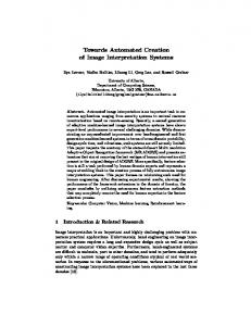
7. PERFORMANCE RESULTS We now describe performance results for the prototype implementation of our secure virtual networking framework. We obtained the throughput results using the NetIO network benchmark (version 1.23-2.1) and latency results using the ping tool. We used the NetIO network benchmark to measure the
Bridged
VLAN
EtherIP
Table 3: Round-trip Times using Ping. Minimum Average Maximum Mean Deviation Bridged 0.158 0.208 0.295 0.030 VLAN 0.171 0.233 0.577 0.049 EtherIP 0.174 0.239 0.583 0.052
140
Throughput (MB/sec)
120 100 80 60 40 20 0 1
2
4
8
Packet Size (kB)
(a) Tx Throughput Bridged
VLAN
EtherIP
140
Throughput (MB/sec)
120 100 80 60 40 20 0 1
2
4
8
Packet Size (kB)
(b) Rx Throughput Figure 7: NetIO Benchmark: Guest VM to Guest VM Throughput. network throughput for different packet sizes of the TCP protocol. We measured the Tx (outgoing) and Rx (incoming) throughput for traffic from one guest VM to another guest VM on the same physical host. For this purpose, we ran one instance of the benchmark on one guest VM as a server process and another instance on the second guest VM to do the actual benchmark. Figure 7 compares the throughput results for the standard Xen-bridged configuration (explained in Section 6) with configurations that include our VLAN tagging and EtherIP encapsulation extensions. The graphs show that the performance of our virtual networking extensions is comparable to that of the standard Xen (bridge) configuration. The VLAN tagging extension performs slightly better than the encapsulation extension for the Tx path, whereas the opposite happens in the case of the Rx path. The major cost in the Tx path for the EtherIP method is having to allocate a fresh socket buffer (skb) and copy the original buffer data into the fresh skb. When first allocating a skb, the Linux network stack allocates a fixed amount of headroom for the expected headers that will be added to the packet as it goes down the stack. Unfortunately, not enough space is allocated upfront to allow us to fit in the EtherIP header; so, we have to copy the data around, which is very costly. However, there is some spare headroom space, which is enough for the extra VLAN tag. As a result, the VLAN tagging method does not suffer from the packet copying overhead. The cost of copying data in the EtherIP case is greater than the cost of traversing two network devices (the physical Ethernet device and the Linux-provided VLAN device) for the VLAN packets. That is why the VLAN method is more efficient than the EtherIP approach for the Tx path.
In a future version of our prototype, we will add a simple fix to the kernel to ensure that the initial skbs have enough headroom upfront for the EtherIP header. In the Rx path, there is no packet-copying overhead for the EtherIP approach; the extra EtherIP header merely has to be removed before the packet is sent to a VM. In the VLAN case, the packets have to traverse two network devices (as in the Tx path) and the vSwitch kernel module. In the EtherIP case, the packets go straight from the physical device to the vSwitch kernel module. As a result of the extra step of traversing the VLAN device, the VLAN method performs slightly poorer than the EtherIP method for the Rx path. Our next prototype will avoid using the Linux VLAN code and have our vSwitch module do the tagging/untagging directly as in the EtherIP case. We expect this enhancement to bring the Rx throughput of the VLAN approach on par with that of the EtherIP approach. Table 3 shows the round-trip times between two guest VMs on a physical host for the bridged, VLAN, and EtherIP encapsulation cases obtained using the ping -c 100 host command, i.e., 100 packets sent. The average round-trip times for VLAN and EtherIP encapsulation are 12% and 14.9% higher than that of the standard Xen bridged configuration.
8. CONCLUSION In this paper, we introduced a secure virtual networking model and a framework for efficient and security-enhanced network virtualization. The key drivers of our framework design were the security and management objectives of virtualized data centers, which are meant to co-host IT infrastructures belonging to multiple departments of an organization or even multiple organizations. Our framework utilizes a combination of existing networking technologies (such as Ethernet encapsulation, VLAN tagging, and VPN) and security policy enforcement to concretely realize the abstraction of Trusted Virtual Domains, which can be thought of as security-enhanced variants of virtualized network zones. Policies are specified and enforced at the intra-TVD level (e.g., membership requirements) and inter-TVD level (e.g., information flow control). Observing that manual configuration of virtual networks is usually error-prone, our design is oriented towards automation. To orchestrate the TVD configuration and deployment process, we introduced management entities called TVD masters. Based on the capability models of the physical infrastructure that are given as input to them, the TVD masters coordinate the set-up and population of TVDs using a well-defined protocol. We described a Xen-based prototype that implements a subset of our secure network virtualization framework design. The performance of our virtual networking extensions is comparable to the standard Xen (bridge) configuration.
There are many avenues one can take to enhance both the networking and security aspects of this work. In the shortterm, we will enhance the prototype implementation with more auto-deployment elements, such as the TVD master and proxy. In the mid-term, we will investigate ways to enforce better separation between the various modules that deal with different TVDs on the same physical host. The goal is to provide stronger isolation among the various resources (such as TVD credentials) the modules have access to. One possible solution is to employ a dedicated VM per TVD on a given physical host for the management of the TVD elements on that host. Such a solution would certainly provide better isolation than our current implementation, in which all TVD proxies reside on the same VM (Dom0). A down-side of the solution is that it may require substantial data transfer between the various VMs belonging to a TVD and the management VM on the host. To deal with this issue, efficient inter-domain communication protocols need to be investigated. In the long term, we will fully automate the TVD deployment process, including key management. We will also investigate the use of emerging Trusted Computing technologies [22] for secure storage and handling of TVD credentials.
Acknowledgements We thank the other authors of [6] for valuable inputs. This work has been partially funded by the European Commission as part of the OpenTC project www.opentc.net.
9.
REFERENCES
[1] RFC 3378. EtherIP: Tunneling Ethernet Frames in IP Datagrams. [2] IEEE Standard 802.1Q-2003. Virtual Bridged Local Area Networks. Technical Report ISBN 0-7381-3662-X. [3] D. Andersen, H. Balakrishnan, F. Kaashoek, and R. Morris. Resilient Overlay Networks. In Proc. 18th ACM Symposium on Operating Systems Principles (SOSP-2001), pages 131–145, New York, NY, USA, 2001. ACM Press. [4] P. T. Barham, B. Dragovic, K. Fraser, S. Hand, T. L. Harris, A. Ho, R. Neugebauer, I. Pratt, and A. Warfield. Xen and the Art of Virtualization. In Proc. 19th ACM Symposium on Operating Systems Principles (SOSP-2003), pages 164–177, October 2003. [5] A. Bavier, M. Bowman, B. Chun, D. Culler, S. Karlin, L. Peterson, T. Roscoe, and M. Wawrzoniak. Operating Systems Support for Planetary-Scale Network Services. In Proc. 1st Symposium on Networked Systems Design and Implementation (NSDI’04), San Francisco, CA, USA, 2004. [6] A. Bussani, J. L. Griffin, B. Jansen, K. Julisch, G. Karjoth, H. Maruyama, M. Nakamura, R. Perez, M. Schunter, A. Tanner, L. van Doorn, E. V. Herreweghen, M. Waidner, and S. Yoshihama. Trusted Virtual Domains: Secure Foundation for Business and IT Services. Research Report RC 23792, IBM Research, November 2005. [7] A. T. Campbell, M. E. Kounavis, D. A. Villela, J. B. Vincente, H. G. De Meet, K. Miki, and K. S. Kalaichelvan. Spawning Networks. IEEE Network, 13(4):16–29, July-August 1999.
[8] A. T. Campbell, J. Vicente, and D. A. Villela. Managing Spawned Virtual Networks. In Proc. 1st International Working Conference on Active Networks (IWAN ’99), volume 1653, pages 249–261. Springer-Verlag, 1999. [9] C. I. Dalton. Xen Virtualization and Security. Technical report, HP Security Office Report, August 2005. [10] R. Davoli. VDE: Virtual Distributed Ethernet. In Proc. 1st International Conference on Testbeds and Research Infrastructures for the Development of Networks and Communities (Tridentcom 2005), pages 213–220. IEEE Press, February 2005. [11] S. W. Hunter, N. C. Strole, D. W. Cosby, and D. M. Green. BladeCenter Networking. IBM Journal of Research and Development, 49(6), 2005. [12] X. Jiang and D. Xu. VIOLIN: Virtual Internetworking on OverLay INfrastructure. In Parallel and Distributed Processing and Applications, volume 3358 of LNCS, pages 937–946. Springer-Verliag, Berlin, 2004. [13] M. E. Kounavis, A. T. Campbell, S. Chou, F. Modoux, J. Vicente, and H. Zhuang. The Genesis Kernel: A Programming System for Spawning Network Architectures. IEEE Journal on Selected Areas in Communications, 19(3):511–526, March 2001. [14] Common Criteria Project Sponsoring Organisations. Common Criteria for Information Technology Security Evaluation (version 2.0). May 1998, adopted by ISO/IEC as Draft International Standard DIS 15408 1-3. [15] L. Peterson, T. Anderson, D. Culler, and T. Roscoe. A Blueprint for Introducing Disruptive Technology into the Internet. SIGCOMM Comput. Commun. Rev., 33(1):59–64, 2003. [16] P. Ruth, X. Jiang, D. Xu, and S. Goasguen. Virtual Distributed Environments in a Shared Infrastructure. IEEE Computer, 38(5):63–69, May 2005. [17] P. Ruth, J. Rhee, D. Xu, R. Kennell, and S. Goasguen. Autonomic Live Adaptation of Virtual Computational Environments in a Multi-Domain Infrastructure. In Proc. IEEE International Conference on Autonomic Computing (ICAC-2006), June 2006. [18] A-R. Sadeghi and C. St¨ uble. Property-based Attestation for Computing Platforms: Caring about Properties, not Mechanisms. In Proc. 2004 Workshop on New Security Paradigms (NSPW-2004), pages 67–77, New York, NY, USA, 2005. ACM Press. [19] A. Sundararaj and P. Dinda. Towards Virtual Networks for Virtual Machine Grid Computing. In Proc. 3rd USENIX Conference on Virtual Machine Technology (VM 04), pp. 177-190, 2004. [20] J. Touch. Dynamic Internet Overlay Deployment and Management using the X-bone. Computer Networks, 36(2-3):117–135, 2001. [21] B. Traversat, A. Arora, M. Abdelaziz, M. Doigou, C. Haywood, J-C. Hugly, E. Pouyoul, and B. Yaeger. Project JXTA 2.0 Super-Peer Virtual Network, 2003. [22] Trusted Computing Group. TPM Main Specification v1.2, November 2003. https://www.trustedcomputinggroup.org.