Towards Direct Execution of Esterel Programs on Reactive Processors Partha S. Roop, Zoran Salcic, M.W. Sajeewa Dayaratne Department of Electrical and Computer Engineering University of Auckland, Auckland, New Zealand {p.roop,z.salcic}@auckland.ac.nz,
[email protected] ABSTRACT Esterel is a system-level language for the modelling, verification and synthesis of control dominated (reactive) embedded systems. Existing Esterel compilers generate intermediate C code that is subsequently mapped to a suitable target processor. The generated code emulates the reactive features of the language due to lack of support for these features on traditional processors. The resultant code is thus inefficient and bulky. Therefore, Esterel is not so effective for resource constrained embedded systems. This paper describes a reactive microcontroller called RePIC that has native support for reactive features of the language. Limited support for concurrent Esterel programs is demonstrated through a dual-processor RePIC architecture. A new benchmark suite for comparing the reactive performance of processors called the Auckland Reactive Benchmark (ARE-Bench) is used to demonstrate significant performance improvement and code compaction due to the proposed approach. This paper, thus, paves the way for resource constrained embedded system development using a subset of Esterel supported by RePIC like architectures.
1.
MOTIVATION AND BACKGROUND
Embedded systems are application specific digital systems that continuously interact with their immediate environment and react to external events (also called reactive systems). Esterel is a synchronous language, which is used for the specification [2], verification [3,4] and synthesis [3] of large reactive embedded applications such as aircraft flight controllers. Recently, Esterel is attracting a lot of attention from design automation community [13] due to its clan semantics that not only enables automatic design but also formal verification [3, 14] of safety-critical embedded applications. Esterel supports the modelling of delay, preemption, signal emission, synchronous communication, software interrupts and synchronous and asynchronous data handling.
Permission to make digital or hard copies of all or part of this work for personal or classroom use is granted without fee provided that copies are not made or distributed for profit or commercial advantage and that copies bear this notice and the full citation on the first page. To copy otherwise, to republish, to post on servers or to redistribute to lists, requires prior specific permission and/or a fee. EMSOFT’04, September 27–29, 2004, Pisa, Italy. Copyright 2004 ACM 1-58113-860-1/04/0009 ...$5.00.
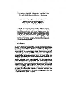
These features make Esterel an ideal choice for system-level modelling of reactive embedded applications. Some of these features are illustrated through the example of an ATM machine controller as shown in Figure 1. 1 2 3 4 5 6 7 8 9 10 11 12 13 14 15 16 17 18 19 20 21 22 23 24 25
loop emit insertCard; await cardInserted; abort abort emit enterPin; await pinEntered; await processingDelay; emit selectOption; await case withdrawdo await sumEntered; emit processTransaction; await transactionOK; emit releaseSum; emit printReceipt; case checkBalancedo emit processTransaction; await transactionOK; emit printReceipt; end await when incorrectPin; when invalidCard; emit ejectCard; end loop Figure 1: An ATM Controller in Esterel
Esterel, being a synchronous language, assumes a global synchronous clock that generates a tick event. An Esterel program samples its environment every tick to determine the status of signals and sensors and engages in a set of synchronous reactions. Any Esterel program is a collection of modules, each of which is a basic programming unit. Each module has an interface declaration part which declares the signals and sensors in the environment of the program. Signals carry pure control information and are either present or absent in a given tick. Following the interface declaration part is the body of the program. Being a reactive program, the body is an infinite loop that encloses the main behaviour of the ATM (line 1). Lines 2 and 3 model the emission of signal insertCard (for
one tick) and then delay until a card is inserted (using the await statement). While emit is instantaneous like a combinational logic block in hardware, await has at least one tick delay and is like sequential logic blocks. Lines 4 to 23 model the actual behaviour of a typical ATM. This behaviour has two parts: normal behaviour (lines 6 to 21) when a valid card is inserted and the associated PIN is correct or abnormal exception handling (line 23) when either an invalid card or incorrect PIN is detected. One approach to handle exceptions in Esterel is through the abort construct, which kills its body whenever a combination of signals (specified as abortion condition) is present in the environment. In the ATM example, the outer abort statement (line 4) kills its body (lines 5 to 21) when an invalidCard is entered. In this case, control jumps to line 23 directly. Abort incorporates preemption with static priority through nesting of aborts where outer aborts take precedence. In the ATM example, if both incorrectPIN and invalidCard are simultaneously present then the outer abort takes precedence. In addition to these features, Esterel supports the notion of synchronous broadcast communication among concurrent threads. Synchrony implies that an input and the corresponding output occur at the same time instant. Moreover, whenever any output is generated, it is synchronously broadcasted to all concurrent threads that may lead to a sequence of outputs all of which have the same time stamp. Conventionally, Esterel models of embedded systems are either synthesized as software running on a microcontroller [4-6, 13], hardware [7, 8] or a combination of the two using codesign as in POLIS [9]. Pure software implementation involves the generation of intermediate code (in C, for example) that is subsequently assembled to generate the desired machine code. Such mapping of Esterel to intermediate code is quite inefficient due to the requirement of indirectly simulating Esterel concurrency (through some form of scheduling), inefficient mapping of signals and sensors to ports on the microcontroller (through additional reaction code), indirect mapping of aborts and traps through interrupts and polling. Thus, the generated code has huge memory footprint, even for simple applications, rendering Esterel ineffective for small hand-held embedded devices. Direct compilation of Esterel to hardware obviously results in quite efficient realization supporting direct concurrency (unlike simulated concurrency in software). Pure hardware implementation, however, has some problems like loss of flexibility (new hardware needs to be synthesized for every Esterel program) and higher cost. Hardware-software solutions using codesign have been also proposed through the POLIS tools. POLIS, however, uses a conventional microcontroller (such as PIC[1] and HC11[16]) for code generation using the automata compilers. This has the same limitations of software compilers mentioned earlier. This paper proposes an intermediate approach by extending a commercial microcontroller (PIC [1]) to support direct execution of a subset of Esterel (so that the intermediate code generation step can be bypassed). This is achieved by incorporating architectural extensions to PIC so that Esterel can be executed directly on the new processor (RePIC, denoting Reactive PIC) preserving the semantics of a subset of the language. A dual-processor RePIC based architecture is also developed to demonstrate direct support for Esterel concurrency. Table 1 provides a qualitative comparison of
existing Esterel compilation techniques with the intermediate approach (hardware support for flexible software generation from Esterel) suggested here. Recently, a processor called REFLIX [10] has been proposed to provide hardware and instruction set support for mapping reactive embedded applications. REFLIX provides direct support for pure signals, preemption, signal emission and delay. It is demonstrated through a set of simple reactive programs that REFLIX performs much faster and generates more compact code compared to the original nonreactive core. REFLIX, however, has no support for direct execution of Esterel and does not preserve Esterel semantics. Hence, Esterel programs could not be mapped on to REFLIX directly. Moreover, REFLIX had no support for handling real concurrency. As REFLIX did not support Esterel semantics, only limited benchmarking comparison was done using simple reactive programs without any datahandling code. The main contributions described in this paper are as follows: 1. A new reactive microcontroller called RePIC is developed by extending a commercial microcontroller called PIC. RePIC supports direct execution of a subset of sequential Esterel code while preserving the synchronous model of execution. A dual-processor RePIC architecture is developed for the execution of concurrent Esterel programs while preserving synchronous broadcast and the logical tick. 2. In order to measure the reactivity (efficient reaction to external events) of processors, a new benchmark suite called the Auckland Reactive benchmarks (AREBench) is developed for evaluating the performance of processors. The ARE-Bench extends Estbench [11, 12] (which was developed for the performance evaluation of Esterel compilers) for the performance evaluation of reactive processors. 3. Benchmarking comparisons using ARE-Bench demonstrate that the proposed approach is superior in terms of code size and execution time when compared to major Esterel compilers. The huge compaction of the resulting code suggests possible use of Esterel to develop resource constrained embedded devices in the future. The rest of the paper is organized as follows: Section 2 presents the architectural extensions to PIC. Section 3 presents how the proposed extensions preserve Esterel semantics. Section 4 discusses some of the implementation results and Section 5 presents the new benchmark, AREBench, and the results of benchmarking. The sixth and final section is devoted to concluding remarks.
2. 2.1
ARCHITECTURAL EXTENSIONS FOR REACTIVITY Features of the RePIC Core
The RePIC design is obtained by extending PIC while preserving all its original features. RePICs external interface and datapath are shown in Figures 2 and 3 respectively. In order to accommodate the new reactive instructions, the original PICs instruction length has been extended by one bit. Other key extensions required to facilitate reactive applications are summarized as follows:
Table 1: Qualitative comparison of Esterel compilation techniques Esterel Compilation Hardware implementation (A)
Advantages
Disadvantages 1. Higher cost.
1. Reactive behaviours mapped onto FSMs.
2. Loss of flexibility (each Esterel program and any modification requires resynthesis).
2. Small footprint and cheap implementation.
Software Implementation (B)
3. More difficult to map the C programs used in data handling.
3. Supports real concurrency. 1.Lower cost.
1. Large footprint (memory requirement).
3. More flexible (same microcontroller can run any Esterel program).
2. Scheduling overhead for simulation of concurrency.
4. Easy mapping of data-handling code.
3. Overhead for mapping of signals and sensors. 4. Complex compilation process. 5. Overhead for abort translation. 6. Overhead for priority resolution. 7. Emulates parallelisms by serialization of concurrent activities.
RePIC and Direct Code Generation (C)
1. Same cost as software (B).
1.Lower efficiency compared to hardware.
2. No overhead for signal mapping.
2. Complex approach to concurrency support compared to direct hardware.
3. No overhead for abort. 4. No overhead for priority resolution. 5. Fast reaction and response times compared to software. 6. Very compact code compared to software. 7. Higher flexibility compared to hardware. 8. Limited concurrency support through dual-processor architecture.
1. Introduction of four user-programmable internal timers to generate four single-bit internal input signals upon timer overflows.
progdata[14:0]
progadr[12:0] ramtout[7:0]
ramdtin[7:0]
2. Four I/O ports have been added (SIGINA, SIGINB, SIGOUTA and SIGOUTB) to provide a total of sixteen single-bit input signal lines (in which 12 are external input signals and the other 4 are the internal timer-generated signals) and twelve single-bit external output signal lines. These signal lines enable direct mapping of Esterel pure signals to RePIC.
RePIC Core
porta_in[4:0] portb_in[7:0]
ramadr[8:0] readram writeram porta_out[4..0]
rbpu signal_inA[7:0]
Note:
signal_inB[3:0]
Program ROM Data Bus / Address Bus
Int[3:0]
Data RAM Data Bus / Address Bus/ Control Signals
porta_dir[4..0] portb_out[7..0] portb_dir[7..0]
3. ABORT mechanism is introduced to handle Esterel aborts and traps. This mechanism can replace standard interrupts when fast preemption is vital and there is no requirement to return to the exact context.
signal_outB[3..0] ponrst_n mclr_n
4. Other new instructions, including EMIT, SUSTAIN, PRESENT, TAWAIT, SAWAIT and CAWAIT are added to support other Esterel-like reactive instructions (Section 2.2).
signal_outA[7..0]
clkin
I/O Ports powerdown
PORT-B Interrupt Inputs CPU Reset / Clock / Stop or Start Indicators
startclkin clkout
5. Emission of multiple signals within a single instruction cycle is supported in order to support the instantaneity principle of Esterel.
Figure 2: External View of RePIC
6. Introduction of a logical tick in RePIC to preserve the predefined tick event in Esterel(Section 3.1).
This is a prototype implementation and customizable implementation of RePIC for a given Esterel program is easy. The core has been fully described in VHDL with the use of generics (parameters) to enable direct customisation to the requirements of the program that will run on the processor.
7. A dual-processor architecture is developed to demonstrate support for concurrent Esterel programs.
2.2
Instruction Set Architecture for RePIC
RePIC contains 7 new Esterel-like reactive instructions: EMIT, SUSTAIN, TAWAIT, SAWAIT, CAWAIT, PRESENT and ABORT.A more detailed description of each of them is pre-
sented in Table 2. Most of the new reactive instructions are implemented as a single-word instruction, CAWAIT, PRESENT and ABORT, however, require two words for immediate operand or address information. ABORT, which is introduced to support preemption, is the most important among all the new instructions. Its implementation follows one of REFLIX [10]. Up to four priorities of nesting of ABORTs are allowed in the current design. Following the semantics of Esterel aborts, the outermost ABORT will always have the highest priority while the innermost one has the lowest. ABORT in RePIC can currently work with up to twelve external and four internal timer-generated signals. The Abort Handling Block (AHB in Figure 3) is a dedicated hardware implemented to control the activation, operation and termination of ABORTs in RePIC. An implementation of the ATM example presented in Figure 1 in RePIC assembly language is shown below. Figure 3: RePIC’s Data Path for ABORT Handling 1 2 3 4 5 6 7 8 9 10 11 12 13 14 15 16 17 18 19 20 21 22 23 24 25
loop: EMIT insertCard SAWAIT cardInserted %Load Abort Address and initiate abort LDAADDR L0 ABORT invalidCard %Load Abort Address and initiate abort LDAADDR L1 ABORT incorrectPin EMIT enterPin SAWAIT pinEntered EMIT selectOption LDCADDR L1 CAWAIT withdraw, checkBalance SAWAIT sumEntered EMIT processTransaction SAWAIT transactionOK EMIT releaseSum, printReceipt GOTO L0 L1: EMIT processTransaction SAWAIT transactionOK EMIT printReceipt L0: EMIT ejectCard GOTO loop
It can be seen that the assembly code resembles the original Esterel code. Two instructions are needed to implement the abort mechanism (line 5,6 and 8,9) LDAADDR [addr] and ABORT [signal]. The former is used to specify the continuation address of the abort (the address of the next instruction to execute if the body is aborted) while the latter specifies the signal which the abort is sensitive to. No context switching occurs when an abort is taken and there is no need to write a separate interrupt service routines. Such a mechanism allows Esterel abort statements to be easily converted to the equivalent RePIC machine code. Also worth noting is the ability to emit multiple signals in the same instruction(line 18).
3.
OPERATIONAL SEMANTICS OF ESTEREL IN REPIC
This section presents an operational approach for preserving Esterel semantics on a set of reactive processors. Initially, execution of sequential programs on a single RePIC is discussed. Subsequently, a dual-processor RePIC architecture is presented and Esterel execution on this platform is discussed. The Esterel subset handled in RePIC does not include: 1. Detection of concurrent signal presence (using PRESENT condition) in a concurrent thread when that signal is generated in another thread. 2. Support for immediate awaits. 3. Support for valued signals of arbitrary types (only integer type is supported). We also assume that the Esterel programs to be executed on RePIC are free of causal cycles.
3.1
Preserving the Synchrony Hypothesis
The synchronous model implies that reactions to input signals are instantaneous and occur at discrete logical instants called ticks. As a result, a sequence of actions may need to be performed within the duration of a single tick. In order to model the logical tick of Esterel in RePIC, a tick with variable length in terms of absolute time is implemented. The duration of one tick is determined by the time required to execute all the instantaneous instructions that are placed between any two consecutive await (i.e. TAWAIT, SAWAIT or CAWAIT) or halt instructions which are the tick delimiting instructions. Whenever one such instruction appears, the current tick is said to have elapsed and a new tick starts. A local tick counter is used to keep track of the completion of each logical tick. The tick counter is also used for correct implementation of strong and weak aborts.In case of
Table 2: New RePIC Instructions for Supporting Reactivity Esterel Feature
Assembly Syntax
RePIC Instruction(s)
Length Description 15-bit word 1 Signal(s) is/are set high for one tick.
Signal Emission
EMIT signal(s)
Signal Sustenance
SUSTAIN signal(s) SUSTAIN signal(s)
1
Signal(s) is/are set high forever.
Delay
TAWAIT delay
TAWAIT delay
1
Signal Polling
SAWAIT signal
SAWAIT signal
1
Wait until delay (number of instruction cycles) elapses. Wait until signal occurs in the environment
LDCADDR address
2
CAWAIT signa11 , signal2 BTFSS register , bit
2
Conditional Signal CAWAIT signal1 , Polling signal2, address
Signal Presence
PRESENT signal , address
EMIT signal(s)
Wait until either signal1 or signal2 occurs. If signal1 occurs, execute instruction at the address immediately followed, or else at the specified address . Instruction at the address immediately followed will be executed if signal is present, or else at the specified address
GOTO address Preemption
ABORT signal , address
LDAADDR address
2
Program finishes its current tick and jumps to address in the occurrence of signal
ABORT signal
strong abort, the body doesn’t get control in the abortion instant unlike a weak abort. The Esterel to RePIC code generator also reorders some of the Esterel instructions during its pre-processing stage. This is done to ensure that trivial read/write dependencies are resolved. For example observe the code below. emit a present d then emit c; present b then emit d; emit b According to Esterel semantics all of a,b,c and d should be emitted to the environmentits. To ensure this while executing sequentially on RePIC, the Esterel to RePIC preprocessor reorders the instructions as shown below.
RePIC Assembly: EMIT A BTFSS S GOTO L0 EMIT B L0: TAWAIT TICK EMIT C
Esterel Code emit a; present S then emit b end pause; emit c
EMIT A
BTFSS S
GOTO
EMIT B
TAWAIT 1
EMIT C
PRESENT S
Signal A
emit a emit b present b then emit d; present d then emit c;
Signal B
Signal C
Signal S
Tick 1
3.2
Example of synchronous execution
All Esterel output signals are emitted instantaneously and last for one logical instant (till the start of the next tick). Similarly, signals in RePIC will be set high after an EMIT instruction is executed and will be cleared when the next tick delimiting instruction is decoded. In this sense, the instantaneity of signal broadcasting within a logical tick is preserved in RePIC through the introduction of a variable tick depending on how frequent the await instructions occur in the program. Figure 4 shows how signals A and B are emitted at different instances as soon as they are decoded and executed in real time. Although signal A is emitted slightly earlier than signal B, as they both belong to the same tick, they are cleared together when the first tick elapses. The second tick is consumed by the TAWAIT instruction followed by the emission of signal C. Note that signal S is present in all ticks (has been set high).
3.3
Tick 2
Example of SUSTAIN and ABORT
Figure 4: Implementation of Esterel Tick in RePIC
SUSTAIN instruction causes the specified signal(s) to remain high for the lifetime of either an ABORT body or the entire program depending on where the instruction is placed within the program. The former case occurs when the SUSTAIN instruction is located within an ABORT body and the specified signal(s) will automatically be cleared when the ABORT is preempted. The latter case happens if the SUSTAIN instruction is outside an ABORT body. Figure 5 depicts the execution of a SUSTAIN instruction within an ABORT body (a weak abort construct in Esterel). For the first two ticks S in not high and hence A is sustained. In the third tick when S occurs abortion happens while the body gets a chance to execute one last time, leading to the emission of both A and B.
Esterel
RePIC Assembly:
weak abort sustain A when S emit B
LDAADDR L0 ABORT S SUSTAIN A L0: EMIT B;
Instruction Cycle
Sustain A
Sustain A
Sustain A
EMIT B
threads are merged). This design is an initial prototype and work is in progress to develop a scalable multiprocessor architecture using RePIC cores.
4.
IMPLEMENTATION
The VHDL model for the PIC processor[1] was extended to create the Reactive PIC (RePIC) VHDL model. Both cores were synthesized using Alteras Quartus II version 2.2. The target FPGA used for synthesis was the EP20K200EFC4842 which is a member of the APEX20KE family. the results of synthesis are presented in Table 3. Due to additional logic components in the data path for reactivity support, the modified RePIC system consumes nearly double the logic resources than the non-reactive PIC[1] processor.
Signal A
Table 3: Sythesis results for RePIC and PIC
Signal B
Signal S Tick 1
Tick 2
Tick 3
Figure 5: Implementation of Signal Sustenance in RePIC
3.4
Dual-processor architecture
In order to demonstrate real concurrency and synchronous broadcast, a dual processor RePIC architecture, as shown in Figure 6, was developed for handling Esterel programs with two parallel threads. Since valid Esterel programs have no data dependency, the two processors concurrently access and execute their respective threads from a shared memory, implemented as a cycle shared memory, within the same machine cycle. Synchronisation among local ticks of threads and the global system tick is managed using global and local tick counters. Global tick counter determines when the next tick starts in the global system and also ensures that signals are prolonged until the global tick elapses. AWAITS are also synchronised with global ticks.
Microprocessor System (i.e. Core + Data RAM + Program ROM) Number Used Logic Elements Total Available Percentage Used Maximum operating frequency
5.
PIC 1082 8320 13% 45.83Mz
RePIC 2068 8320 24% 40.27Mhz
BENCHMARKING
All benchmarks used were based on the subset of Esterel supported by RePIC. These benchmarks were compiled for RePIC as well as the other architectures mentioned in this section. Benchmarking results may be summarized as follows: • A significant reduction in code size was achieved on RePIC compared to PIC. Code size comparisons were done for both manually translated code as well as those compiled using various Esterel compilers. • A significant improvement in execution time was also achieved for both manually translated code as well as those translated using the Esterel compilers. • A significant advantage over some other microprocessors in terms of code size was also noticed.
5.1
ARE-Bench A New Benchmark Suite
Figure 6: Implementation of synchronous broadcast
In [10] a set of pure reactive applications were developed to analyse the performance of processors while executing reactive tasks. These benchmarks ignored the fact that reactive programs are normally a combination of data dominated and control dominated parts. Edwards developed Estbench [11,12] to compare the performance of Esterel compilers. Estbench contained many real Esterel programs with combination of data dominated and control dominated parts. However, we felt a need to create a benchmark suite to compare the reactive performance of processors due to the following reasons.
Using this architecture, two threaded Esterel programs may be executed efficiently. In case of more then two threads, automata style compilation is employed to convert programs with more than two threads to two threaded programs (small
• Reactive performance depends on the efficiency of preemption and priority resolution. In order to measure these effectively, varying levels of nesting of aborts and priorities were encoded in our benchmarks.
• Different combinations of programs ranging from pure reactive to mostly data dominated and a combination of data and control-oriented behaviours were created to evaluate the performance of processors. ARE-Bench combines benchmarks from Estbench [12], [10] and the Polis distribution [9] where the programs have been customised appropriately to enable objective comparison of reactivity.
Table 4: Code size comparison in words for pure reactive benchmarks and manual code generation Application ATM Elevator Pump Controller
RePIC 22 23
PIC 74 70
8051 102 45
68HC11 163 79
NIOS-16 219 116
15
50
35
56
80
Startup Benchmark
24
64
48
76
94
TCP Receive TCP Transmit Traffic Light Average
7 10 18 17
27 29 71 55
28 20 70 50
18 31 114 77
41 46 147 106
Table 5: Execution time comparison PIC vs RePIC using manual code generation Application ATM Elevator Pump Controller Startup Benchmark TCP Receiver TCP Transmitter Traffic Light Average
5.2
Execution Time (us) RePIC PIC 2.68 8.73 2.38 5.85 1.99 5.76 3.97 7.33 0.7 2.36 1 2.53 2.28 7.51 2.78 6.74
Total Speed Up 3.26 2.4 2.89 1.85 3.37 2.53 3.29 2.7
The Benchmarking Process
The benchmarking process was divided into two separate parts: 1. Subsets of applications from ARE-Bench were manually translated into the machine code of a number of microprocessors. The selected benchmarks were small purely reactive applications, since manual translation of larger benchmarks is a very tedious process. Both the execution time and the code size were compared. 2. A subset of larger applications was compiled using standard Esterel compilers to produce first C code and then the commercial PIC compiler and assembler were used to produce PIC machine code. For Esterel to RePIC code generation a simple RePIC code generator was developed and used. These two contrasting approaches were used to highlight the inefficiencies of typical code generators and also to highlight that manual code generation, though more direct and efficient, is only possible for toy programs and compilers have to be used for real programs.
Table 6: Code size comparison between various compilers Benchmark ATDS-100 Driver Elevator Filter LONG_ACC_CAL LONG_ACC_DER PumpController Runner SpeedSense Startup TCPReceive TCPTransmit TrafficLight VER_ACC_CAL VER_ACC_DIAG
5.2.1
Maximum Nesting of Aborts
Colombia Esterel Compiler 0.3
0 0 0 0 0 0 2 0 0 1 0 0 2 0 0
11289 510 378 109 101 225 692 594 193 140 301 681 107 260 260
REPIC Esterel Esterel Compiler Esterel Compiler Compiler (Single/Dual Studio 4.0 V3 V5 Processor) 17827 19735 5816 282 1540 1588 1575 68 1147 1192 474 23 308 303 231 9 504 518 366 25 554 578 431 32 811 945 346 15 979 1035 500 23 493 501 352 22 869 1143 305 24 498 499 293 7 588 593 260 10 1008 1188 373 18 306 301 229 9 675 661 522 28
Comparison using manual translation of Esterel
The first comparison was done by translating some of the purely reactive benchmarks from ARE- Bench to the native code of RePIC, PIC [1], Motorola 68HC11 [16], Intel 8051 [17] and 16-bit NiOS [18]. Table 4 summarizes these results and shows a clear advantage of RePIC in terms of code size. Though generating code by hand significantly reduces any overhead incurred by compilers, we can still see a significant reduction in code size for RePIC. This is mainly due to the native support for Esterel in RePIC. This is evident since benchmarks having a higher number of nested aborts (ATM and Traffic Light) result in the greatest reduction in code size. On an average, the original PIC processor requires three times larger memory to store the same program functionality than RePIC. The execution time of original PIC and RePIC was also compared (as shown in Table 5). On an average, a speedup of 2.7 was achieved. However, applications that contain many levels of nested aborts (ATM and Traffic Light) show a speed up of approximately 3.2.
5.2.2
Comparison using Esterel compilers
a) Code size comparison A comparison was done between the code generated by traditional Esterel compilers and code produced for RePIC (by using the RePIC code generator). Out of the 44 AREBench programs a subset used in the comparison is shown in Tables 6 and 7. The performance of four Esterel compilers was compared with the direct code generation of the RePIC compiler. The selected compilers were, Colombia Esterel Compiler V0.3[18], Esterel Studio V4.0 by Esterel technologies [8], the Esterel V5 compiler [3] and the automata based Esterel V3 compiler[3]. The Colombia Esterel Compiler performed best among all Esterel compilers though direct machine code generated by RePIC was much more compact. The Esterel V3 compiler performed well for single threaded programs but its performance degraded drastically as the number of threads grew. A summary of the results are shown in Table 6 which shows that that the percentage reduction in code size using various compilers in the high nineties compared to the 76% reduction achieved using manual translation. Since traditional architectures have no notion of Esterel tick, extra software support is needed to ensure that signals
Table 7: Execution time (us) for various compilers Benchmark ATDS-100 Driver Elevator Filter LONG_ACC_CAL LONG_ACC_DER PumpController Runner SpeedSense Startup TCPReceive TCPTransmit TrafficLight VER_ACC_CAL VER_ACC_DIAG
Maximum Nesting of Aborts
Colombia Esterel Compiler 0.3
0 0 0 0 0 0 2 0 0 1 0 0 2 0 0
1250.92 57.79 46.79 11.79 11.09 25.75 78.48 67.83 22.09 16.24 33.79 77.87 11.61 28.63 28.63
REPIC Esterel Esterel Compiler Esterel Compiler Compiler (Single/Dual Studio 4.0 V3 V5 Processor) 2361.63 2576.57 875.09 68.12 191.36 195.99 220.95 15.29 147.01 152.69 59.8 2.38 37.27 36.84 26.53 1.59 61.93 63.21 43.73 4.67 68.18 70.19 53.6 6.16 105.19 122.22 45.83 1.99 125.1 131.91 64.86 3.77 61.11 61.9 43.12 4.07 114.45 149.81 38.15 3.97 63.55 63.99 37.62 0.7 74.99 75.78 30.81 1 132.34 154.87 51.33 2.28 37.1 36.67 26.36 1.59 82.93 81.63 63.55 6.06
are emitted and polled for correct time durations. Furthermore, instruction- scheduling overhead is also introduced when converting multiple concurrent Esterel code segments into C code (using the suspend-resume approach [8] or the fork-join approach [18]). The conversion of Esterel abort statement also leads to a significant increase in code size. An interrupt service routine needs to be implemented for each signal that causes preemption. Moreover, each interrupt has an overhead involved in initialization. Although the handling of abort priorities is done using hardware in RePIC, PIC code needs to be generated to handle this in software. b) Execution time comparison Since the execution can take any one of many different execution paths (i.e. paths in the underlying finite state machine), calculations were based on the assumption that each benchmark executes each state of the underlying finite state machine only once. This is a fair assumption since we are only interested in the speed up achieved by the proposed approach. Table 7 gives a summary of the timing data that was obtained for some of the benchmarks. The average speed up was 28.96. c) Summary It is evident that regardless of the Esterel compiler used, the execution time on RePIC is significantly shorter than that for PIC. The average speed up was approximately 28.96, although for some benchmarks RePIC was almost 100 times as fast as PIC. These results show that by providing an appropriate framework for directly compiling Esterel models into machine code, the proposed approach not only reduces the code size considerably but also obtains a significant speed up compared to traditional methods. In summary, in comparison to PIC and other microcontrollers, RePIC achieves an average speed up of 2.7 and an average a reduction in code size of 76% for applications that are manually translated to both PIC and RePIC. Much higher improvements were achieved when comparisons were done using traditional compilation methods. When compared to conventional Esterel compilers, the RePIC compiler produced code that was on an average 97% more compact. One major reason for such huge speedup compared to efficient Esterel compilers like CEC[7] is that unlike these compilers, we only handle a subset of Esterel where complicated
constructs of Esterel such as checking for signals emitted by concurrent threads using Esterel’s present constructs are not handled. We are currently developing a synchronous multiprocessor architecture to handle full Esterel.
6.
CONCLUSIONS
This paper presents a new approach for the support of Esterel execution on a microprocessor while preserving most of the semantics of the language. Existing compilers for a concurrent and reactive language like Esterel, first compile programs to an intermediate high-level language, which is then compiled and executed on a conventional sequential processor. Typically the resulting code is both bulky and inefficient. As a result, Esterel is rarely used in the design of resource constrained embedded systems. Our approach remedies these shortcomings by proposing a new reactive microcontroller (RePIC) that supports features of Esterel and enables the direct conversion of Esterel into the machine code of the microcontroller. In order to study the efficacy of the approach, a new benchmark suite (AREBench) has been proposed for comparing the performance of reactive applications running on different microprocessors. Benchmarking results reveal significant improvement in performance, in terms of execution time and code size, when using RePIC. Though RePIC design shows an alternative approach to Esterel execution, work is in progress to overcome some shortcomings. Currently the dual processor architecture is limited in only being able to execute Esterel programs with two concurrent threads (or use automata compilers to compact small threads to create a two threaded program). Work is in progress to develop a real multiple processor architecture based on RePIC that will allow execution of Esterel programs with arbitrary number of concurrent threads while preserving the semantics of the Esterel language. Moreover, we have handled a subset of Esterel in this paper. A possible use of efficient static analysis (conventional compilation) supported by reactive processors is an interesting area of research for the future.
7.
ACKNOWLEDGMENTS
The authors acknowledge an initial prototype implementation of RePIC core by two year-4 undergraduate students, C. M. E. Chow and J. S. Y. Tong, (Department of Electrical and Computer Engineering, University of Auckland, New Zealand)
8.
REFERENCES
[1] Microchip.Ltd, (1998 - Last Updated) “PIC16F8X Datasheet” [Online]. Available http://www.microchip.com/download/lit/pline/picmicro/families/ 16f8x/30430c.pdf [Last Accessed 10/04/2003] [2] F. Boussinot and R. de Simone, “The ESTEREL language,” Proceedings of the IEEE, vol. 79, pp. 1293-1304, 1991. [3] G. Berry and G. Gonthier, “The Esterel Synchronous Programming Language: Design, Semantics, Implementation,” Science of Computer Programming, vol. 19, pp. 87-152, 1992. [4] M. Chiodo, P. Guisto, A. Jurecska, L. Lavagno, H. Hsieh, K. Suzuki, A. L. Sangiovanni- Vincentelli, and E. Sentovich, “Synthesis of Software Programs for Embedded Control Applications,” presented at 32nd Design Automation Conference, San Francisco, CA, 1995.
[5] F. Balarin and M. Chiodo, “Software synthesis for complex reactive embedded systems,” presented at Computer Design, 1999. (ICCD ’99) International Conference on, 1999. [6] Leupers, “Code generation for embedded processors,” presented at System Synthesis, 2000. Proceedings. The 13th International Symposium on, 2000. [7] S.A. Edwards, (1/9/2003 - Last Updated) “CEC: The Colombia Esterel Compiler” [Online]. Available http://www1.cs.columbia.edu/ sedwards/cec/ [Last Accessed 10/10/2003] [8] Esterel-Technologies (2003 - Last Updated) “Esterel Technologies Website” [Online]. Available http://www.esterel-technologies.com [Last Accessed 11/11/2003] [9] M. Chiodo, P. Giusto, H. Hsieh, A. Jurecska, L. Lavagno, C. Passerone, A. Sangiovanni- Vincentelli, E. Sentovich, K. Suzuki, and B. Tabbara, Hardware-Software Co-Design of Embedded Systems: The Polis Approach. New York: Kluwer Academic Publishers, 1997. [10] Z. Salcic, P. S. Roop, M. Biglari-Abhari, A. Bigdeli, “REFLIX: A Processor Core with Native Support for Control Dominated Embedded Applications”, Elsevier Journal of Microprocessors and Microsystems, Vol. 28, pp. 13-25, 2004 [11] S.A. Edwards, “An Esterel compiler for large control-dominated systems,” Computer-Aided Design of Integrated Circuits and Systems, IEEE Transactions on, vol. 21, pp. 169-183, 2002. [12] S.A. Edwards, (2003 - Last Updated) “The Estbench Esterel Benchmark Suite” [Online]. Available http://www1.cs.columbia.edu/ sedwards/software.html [Last Accessed 17/11/2003]. [13] S. A. Edwards, “Compiling Esterel into Sequential Code”, Design Automation Conference (DAC) 2000. [14] Ramesh S. and Bhaduri P. “Validation of pipelined processor designs using Esterel tools”, Proceedings of the 11th International Conference on Computer Aided Verification, Springer Verlag, 1999, pp. 84 - 95. [15] Caspi P, Girault, A, Pilaud, D. “Automatic distribution of reactive systems for asynchronous networks of processors”, IEEE Transactions on Software Engineering, Vol.25, Iss.3, May/Jun 1999 pages:416-427 [16] Spasov, Microcontroller Technology: The 68HC11: Prentice Hall, 1999. [17] Schutti, M. Pfaff, and R. Hagelauer, “VHDL design of embedded processor cores: the industry- standard microcontroller 8051 and 68HC11,” presented at ASIC Conference 1998. Proceedings. Eleventh Annual IEEE International, 1998. [18] (2003 - Last Updated) “NIOS Embedded Processor: 16-bit Programmers Reference Manual” [Online]. Available http://www.altera.com [Last Accessed 17/11/2003] [19] (2004 - Last Updated) “The Colombia Esterel Compiler [Online] Available http://www1.cs.columbia.edu/ sedwards/cec/ [Last Accessed 20/03/2004]