Towards Dynamic Planning and Guidance of. Minimally Invasive Robotic Cardiac Bypass Surgical. Procedures. G Lehmann, A Chiu, D Gobbi, Y Starreveld, ...
Towards Dynamic Planning and Guidance of Minimally Invasive Robotic Cardiac Bypass Surgical Procedures G Lehmann, A Chiu, D Gobbi, Y Starreveld, D Boyd, M Drangova, T Peters The John P Robarts Resesrch Institute, The University of Western Ontario and the London Health Sciences Centre. London Ontario, Canada
Abstract. Conventional open-heart coronary bypass surgery requires a 30-cm long incision through the breast-bone and stopping the beating heart, which inflict great pain, trauma and lengthy recovery time to patients. Recently, a robot-assisted minimally invasive surgical technique has been introduced to coronary bypass to minimize incisions and avoid cardiac arrest in order to eliminate the medical complications associated with open-heart surgery. Despite its initial success, this innovation has its own limitations and problems. This paper discusses these limitations and proposes a framework that incorporates image-guidance techniques into MIRCAB surgery. We present two aspects of our preliminary work; 1) A Virtual Cardiac Surgical Planning system developed to visualize and manipulate simulated robotic surgical tools within the virtual patient. 2) Our work towards the extension of the static planning system to a dynamic situation that would model the position, orientation and dynamics of the heart, relative to the chest wall, during surgery.
1.1 Background Traditional coronary artery bypass procedures (CAB) involve the utilization of a blood vessel (bypass graft) from another part of the body and surgically creating an alternate blood supply route, bypassing the blocked part of the artery. Minimally invasive direct coronary artery bypass (MIDCAB) techniques eliminate the need for full sternotomy and cardio-pulmonary bypass (CPB), and are all performed on the beating heart through a small incision in the chest wall. When employed in conjunction with a heart stabilizer, MIDCAB procedures eliminate many of the complications caused by CPB [1;2]. Despite its initial success, MIDCAB has some apparent shortcomings. Due to the small incision, access to the target vessels is limited and the execution of the anastomosis is more challenging. As a result of limited visualization and heart motion, the anastomosis may be less precise [3]. More recently, endoscopic port-access techniques have been incorporated into MIDCAB allowing minimally-invasive procedures to be employed. Nevertheless, a major limitation of these approaches is that the long-handled instruments used in MIDCAB magnify hand tremors, which can make precise suturing difficult and tiring. In addition, the surgeons’ natural motion is actually the reverse of the motions of the instruments due to the fact that the instruments pass through a “key hole”. W. Niessen and M. Viergever (Eds.): MICCAI 2001, LNCS 2208, pp. 368-375, 2001. Springer-Verlag Berlin Heidelberg 2001
Minimally Invasive Robotic Cardiac Bypass Surgical Procedures
369
Robot-assisted telesurgical systems were developed to avoid the restrictions of conventional endoscopic port-access instruments, to remove surgeon tremor, provide a minification factor between the operator’s movements and the tools, and permit the surgeon to perform the procedure from a comfortable position. Currently, two telesurgical robotic systems have been used experimentally and clinically (www.intuitivesurgical.com, www.computermotion.com). Over the past few years, the results of minimally invasive robotic coronary artery bypass (MIRCAB) procedures for closed-chest CPB have been encouraging [4-6]. MIRCAB nevertheless has several technical limitations, including the lack of guidance from conventional 2-D images of patients, possible improper port placement and limited field of view of the operative site from the endoscope. These problems must be overcome to further reduce trauma and risk to patients, which would in turn lead to shorter hospital stays and lower health care expenses.
1.2 A Virtual Environment for Surgical Planning We believe that a virtual representation of the surgical environment will become an integral part of surgical planning and guidance for minimally invasive robot assisted therapies. Through the use of such simulation, the surgeons can familiarize themselves with new robotic technologies, optimize instrument placement, and plan patient specific procedures. Such virtual planning environments have been proposed by us and others [7,8] that allow the surgeon to simulate and validate incision sites. Ultimately the goal of this research is to provide the surgeon with a dynamic virtual representation of the patient’s thorax in the operating room where the patient’s heart motion and positioning are synchronized in the virtual environment. With such a system, the surgeon would always maintain a global view of the operative site, and not be constrained by the small field-of-view of the endoscope.
1.3
Preliminary Work
In this paper we report two aspects of both our preliminary work aimed at providing a virtual cardiac surgical planning environment (VCSP) workstation to plan port placements for MIRCAB, as well as our work to position and animate a virtual heart model within the virtual representation of the patient’s thorax. By presenting the VCSP and the virtual heart model together in one paper we hope to give an overview of our preliminary work towards creating a virtual environment for surgical planning of robot assisted coronary by-pass surgery.
2. Cardiac Surgical Planning Platform The Virtual Cardiac Surgical Planning platform (VCSP) [8] is based on the infrastructure that was developed for the Atamai Surgical Planner (ASP) (www.atamai.com). ASP is written in C++ as well as Python (www.python.org), and
370
G. Lehmann et al.
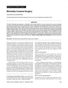
relies heavily on the Visualization Tool Kit (VTK) (www.kitware.com) library of C++ classes. A typical computer configuration employed to run the surgical planning platforms is a Pentium III 650 MHz, 256MB RAM, and a 16MB video card with hardware 3-D acceleration. The capabilities of VCSP are as follows: Integration of dynamic (ECG-gated) surface and volume-rendered images • derived from CT and/or MRI Visualization and manipulation of surface models of heart and thorax • Interactive modeling of the robotic arms and the endoscope • Interactive distance and angle measurement (3D Ruler) • Generation of virtual endoscopic images from arbitrary viewpoints • Interactive zoom of the modeled environment • Displacement and rotation of individual objects, • Transparency of overlying structures to expose the target for planning thoracic • port placement. For a bypass operation, the structures that are of most concern to the surgeons are the bypass graft, the coronaries, heart, ribs and the chest wall. The internal thoracic arteries, left coronary artery and the heart are extracted from the MRI images, while the ribs and the chest wall are obtained from the CT images. Segmentation is performed semi-automatically using thresholding and 3-D region-growing [9]. Within this environment, an operator may examine the topology of the patient’s thoracic cavity and manipulate simulated surgical tools and endoscope to determine the proper port placement to ensure that they can access the targeted operative site. 2.1 Determination of Port Configuration It is particularly important to be able to position the inter-costal ports relative to the surgical target(s) such that the surgical tools and endoscopes may interact together without collision. Tabaie et al.[10] describe a “magic pyramid” configuration that establishes the optimum configuration of the ports. Using VSCP, an operator can manipulate simulated tools (Fig 1) within the virtual thoracic cavity to determine a workable port configuration. The following steps are used to find the parameters of the pyramid: 1. Examine the topology of the patient through the 3-D thorax model of the patient. Decrease the opacity of the skin to reveal ribs and target. 2. Insert the virtual endoscope. Locate the target via the simulated endoscopic view. 3. Insert left and right thoracic ports. Perform a visual check to ensure the ports do not collide with each other or any of the thoracic structures. 4. Add the simulated trochars to approach the target and make measurements of the “magic pyramid” parameters by using the user interface built into the measurement windows. At least three fiducial markers must be placed on the surface of the chest for preoperative image acquisition and kept in place until the operation. The pre-operative 3-D model to the patient is registered to the model during the procedure using a freehand tracking system. After the patient and model are in registration, the predetermined incision points can be reproduced on the actual patient. The distances
Minimally Invasive Robotic Cardiac Bypass Surgical Procedures
371
from each incision point to all the markers can be measured by VSCP and the coordinates of the markers can be determined by using the 3-D ruler. The distances between the markers and the incision points can be used to verify the accuracy of the registration. 2.2 Results Images collected using the muti-modality approach discussed above were displayed in ASP, and were also segmented and reconstructed into 3-D surface models which were displayed in VSCP. The thoracic port placement simulation using the guidelines above was validated using a thoracic phantom. A physical endoscope and thoracic ports were inserted into the phantom to locate the pre-determined targets. A 3-D model of this phantom was imported into VSCP, and the port configurations were simulated and reproduced within the virtual environment. The parameters of the “magic” pyramids of the physical and the simulated port configurations could then be measured and compared.
Figure 1. a)VCSP platform incorporating merged thorax and heart images, robotic instruments and endoscope. b) endoscope view of target via real endoscope in physical model, c) virtual endoscope view in VCSP. The system, as described, can assist the surgeon in the optimal placement of the ports, but relates to a completely static situation, with no movement of the heart between imaging and surgery; no breathing-induced motion and no beating heart. In addition, the patient position on the OR table is generally different from that during imaging. To be effective in the realistic situation, the environment described above must be combined with a means of placing a realistic dynamic model of the heart,
372
G. Lehmann et al.
with respect to the ports in the chest wall, so that it matches the position and dynamics of the actual heart during surgery. We propose to achieve this goal using the technique outlined below.
3. Animation of Heart Model Here we describe our work in developing a realistic numerical description of the dynamics of the coronary artery tree that could be applied to a numerical heart model. This dynamic coronary artery model was developed from high quality 3D CT images of static human coronary arteries and cine bi-plane angiograms from a patient with similar coronary anatomy. 3.1 High Quality 3D CT Image of Human Coronary Arteries A modified clinical angiography system [11], originally developed for cerebrovascular procedures was used to obtain a 3D CT image of coronary arteries in a human cadaver heart that had been clamped at the aortic root and cannulated. To equalize the x-ray attenuation path throughout the myocardium and its environment the heart was suspended in a saline bath and perfused with saline solution. Iodinated contrast agent was injected manually into the aortic root, providing adequate contrast for imaging the coronary arteries. Acquisition of the 2D projections commenced when the coronary arteries were filled with contrast agent and the contrast-agent injection continued throughout the 4.5-s acquisition. The reconstruction resulted in a 400x400x400 volumetric image of the coronary arteries, with 400-µm isotropic voxels. 3.2 3D Motion Information from 2D Bi-plane Angiograms Having a 3D CT image of the coronary arteries enabled the selection of a cardiac patient with coronary anatomy similar to that of the excised heart. Imaging was performed with a clinical bi-plane angiography system using the standard right anterior oblique (RAO) and left anterior oblique (LAO) geometries for imaging the coronary. To determine the motion of the coronary arteries in 2D, arterial bifurcations were used as landmarks that could be followed throughout the cardiac cycle. To find the 3D distribution of the bifurcations identified in the LAO and RAO images, the imaging system was calibrated using a phantom containing 11 1.5-mm diameter steel spheres. The 3D coordinates of the vascular landmarks were then determined using standard least-squares techniques. This procedure was repeated at successive intervals throughout the cardiac cycle, resulting in a series of volumes that tracked the dynamically changing 3D coordinates of the landmarks. Taking the coordinates of the landmarks on the original 3D image volume as a reference, a dynamic set of vectors that describe the motion of the vascular landmarks throughout the cardiac cycle was constructed.
Minimally Invasive Robotic Cardiac Bypass Surgical Procedures
373
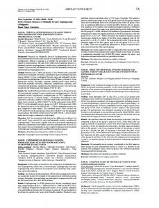
Figure 2. (a) Sample raw 2D projection of the coronary arteries obtained during the CT scan. (b) an MPR image of the 3D coronary arteries. (c) MIP of the coronary arteries. The arrows indicate; i) the outflow from aortic root, ii) the leftventricular cavity, where the contrast agent was present during imaging. iii) the artery that supplies the atrioventricular node, a characteristic feature of leftdominant circulation. 3.3 Implementation This set of dynamic vectors was then used to drive a thin-plate-spline based nonlinear warping algorithm to deform the 3D static image of the coronary arteries between time points in the cardiac cycle [12]. For the purposes of the work presented here, the point constraints used in the non-linear warping algorithm are the bifurcation landmarks identified on the 3D CT image and the corresponding landmarks determined from the cine bi-plane images. Each deformation was performed with respect to the original 3D CT image to minimize the image degradation associated with successive deformations. 3.4 Results The 3D CT image of the excised human heart, which displayed anatomical characteristics of left-dominant circulation, is shown in Figure 2. Figure 2a is one of the projection radiographs acquired during the CT scan and used in the reconstruction of the 3D image. Figure 2b shows a multi-planar reformatted (MPR) image identifying the coronary arteries and the myocardium. Note that because the heart was suspended in a saline bath there is little contrast between the myocardial muscle and the surroundings. A maximum-intensity projection (MIP) of the 3D image is shown in Figure 2c, highlighting some of the features of the excised heart used in this experiment. Assessing the MPR images of the excised heart in Figure 2b and the cine bi-plane angiograms from the cardiac patient, eighteen major arterial bifurcations were extracted from the images with acceptable accuracy. Locating the landmarks in both the LAO and RAO planes gave the necessary information to map the 2D coordinates of the landmarks into 3D space.
374
G. Lehmann et al.
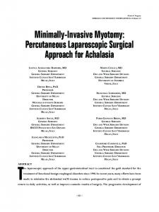
Figure 3. a) an overly of 2 MIPs of the deformed 3D CT images showing the dynamic nature of the model. b) a segmented version of the dynamic 3D CT image integrated into the VCSP platform. c) a virtual endoscopic view of the segmented heart. The non-linear warping algorithm was then implemented based on the eighteen dynamic landmarks. The fidelity of the deformation algorithm was first evaluated qualitatively by comparing MPRs through the deformed volume images with equivalent MPRs from the original 3D CT image. To demonstrate the dynamics of the coronary-artery model, overlayed MIPs of the 3D images are shown in Figure 3a.
4. Summary The two themes presented above are both part of a feasibility study aimed at evaluating techniques that could be incorporated into a virtual environment to plan, train and guide robotically-assisted cardiovascular surgery procedures. We have demonstrated that in a static environment, prediction of target positions on the myocardium can be achieved with a precision of 3mm, and that we can animate a static heart model such that the dynamics of the vascular structures can be modeled with approximately the same precision. While here is still much room for improvement, we believe that the combination of the cardiac animation procedure, using gated angiograms acquired in the OR during surgery, can effectively animate a cardiac model within the virtual surgical environment. The VCSP platform and the virtual heart model will be valuable tools in the development of a dynamic virtual representation of the patient’s thorax. While many limitations exist and integrating the virtual heart model into the VCSP will be an important step towards achieving our ultimate goal, our preliminary results are demonstrated in Figure 3. Our ultimate goal is to use the techniques described above to animate a finite-element model of a patients heart which would be integrated with the VCSP environment.
Minimally Invasive Robotic Cardiac Bypass Surgical Procedures
375
Acknowledgements We acknowledge support for this project from the Canadian Institute for Health Research (CIHR) and the Heart and Stroke Foundation of Ontario (HSFO). We also acknowledge our college Ravi Gupta for his technical assistance in this project.
Bibliography 1.
Subramanian, V. A., McCabe, J. C., and Geller, C. M., "Minimally invasive direct coronary artery bypass grafting: two-year clinical experience," Ann. Thorac. Surg., vol. 64, no. 6, pp. 1648-1653, Dec.1997. 2. Diegeler, A., Falk, V., Matin, M., Battellini, et al., "Minimally invasive coronary artery bypass grafting without cardiopulmonary bypass: early experience and follow-up," Ann. Thorac. Surg., vol. 66, no. 3, pp. 1022-1025, Sept.1998. 3. Pagni, S., Qaqish, N. K., Senior, D. G., and Spence, P. A., "Anastomotic complications in minimally invasive coronary bypass grafting," Ann. Thorac. Surg., vol. 63, no. 6 Suppl, pp. S64-S67, June1997. 4. Loulmet, D., Carpentier, A., d'Attellis, N., et al., "Endoscopic coronary artery bypass grafting with the aid of robotic assisted instruments " J. Thorac. Cardiovasc. Surg., vol. 118, no. 1, pp. 4-10, July1999. 5. Reichenspurner, H., Boehm, D. H., Gulbins, H., et al., "Robotically assisted endoscopic coronary artery bypass procedures without cardiopulmonary bypass," J. Thorac. Cardiovasc. Surg., vol. 118, no. 5, pp. 960-961, Nov.1999. 6. Ducko CT. Robotically – assisted coronary artery bypass surgery: moving toward a completely endoscopic procedure. Edward R.Stephenson, Jr MD1 Sachin Sankholkar MS2 Ralph J. Damiano Jr MD1. Heart Surgery Forum 2[1]. 9-2-1999. 7. Louai, A., Coste-Manière, E., Boissonnat J.D., "Planning and Simulation of Robotically Assisted Minimal Invasive Surgery", MICCAI 2000, 1935, 624-633. 8. Chui, A. M., Dey D., Drangova, M., Boyd, W.D., and Peters, T.M., “3D Image Guidance for Minimally Invasive Robotic Coronary Artery Bypass (MIRCAB)”, Heart Surgery Forum, 3(3):224-231, 2000. 9. Slomka, P. J., Hurwitz, G. A., and Stephenson, J. A volume-based image registration toolkit for automated comparison of paired nuclear medicine images. Med Phys 22. 1995. 10. Tabaie,H. A., Reinbolt, J. A., Graper, W. P., et al. "Endoscopic coronary artery bypass graft (ECABG) procedure with robotic assistance." Heart Surgery Forum 2(4): 310-317, 1999. 11. Fahrig, R., Fox, A. J., Lownie, S., and Holdsworth, D. W. Use of a C-arm system to generate true three-dimensional computed rotational angiograms: preliminary in vitro and in vivo results. AJNR Am J Neuroradiol 18 (8), 1507-14. 1997. 12. Bookstein F.L., "Principal warps: Thin-plane splines and the decomposition of deformations," IEEE Transactions on Pattern Analysis and Machine Intelligence, vol. PAMI-11, no. 6, pp. 567-585, 1989.