Towards effective modeling and programming multi-core tiled reconfigurable architectures Kenneth C. Rovers, Marcel D. van de Burgwal, Jan Kuper, and Gerard J.M. Smit Computer Architecture for Embedded Systems group, CTIT, Department of EEMCS, University of Twente, Enschede, The Netherlands
[email protected], http://caes.cs.utwente.nl/Research/?project=BeamForce
Abstract— For a generic flexible efficient array antenna receiver platform a hierarchical reconfigurable tiled architecture has been proposed. The architecture provides a flexible reconfigurable solution, but partitioning, mapping, modeling and programming such systems remains an issue. We will advocate a model-based design approach and propose a single semantic (programming) model for representing the specification, design and implementation. This approach tackles these problems at a higher conceptual level, thereby exploiting the inherent composability and parallelism available in the formalism. A case study illustrates the use of the semantic model with examples from analogue/digital co-design and hardware/software co-design. Keywords: Phased array beamforming, reconfigurable tiled architecture, semantic programming model, model-based design
1. Introduction When designing a mixed signal system the traditional approach uses mathematics for analysis, SysML/UML for (system) modelling, Simulink for hardware simulations and SystemC for software simulations/implementations [1], [2], [3], [4]. This means a number of tools are used, each of which has it’s own model. This complicates holistic iterative system design and makes the trade-off of what to do in the analogue domain and what to do in the digital domain more difficult. A single model and tool would be beneficial. Simulink is the de-facto standard for block-diagrams models based on mathematics. However, as we will discuss, Simulink is less suitable for digital hardware, in our case a tiled multi-processor architecture, where architecture definition, reconfiguration and programming come into play. For a reconfigurable system, the architecture must support multiple applications or configurations and the models must aid in their design. System design is greatly aided by the use of models, which provide an abstraction at different levels of detail or functionality. The models can also complement each other by providing different views of the system. In hardware, model-based design uses building blocks to define functional characteristics of the system at various degrees of sophistication, allowing simulation, testing and verification of systems [1]. In software, this approach This research is partly funded by Thales Netherlands and STW projects CMOS Beamforming (07620) and NEST (10346).
is called the model-driven architecture approach [2]. In order to decouple the system design from an architecture, a high level model should be architecture independent and a model transformation can be applied to create an architecture dependent model. We will advocate a model-based design approach and propose a single semantic (programming) model based on mathematics. This model can be evaluated for example for simulation purposes. Effectively using and programming MPSoCs is difficult [5]. We will show how to develop a semantic model for a simple beamforming application into an implementation for a reconfigurable tiled MPSoC, and how to evaluate different architecture alternatives with it. After an introduction to the application domain and the used platform for our case study, the commonly used design approach for such systems and its limitations is presented. Next the “semantic (programming) model” is proposed for representing the specification, design, and implementation with a single model. Finally, a case study is presented in which we will compare the traditional approach (in the form of a mathematical analysis with a Simulink model) with the semantic model approach.
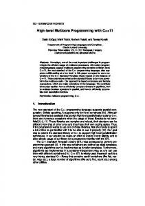
1.1 Application Domain To illustrate the model-based design approach, we use a phased array receiver platform as an example of a high performance digital signal processing (DSP) application. The current design of these systems is mainly driven by functional requirements (e.g., resolution, sensitivity, response time) where non-functional requirements (e.g., costs, power consumption) are of secondary concern [6]. In areas like radio astronomy and for satellite receivers, phased array antennas show great promise. For example, a cheaper or higher resolution SKA (square kilometer array [7]) or a flat less obstructive electronically steered multisatellite receiver. However, their large scale introduction has been obstructed by the high costs involved. The goal is thus to develop a low-cost, low-power flexible phased array receiver system. The system blocks of a basic phased array system are shown in Fig. 1. In a phased array receiver, signals are received at multiple antennas with different time delays (or phase shifts) because of path length differences. Typically hundreds of antennas are used. After the RF (radio frequency) front end for each antenna, antenna processing (AP) may be applied for calibration or equalization purposes. The signals are then combined by
• Multi-core reconfigurable processing on a (singl CMOS chip (MPSoC) • Processing close to antenna • Multiple hierarchical levels
ψc
AP
d ∆l
evalu tion a
sim
ulation model
e
RF
ψc
AP
DOA
BS
Beam-control
Fig. 1: Phased array receiver and angular sensitivity the beamforming processing (beamformer). Beamsteering (BS) refers to changing the shape and direction of the formed beam by changing the gain and delay of the antenna signals to create a certain angular sensitivity or radiation pattern as shown in Fig. 1. Note that multiple beams in different directions can be formed by re-using the antennas signals and applying the beamforming for each beam with different correction parameters. To calculate the parameters, the beamsteerer needs to know in which angle (direction) to point the beam. This information is provided by the beam control process.
1.2 Reconfigurable Tiled Architectures Phased array processing can be characterised as a streaming application with high data rates and processing requirements, but a regular processing structure. Because of costs, complexity, dependability, and scalability reasons, a design with mostly identical components is preferred, but because of functionality with different requirements and use, it will be heterogeneous. We would like to limit the data rate as soon as possible through beamforming, because I/O is expensive. This implies that the processing is moved closer to the antennas. However, combined data cannot be separated later on, so we loose flexibility. Furthermore, the distributed processing must be synchronised. Because a scalable and dependable solution is needed, a tiled architecture is proposed with reconfigurable cores to regain flexibility. Processing tiles are combined on multiple hierarchical levels. A multi-processor system-on-chip (MPSoC) can be extended to multiple chips on a board (MCoB) and multiple boards in a system (MBiS) giving a heterogeneous hierarchical tiled architecture (Fig. 3). We aim at a processing architecture which is flexible enough to support multiple methods of beamforming, as well as beamsteering and beam-control. [8] A reconfigurable hierarchical processing array can provide flexibility and has a number of advantages. We can use only part of the array or create multiple sub-arrays
valuation ver tion ificat ion valida
Fig. 2: Model driven design
Signal Processing
processing
RF
Antenna Tile
processing
incremen to
t
Antenna Tile digital
se
aly s
mathem at an ical
p -d o
ntation
goals
t
pleme
+
ron
funct ion al m
rative ite wn
wa ve f
requ irem e re nt
ψc
AP
im ment t en lop ementation e ev el & impl s od h esi nt
RF
analogue
! distributed processing dev ation safety !ecificfail elo pm sp h s d rc scalability l a! e od sy is l !m partitioning a
Beamformer
based/ Fig. 3: Heterogeneous hierarchical tiled architecture
Informati
http://caes.cs.utwente.nl/Research/?project=Beamforce
[email protected] save energy or increase the lifetime. Reconfigurability (also in I/O routing) supports graceful degradation if tiles break down. Reconfigurability inherently leads to having an adaptive system, that adapts to changing environments while maintaining the quality of service. In our view, a configuration keeps the functionality of the system fixed for some time while in operation. After some time the system can be reconfigured to change (parts of the) functionality. For example, for the beamforming application, small scale reconfiguration (with respect to impact as well as passed time) can consist of new beamsteering parameters. Medium scale reconfiguration can be a different mapping of the application or changing the beamforming or tracking method (e.g. due to the weather or mobility). Large scale reconfiguration could consist of chaning to direction of arrival estimation, using sub-arrays or multi-function radar.
1.3 Related work To the best of our knowledge, there is no comparable work that proposes a single model based on a functional language for system design using a model based design approach. The Ptolemy project [9] studies design, modeling and simulation of concurrent, real-time, embedded systems and has therefore similar goals. The project provides a framework for system simulation and focusses on experimenting with different models of computation and design. Models can be created using Java, XML or with a graphical tool. In contrast, we propose to stay close to the math and use a functional language to provide the framework. Furthermore we focus on a single model from design to implementation. Note that many features of Ptolemy such as type interference or data polymorphism are already available in a functional language. Reekie [10] also proposes and shows how to use a functional language for realtime signal processing using pipelined parallelism. He shares the same reasoning for this approach but mostly at the application level (digital processing implementation) and not extended to the system level. Reekie also presents Visual Haskell as a graphical programming language, complementary to the text-based functional programming language Haskell [11]. Functional Reactive Programming [12] is a paradigm for reactive programming in a functional setting. A Haskell extension is available for modeling continuous and discrete
systems. There are a number of dataflow languages such as Lustre or Lucid [13], which are close to functional languages and focus on programming signal processing, but do not support system design or simulation besides with the dataflow model of computation. A limitation, which is often not desirable for system design [9]. The model driven architecture approach proposes UML (unified modeling language) as the modeling language to use [2] and often SystemC is proposed for hardware implementation [4]. However, this approach is for software systems and digital hardware. SysML is more suitable for system engineering with Simulink de-facto standard for modeling and partly implementation [14], [3], [15]. Simulink [3] is a graphical language using blockdiagrams and continuous time differential equations as its model of computation. Discrete time support is implemented by the notion of sample time, where time is implicit. It is an environment for multi-domain simulation and model-based design for dynamic and embedded systems. It can work with hierarchical models and allows for code generation in C or VHDL. We will compare our approach to a Simulink model for the case study.
mathematical/ dataflow model
constraints
mathematical/ dataflow model
architecture definition
partitioning
architecture definition
mapping
mapping
implementation
implementation
Fig. 4: Y-chart co-design
constraints
Fig. 5: L-chart co-design
2.3 Hardware/Software Co-Design
Model based-design is based on incremental and iterative design instead of the traditional waterfall model [1], allowing integration of parts as soon as possible and extending the design with small steps. The design steps (or cycles) consist of setting goals, doing research and doing development (i.e. why, what and how), followed by an evaluation (Fig. 2).
Processing systems often have a trade-off between what to do in hardware and what in software. Hardware refers to specific functionality with limited flexibility, but high efficiency (area, power, performance, cost), while software refers to some kind of processor which can be programmed and is therefore much more flexible, but at the cost of efficiency. Hardware/software co-design refers to defining an architecture, and mapping functionality to hardware and software for this architecture. Thereby balancing the tradeoff between flexibility and efficiency. A mathematical or dataflow model provides the functionality, while an architecture provides the means, in our case a mixed signal MPSoC. An Y-chart approach (Fig. 4) [16] is used for mapping, i.e. functionality is assigned to specific hardware and the assigned blocks are connected together. The resulting implementation often has the (digital) hardware specified by a language such as SystemC or VHDL and the software in C.
2.1 Common Design Approach
2.4 Evaluation
A typical design approach uses systems engineering [1] with the analysis (goals and research), synthesis (development and implementation) and evaluation (verification and validation) steps. Setting the design goals and defining the requirements is supported by using diagrams of a modeling language such as SysML or UML. Besides these models, a mathematical model is used for formal specification and for simulation. In the development phase a simulation model, for example in Simulink, can be used to evaluate design decisions and implementations by testing. The implementation consists of block schematics, hardware and/or software.
Apparent from the previous sections is that in standard practice different tools and languages are used for the specification, mathematical model, simulation model, and implementation, although of course they overlap to some degree. One of the major problems is that a specific implementation (for example in C and for an ARM processor) can not easily be integrated into the simulation model. Although it is possible to execute UML or to generate code from UML, it is focussed on software and needs tool support. Simulink is used for mathematical analysis and modeling, but the block-diagrams and implicit time is limiting for analogue-digital co-design. Furthermore, it is difficult to evaluate design alternatives. A single model needs continuous and discrete time, and dataflow support, which is not directly offered by Simulink. Below we will start from mathematics and develop a more flexible approach. The architecture must be flexible enough to support different functionalities after reconfiguring. The factors involved in defining the architecture make it likely that different alternatives need to be evaluated, but the tools lack support for easy evaluation. Instead of defining the functionality and architecture separately, we propose the L-chart approach (Fig. 5). We can now define the architecture based on partitioning the functionality and
2. Model Based/Driven Design
2.2 Analogue/Digital Co-Design Analogue design uses continuous time mathematical models, where time is explicit and values have an (almost) infinite resolution. Going to the digital domain involves sampling and quantisation. Digital design uses discrete time models, which involves choosing a representation, such as fixed or floating point and determining the required accuracy. In the digital domain time is implicit and defined by the sample times of the data values. Digital signal processing models often use a dataflow representation. Therefore, for analogue/digital co-design, different models of computation must be supported.
the required performance figures (constraints) such as throughput, latency and “cost”. A major problem for multi-core and multi-processor systems is how to program them efficiently. Often the parallelisability of an algorithm is limited by the implementation language used. This is because imperative programming languages, such as C, are inherently sequential and it is difficult to determine wether a used variable (memory location) does not change when being used somewhere else. Especially in the DSP domain, it is best to stay close to the math as to not unnecessarily restrict or obscure the available parallelism.
3. Semantic (Programming) Model We believe a single model should be used to provide the formal and functional specification of a design, as well as allowing one to develop this model into an implementation. A model-based design approach can then be used with a single model for specification, verification, simulation and implementation. We dubbed this a “semantic model” as the model itself can be the specification, an abstraction as well as an implementation, all with the same intended meaning. It is also a programming model as it can be used as a programming language for a processor, an MPSoC, or even hardware. This belief is based on the notion of “the code is the design”, and on the notion that a mathematical model can describe the system. MATLAB and Simulink are languages for mathematical computation, analysis and modeling. However, this is not extended down to being a full-featured programming language. Imperative programming languages on the other hand are not very suitable as a mathematical model, because it provides a sequence of statements, while a mathematical model consists of equations. There are programming languages that describe a set of functions instead of a sequence of statements, called functional languages. The functional language allows one to naturally and directly implement the mathematics, which is the starting point in the application domain, and which can be executed or run as the simulation. In the past functional languages were used for sequential computer architectures, which leads to poor performance. Today we have to write code for parallel architectures where functional programs are beneficial. The functional program is partitioned using (directly supported) mathematical transformations, which therefore constitute a formally correct refinement of the specification. Function composition allows for composability and partitioning allows for distribution, as illustrated by the case study.
4. Case Study The design of a flexible array receiver platform is used as a case study. After the design goals, a mathematical model of a phased array beamforming system is presented, which we develop using the iterative model-based design approach. Simulink is used to compare against our semantic model.
4.1 Goals We would like to design a digital beamforming system supported by a realistic simulation of the system with an ideal analogue front-end. We propose a tiled architecture with tiles which are reconfigurable to perform different functionalities. The amount of tiles and different options of beamforming processing are to be evaluated.
4.2 Mathematical Model Phased array systems use multiple antennas in an array to make a receiver directional (Fig. 1). Assume a single omni-directional wave source, emitting a spherical waveform in time and space s(t, l) = A·cos(ωt±kl), with A the amplitude, ω the frequency, k the wave number, t time and l the path length from the source. For a source in the far field perpendicular to the array, the wavefront is considered planar. If the plane of the array is not perpendicular, the wavefront arrives at different times at the antennas (Fig. 1). If the antennas are placed a distance d apart and the wavefront arrives at an angle ϑ incident to the array, the wavefront travels a distance d · sin (ϑ) further to the next between antenna, resulting in a time delay ∆t = d·sin(ϑ) c the signals (c is the propagation speed). Depending on the frequency of the wave, this time delay results in a phase shift (∆ψ = ω · ∆t) giving rise to the term “phased array”. By correcting the delay we can steer the direction of maximum sensitivity [6]. Based on the radar equation [17], the resulting signal after beamforming can be represented by the source S(t), an element factor Se depending on the sensitivity of each antenna element, an array factor Sa depending on the element positions, a correction (steering) factor Sc and a combining sum: X S= S(t) · Se (θ, ϕ) · Sa (l) · Sc (θ0 , ϕ0 ) X = a · ej(ωt±ψe (θ,ϕ)±kl±ψc (θ0 ,ϕ0 )) (1) ψc (θ, ϕ) = k · (−∆l(θ0 , ϕ0 )) = ω · (−∆t(θ0 , ϕ0 )) (2) ~ = dx · u + dy · v + dz · w ∆l = ~r · R
(3)
~ the plane wave with ψ the phase, ~r the element position, R direction, u, v, w the direction cosines and −∆t(θ0 , ϕ0 ) the time delay correction [6], [17], [18]. Without going into further details, these equations form the standard model of phased array beamforming.
4.3 Model Based Design Equation 1 is based on a model of the system as a source, a transmitter, a channel, and a receiver, followed by a beamformer. The array factor is dependent on the length from the transmitter to the receiver and is modeled by the channel between them, using equations 2 and 3. The correction factor and the sum together form the beamforming operation. Note, that there we assume one source, transmitted over multiple elements with their individual element factors, array factors and correction factors. The sum combines all these factor contributions again into a single signal.
data data data data
Sig DOA Pos BSt
= = = =
S D P B
( Float ( Float ( Float ( Float
−> F l o a t −> F l o a t ) F l o a t F l o a t , Float , Float ) , Float , Float ) , Float )
source t = S ( sine f a ) g t s i m u l a t i o n = map s y s t m ( map s o u r c e t s ) s y s t m : : S i g −> [ F l o a t ] s y s t m s = ( f r o n t e n d d p s >> b e a m f o r m e r b s p s ) s f r o n t e n d : : DOA −> [ Pos ] −> S i g −> [ F l o a t ] f r o n t e n d d p s s = mapf ( map ( c h a i n d ) p s ) s
Fig. 6: Simulink phased array functional model 4.3.1 Simulink model The functional model implemented in Simulink is shown in Fig. 6. The single signal of the source is multiplied with a vector of the gain of each antenna element. Note that we have multiple receivers, each having its own channel from the source with a different path length, taken care of by the data structure between each block, which is not directly evident from the model. In essence, a new matrix dimension is added to the data going through the model for the time, the elements, and the beams. 4.3.2 Semantic Model The semantic model consists of a functional program (in Haskell [11]). The functions can model the component or (sub-) blocks of a design, connected by function composition and allowing composability. Functions are defined by a name followed by the arguments of the function. By using higher order functions, functions themselves can be used as arguments. The type of the arguments is defined after the :: operator. New types are defined with the data keyword. Equation 1 can be implemented straightforward (see listing 1 and 3); the function names correspond to the block names of the Simulink model. Furthermore, the chain, frontend and systm model compositions (explained below), which in Simulink are hidden in the datastructure send from block to block. We defined types to represent a signal (Sig), a direction of arrival (DOA), an element position (Pos), and a beam-steer direction (BSt). The map function applies a function to each argument of a list. By mapping the source signal over a list of time instants, we create a list of the signal over time, which we can use as input to the system to perform a simulation. The listing can be run, thereby performing a simulation with results as expected. A single source goes to a separate transmitter, channel, and receiver chain for each element. All chains together form the frontend, which uses the map function to create such a chain for each element. The mapf function is used to provide the same source signal (s::Sig) to each chain by mapping the list of frontend chains over the source function. The output of the frontend is provided as input to the beamformer block with the pipe operator (», see listing 2), which simply performs a function composition. The frontend and the beamformer form the systm, which expects a signal as input and gives a beamformed result for each beamsteering vector provided.
c h a i n : : DOA −> Pos −> S i g −> F l o a t c h a i n d p s = ( t r a n s m i t t e r d p >> c h a n n e l d p >> r e c e i v e r d p >> a d c ) s
Listing 1: Phased array semantic model ( f >> g ) x = ( g . f ) x = g ( f ( x ) )
Listing 2: Pipe operator c h a n n e l : : DOA −> Pos −> S i g −> S i g c h a n n e l (D ( r , a , e ) ) ( P ( x , y , z ) ) ( S s g t ) = ( S s g ( t +d ) ) where d = s q r t ( ( x* s i n a ) ^2+( y* s i n e ) ^2+( z / c ) ^2) a d c : : S i g −> F l o a t adc ( S s a t ) = ( s a t )
Listing 3: Channel and ADC implementation 4.3.3 Comparison The semantic model is implemented quite naturally with function applications and concatenation modeling system components and math for the implementation. The language can model the composability of the system. A system consists of a piped frontend and beamformer block. The frontend is a collection of chain blocks. A single chain block consists of a pipe of transmitter, channel, receiver and adc blocks. Also interesting is that the flow of data can be seen by the parameters passed from block to block such as Sig, while other parameters are fixed parameters, which are directly provided as function arguments such as Pos. The Simulink model is more intuitive as it is a graphical block-diagram representation, which has simple semantics, but is much more difficult to implement. The semantic model thus improves productivity.
4.4 Analogue/Digital Co-Design In the design continuous time is used up to the ADC block. Beamforming is performed in discrete time/digital. In Simulink, the channel is modeled with a variable time delay block and a delay vector, which implements the time delay caused by different path lengths between the source and the antenna. Simulink uses numerical algorithms to compute the dynamic behaviour. One problem with this approach is that for each block a sample-rate (simulation rate) is determined and the equations are evaluated for each of these sample time. At this time the model is thus discretized. Although Simulink supports multi-rate models, this is problematic in case of very different sample rates, such as for example down-conversion in an RF front-end. The lower sample rate blocks need to be evaluated with a much higher sample rate than otherwise needed, making
the simulation slow. Another problem is a variable time delay, such as needed for the channel. The variable time delay block buffers values for each simulation time step until the delay. If the delay is not exactly at a sample time, the value is interpolated between two point, thus resulting in inaccuracies for the channel block implementation. This is detrimental for example for the nulls of the beamformer. Also, the ADC is implemented with a sample and hold block, operating at the ADC sample rate, even though the sample rate of Simulink might be different/higher. Saturation and quantization are not taken into account. For the semantic model, listing 3 shows how a signal going through the channel is changed according to equation 2. For each channel, the path length from source to antenna is different, depending on the element position (P (x,y,x)) and source location (D (r,a,e)), and resulting in a time delay for the signal. The calculation of the delay (d) is provided by the where clause of the channel. It is then simply added to the time parameter t of the signal (S s g (t+d) :: Sig). The variable time delay is thus just a change of time argument t and is therefore exact. The adc explicitly evaluates the source function by applying the function to a time argument. Higher order functions allow the explicit modeling of time as a parameter of signal functions instead of implicit time modeling in a tool such as Simulink, where signal values at a time instance are used. The channel function also illustrates the ideal functional behaviour of the channel modeled by a mathematical equation. The whole frontend model operates by making changes to the source signal parameters. The signal is passed from block to block by the semantic model, until it is explicitly evaluated by the adc to a value at a specific time (specified by the list of time values ts). After the adc block, time is thus implicit.
4.5 Hardware/Software Co-Design As an example of Hardware/Software Co-Design, we implement the correction and sum of the beamforming block using the L-chart approach (Section 2.3). We will first discuss a direct implementation, followed by a partitioning into multiple tiles and a partitioning with constraints. We compare on processing and communication costs. Multiplication has a cost of 10 and addition of 1. The communication cost is the number of inputs and outputs. 4.5.1 Single Tile A direct implementation of the beamforming block consists of multiplying each input element with a correction factor followed by a sum. This is shown in listing 4, where the correction factors cs are assumed known and the list ss contains the samples of the antennas at a certain sample time. The function zipwith performs a element-wise multiplication of the lists cs and ss and sum sums the results. The operator # gives the length of a list. If we assume a single tile for the architecture, with 64 antennas and suppose we want to determine one beam, then the tile has a processing cost of 64∗10+63∗1 = 703 and a communication cost of 64 + 1 = 65.
beamform : : [ F l o a t ] −> [ F l o a t ] −> F l o a t beamform c s s s = sum ( zipWith ( * ) c s s s ) / # s s
Listing 4: Single tile - Multiply and sum implementation sumn n x s | # xs


![[PDF]EPUB Parallel Programming: For Multicore and ... - Google Sites](https://m.moam.info/img/260x300/pdfepub-parallel-programming-for-multicore-and-goo_64785b0b097c474c228d0b73.jpg)

