Håkansson, Paul Pettersson, Ivica Crnkovic. In Proceedings of ...... [33] Mikael ˚Akerholm, Jan Carlson, John Håkansson, Hans Hansson, Mikael. Nolin, Thomas ...
M¨alardalen University Press Licentiate Theses No.111
Towards Efficient Component-Based Software Development of Distributed Embedded Systems
S´everine Sentilles 2009
School of Innovation, Design and Engineering
c S´everine Sentilles, 2009 Copyright ISSN 1651-9256 ISBN 978-91-96135-43-0 Printed by M¨alardalen University, V¨aster˚as,Sweden
Abstract The traditional ways of developing embedded systems are pushed to their limits, largely due to the rapid increase of software in these systems. Developers now have difficulties to handle simultaneously all the factors involved in the development such as increasing complexity, limited and shared resources, distribution, timing or dependability issues. These limitations make the development of embedded systems a rather complex and time consuming task, and call for new solutions that can efficiently and predictably cope with the new specifics and requirements of embedded systems to ensure their final quality. Component-based software engineering is an attractive approach that aims at building software systems out of independent and well-defined pieces of software. This approach has already shown advantages in managing software complexity, and reducing production time while increasing software quality. However, directly applying component-based software engineering principles to embedded system development is not straightforward. It requires a considerable adaptation to fit the specifics of the domain, since guaranteeing the extra-functional aspects, such as real-time concerns, safety-criticality and resource limitations, is essential for the majority of embedded systems. Arguing that component-based software engineering is suitable for embedded system development, we introduce a component-based approach adjusted for embedded system development. This approach is centered around a dedicated component model, called ProCom, which through its two-layer structure addresses the different concerns that exist at different levels of abstraction. ProCom supports the development of loosely coupled subsystems together with small non-distributed functionalities similar to control loops. To handle the management of important concerns related to functional and extra-functional properties of embedded systems, we have extended ProCom with an attribute framework enabling a smooth integration of existing analysis techniques. We have also demonstrated the feasibility of the approach through a prototype realisation of an integrated development environment. i
R´esum´e — Abstract in French Affrontant une rapide et massive introduction de logiciels, le monde des syst`emes embarqu´es est en proie au changement. De ce fait, les m´ethodes traditionnelles de d´eveloppement de ces syst`emes atteignent leurs limites. Elles ont d´esormais des difficult´es a` g´erer simultan´ement tous les param`etres impliqu´es dans le d´eveloppement, tel que l’accroissement de la complexit´e, la limitation et le partage des ressources, la distribution, ainsi que les contraintes temporelles et de fiabilit´e. Ces limitations rendent le d´eveloppement particuli`erement complexe et coˆuteux, et requi`erent de nouvelles solutions pouvant efficacement et de mani`ere pr´evisible r´epondre aux nouveaux besoins des syst`emes embarqu´es afin d’assurer leur qualit´e finale. L’ing´enierie logicielle bas´ee composants est une approche visant a` la construction de syst`emes logiciels par l’usage de “briques logicielles” ind´ependantes et parfaitement caract´eris´ees. Cette approche a d´ej`a d´emontr´e des aptitudes pour appr´ehender la complexit´e logicielle tout en r´eduisant les temps de production et maintenant la qualit´e. Pourtant appliquer directement les principes de l’ing´enierie logicielle bas´ee composants au d´eveloppement de syst`emes embarqu´es n’est pas simple et n´ecessite une adaptation consid´erable pour se conformer aux exigences du domaine, telles que la limitation des resources et les contraintes temps r´eel et de criticit´e. Convaincus que l’ing´enierie logicielle bas´ee composants convient au d´eveloppement des syst`emes embarqu´es, nous introduisons une approche bas´ee composants dedi´ee au d´eveloppement de syst`emes embarqu´es. Cette approche s’appuie sur ProCom, un mod`ele de composants sp´ecifique qui au travers de sa structuration en deux niveaux concerne les propri´et´es pr´esentes a` diff´erents niveaux d’abstractions. ProCom supporte le d´eveloppement de sous-syst`emes iii
iv
faiblement coupl´es conjointement avec de petites fonctionnalit´es non distribu´ees analogues aux boucles r´etroactives. Dans le but d’assurer la gestion des aspects ayant trait aux propri´et´es fonctionnelles et extra-fonctionnelles, nous avons e´ tendu ProCom au travers d’un “attribute framework” facilitant l’int´egration de techniques d’analyses pr´eexistantes. La faisabilit´e de l’approche est e´ galement d´emontr´ee via la r´ealisation d’un prototype d’environnement de d´eveloppement int´egr´e.
Acknowledgements Looking back at my past, nothing predestined me to do a thesis and even less in Sweden, a country that I would have never envisaged to live in (“it is too cold up there !!!”). But the course of my life completely changed thanks to Nicolas Belloir, who put his trust in me and always tried to pushed me forward, smoothly enough to manage to make me accept a PhD position at M¨alardalen University. I cannot say how much I am thankful to you for this: you are a great friend! But this adventure would not have been possible nor been as enjoyable either without the intervention of many people. To begin with, I would like to express my gratitude towards two of my supervisors, Ivica Crnkovic and Hans Hansson. Thank you for believing in me and accepting me as a PhD student despite my hesitating Frenglish way of speaking. I am always amazed by your enthusiasm, commitment and above all your inexplicable capacity to work so much. Many thanks also go to my other supervisor, Jan Carlson, for all the fruitful discussions, inputs, reviews, help and guidance every time I needed it. I also want to thank my French supervisors, Frank Barbier and Eric Cariou, who have given me the opportunity to do a so-called “co-tutelle” with the university of Pau. Many thanks also go to the “Mental Department” that many have tried to enter but few have managed, ProPhs and associated members (Cristina, Stefan/Bob, H¨us, Tibi, Adnan, Aida, Aneta, Luis, Batu, Farhang, Hongyu, Pasqualina, Juraj, Mikael, Antonio, Ana, Luka, Leo, Marcelo, Jagadish) for all the laughters and great moments during the fika, lunches and travels. You are really great people to work with, and above all great friends. And of course, I don’t forget all the P ROGRESS and/or IDT members, Andreas, Damir, Daniel, ˚ Lars, J¨orgen, Mikael Akerholm, Radu, Nolte, Markus, Ebbe, Anton, Rikard, ˚ Stig, Frank, Paul, Jukka, Sasi, Malin, Gunnar, Asa, for making life at work and abroad so pleasant! v
vi
I would also like to put a special mention to Harriet Ekwall and Monica Wasell not only for continuously helping out on an every-day basis and bringing so much fun in the department but also for all the help they provided me when I arrived in this foreign country and I was totally lost and confused with the administrative procedures. The atmosphere at the department will definitively not be the same without you. There are also a lot of friends from childhood and university that I really want to thank for having been present for me when i really needed support and good friends: Anouk, Flo, Natacha, Aurel, Cristine, Fafou, Eric, Gael, Sophie, Marie, Pauline, Laure, Aude, Anne-Sophie and Bea. I must say that I am really lucky to have you around. And last but not least, I would like to thank my parents, grand-parents, cousins (Yan, Aur´elie, C´edric, Alex, Lou-Anne), Marie-Franc¸oise, Marie-Paule, Fredo, Nono, and of course Dag and Liv for bringing so much to my life that I cannot express this with words. S´everine Sentilles V¨aster˚as, November 2009
This work has been supported by the Swedish Foundation for Strategic Research (SSF), via the research centre P ROGRESS.
List of Publications Publications Included in the Licentiate Thesis1 Paper A: A Classification Framework for Component Models. Ivica Crnkovi´c, S´everine Sentilles, Aneta Vulgarakis, Michel Chaudron. Accepted to IEEE Transactions on Software Engineering (in the process of revision). Paper B: A Component Model Family for Vehicular Embedded Systems. Tom´asˇ Bureˇs, Jan Carlson, S´everine Sentilles, Aneta Vulgarakis. In Proceedings of the 3rd International Conference on Software Engineering Advances (ICSEA), Sliema, Malta, October 2008. Paper C: A Component Model for Control-Intensive Distributed Embedded Systems. S´everine Sentilles, Aneta Vulgarakis, Tom´asˇ Bureˇs, Jan Carlson, Ivica Crnkovi´c. In Proceedings of the 11th International Symposium on Component Based Software Engineering (CBSE 2008), Karlsruhe, Germany, October, 2008. Paper D: Integration of Extra-Functional Properties in Component Models. ˇ ep´an, Jan Carlson and Ivica Crnkovi´c. In S´everine Sentilles, Petr Stˇ Proceedings of the 12th International Symposium on Component Based Software Engineering (CBSE 2009), LNCS 5582, Springer Berlin, East Stroudsburg University, Pennsylvania, USA, June, 2009. Paper E: Save-IDE – A Tool for Design, Analysis and Implementation of Component-Based Embedded Systems. S´everine Sentilles, Anders Pettersson, Dag Nystr¨om, Thomas Nolte, Paul Pettersson, Ivica Crnkovi´c. In Proceedings of the 31st International Conference on Software Engineering (ICSE), Vancouver, Canada, May 2009. 1 The
included articles have been reformatted to comply with the licentiate page setting
vii
viii
Additional Publications, not included in the Thesis Conferences and workshops: • Save-IDE — Integrated Development Environment for Building Predictable Component-Based Embedded Systems. S´everine Sentilles, John H˚akansson, Paul Pettersson, Ivica Crnkovi´c. In Proceedings of the 23rd IEEE/ACM International Conference on Automated Software Engineering (ASE), L’Aquila, Italy, September 2008. • Collaboration between Industry and Research for the Introduction of Model-Driven Software Engineering in a Master Program. S´everine Sentilles, Florian Noyrit, Ivica Crnkovi´c. In Proceedings of the Educator Symposium of the ACM/IEEE 11th International Conference on Model Driven Engineering Languages and Systems (MODELS), Toulouse, France, September 2008. • Valentine: a Dynamic and Adaptive Operating System for Wireless Sensor Networks. Natacha Hoang, Nicolas Belloir, Cong-Duc Pham, S´everine Sentilles. In Proceedings of the 1st IEEE International Workshop on Component-based design Of Resource-Constrained Systems (CORCS), Turku, Finland, July 28 - August 1, 2008. • A Model-Based Framework for Designing Embedded Real-Time Systems. S´everine Sentilles, Aneta Vulgarakis, Ivica Crnkovi´c. In the Proceedings of the Work-In-Progress (WIP) track of the 19th Euromicro Conference on Real-Time Systems (ECRTS), Pisa, Italy, July 2007.
MRTC reports: • ProCom – the Progress Component Model Reference Manual, version 1.0. Tom´asˇ Bureˇs, Jan Carlson, Ivica Crnkovi´c, S´everine Sentilles, Aneta Vulgarakis. MRTC report ISSN 1404-3041 ISRN MDH-MRTC-230/ 2008-1-SE, M¨alardalen Real-Time Research Centre, M¨alardalen University, June 2008.
ix
• Towards Component Modelling of Embedded Systems in the Vehicular Domain. Tom´asˇ Bureˇs, Jan Carlson, S´everine Sentilles, Aneta Vulgarakis. MRTC report ISSN 1404-3041 ISRN MDH-MRTC-226/20081-SE, M¨alardalen Real-Time Research Centre, M¨alardalen University, April 2008. • Progress Component Model Reference Manual - version 0.5. Tom´asˇ Bureˇs, Jan Carlson, Ivica Crnkovi´c, S´everine Sentilles, Aneta Vulgarakis. MRTC report ISSN 1404-3041 ISRN MDH-MRTC-225/2008-1SE, M¨alardalen Real-Time Research Centre, M¨alardalen University, April 2008.
To my grandfather
Contents I
Thesis
1
1 Introduction 1.1 Motivation . . . . . . . . . . . . . . . . . . . . . . . . . . . . 1.2 Objectives . . . . . . . . . . . . . . . . . . . . . . . . . . . . 1.3 Thesis Overview . . . . . . . . . . . . . . . . . . . . . . . . 2 Background 2.1 Embedded Systems . . . . . . . . . . . . . . . . . . 2.1.1 Characteristics in Vehicular Domain . . . . . 2.1.2 Characteristics in Automation Domain . . . . 2.2 Component-Based Software Engineering . . . . . . . 2.2.1 Extra-Functional Properties . . . . . . . . . 2.2.2 The Component-Based Development Process 2.2.3 Component-Based Software Engineering for ded System Development . . . . . . . . . . .
. . . . . . . . . . . . . . . . . . . . . . . . . . . . . . Embed. . . . .
3 Research Summary 3.1 Problem Positioning . . . . . . . . . . . . . . . . . . . . . . . 3.2 Research Questions . . . . . . . . . . . . . . . . . . . . . . . 3.3 Research Contribution . . . . . . . . . . . . . . . . . . . . . 3.3.1 A Classification Framework for Component Models . 3.3.2 Requirements for a Component-Based Approach . . . 3.3.3 The ProCom Component Model . . . . . . . . . . . . 3.3.4 Integration of Extra-Functional Properties in Component Models . . . . . . . . . . . . . . . . . . . . . . . 3.3.5 Prototype Implementation . . . . . . . . . . . . . . . 3.4 Methodology . . . . . . . . . . . . . . . . . . . . . . . . . . xiii
3 3 5 6 11 11 13 14 15 16 18 19 21 21 23 24 25 27 29 30 32 33
xiv
Contents
4 Related Work 4.1 Component Models . . . . . . . . . . . . . . . . . . . . . . . 4.2 Alternative Approaches . . . . . . . . . . . . . . . . . . . . . 4.3 Integrated Development Environment . . . . . . . . . . . . .
37 37 40 42
5 Conclusions and Future Work 5.1 Discussions . . . . . . . . . . . . . . . . . . . . . . . . . . . 5.2 Future Work . . . . . . . . . . . . . . . . . . . . . . . . . . .
45 45 50
Bibliography
53
II
61
Included Papers
6 Paper A: A Classification Framework for Component Models 6.1 Introduction . . . . . . . . . . . . . . . . . . . . 6.2 The Classification Framework . . . . . . . . . . 6.2.1 Lifecycle . . . . . . . . . . . . . . . . . 6.2.2 The Constructs . . . . . . . . . . . . . . 6.2.3 Extra-Functional Properties . . . . . . . 6.2.4 Domains . . . . . . . . . . . . . . . . . 6.2.5 The Classification Overview . . . . . . . 6.3 Survey of Component Models . . . . . . . . . . 6.3.1 “Almost” Component Models . . . . . . 6.3.2 Component Models . . . . . . . . . . . . 6.4 The Comparison Framework . . . . . . . . . . . 6.4.1 Lifecycle Classification . . . . . . . . . . 6.4.2 Constructs Classification . . . . . . . . . 6.4.3 Extra-Functional Properties Classification 6.4.4 Domains Classification . . . . . . . . . . 6.5 Related Work . . . . . . . . . . . . . . . . . . . 6.6 Conclusion . . . . . . . . . . . . . . . . . . . . 6.7 Appendix — Survey of Component Models . . . Bibliography . . . . . . . . . . . . . . . . . . . . . .
. . . . . . . . . . . . . . . . . . .
. . . . . . . . . . . . . . . . . . .
. . . . . . . . . . . . . . . . . . .
. . . . . . . . . . . . . . . . . . .
. . . . . . . . . . . . . . . . . . .
. . . . . . . . . . . . . . . . . . .
63 . 65 . 67 . 68 . 71 . 75 . 79 . 80 . 82 . 82 . 83 . 84 . 84 . 86 . 89 . 91 . 92 . 93 . 94 . 103
7 Paper B: A Component Model Family for Vehicular Embedded Systems 109 7.1 Introduction . . . . . . . . . . . . . . . . . . . . . . . . . . . 111 7.2 Motivating Example . . . . . . . . . . . . . . . . . . . . . . 113
Contents
7.3 7.4
The P ROGRESS Approach . . . . . . . . . . . . . . . Towards CBD in Vehicular Systems . . . . . . . . . . 7.4.1 From Abstract to Concrete . . . . . . . . . . . 7.4.2 Component Granularity . . . . . . . . . . . . 7.5 Conceptual Component Model Family . . . . . . . . . 7.6 Realization of the Proposed Component Model Family 7.7 Related Work . . . . . . . . . . . . . . . . . . . . . . 7.8 Conclusion . . . . . . . . . . . . . . . . . . . . . . . Bibliography . . . . . . . . . . . . . . . . . . . . . . . . .
. . . . . . . . .
. . . . . . . . .
. . . . . . . . .
xv
. . . . . . . . .
115 117 117 120 120 122 124 125 127
8 Paper C: A Component Model for Control-Intensive Distributed Embedded Systems 129 8.1 Introduction . . . . . . . . . . . . . . . . . . . . . . . . . . . 131 8.2 The ProCom Two Layer Component Model . . . . . . . . . . 132 8.2.1 ProSys — the Upper Layer . . . . . . . . . . . . . . . 132 8.2.2 ProSave — the Lower Layer . . . . . . . . . . . . . . 133 8.2.3 Integration of Layers — Combining ProSave and ProSys . . . . . . . . . . . . . . . . . . . . . . . . . 136 8.3 Example . . . . . . . . . . . . . . . . . . . . . . . . . . . . . 137 8.4 Conclusions . . . . . . . . . . . . . . . . . . . . . . . . . . . 138 Bibliography . . . . . . . . . . . . . . . . . . . . . . . . . . . . . 141 9 Paper D: Integration of Extra-Functional Properties in Component Models 9.1 Introduction . . . . . . . . . . . . . . . . . . . . . . . . . . . 9.2 Annotation of Attributes in Component Models . . . . . . . . 9.2.1 Attributes in a Component Model . . . . . . . . . . . 9.2.2 Attribute Definition . . . . . . . . . . . . . . . . . . . 9.2.3 Attribute Type . . . . . . . . . . . . . . . . . . . . . 9.2.4 Attribute Data . . . . . . . . . . . . . . . . . . . . . . 9.2.5 Multiple Attribute Values . . . . . . . . . . . . . . . . 9.2.6 Attribute Value Metadata . . . . . . . . . . . . . . . . 9.2.7 Validity Conditions of Attribute Values . . . . . . . . 9.3 Attribute Composition . . . . . . . . . . . . . . . . . . . . . 9.4 Attribute Configuration and Selection . . . . . . . . . . . . . 9.5 A Prototype for ProCom and the P ROGRESS IDE . . . . . . . 9.6 Related Work . . . . . . . . . . . . . . . . . . . . . . . . . . 9.7 Discussion . . . . . . . . . . . . . . . . . . . . . . . . . . . .
143 145 146 147 147 149 150 151 152 152 154 155 158 160 162
xvi
Contents
9.8 Conclusion . . . . . . . . . . . . . . . . . . . . . . . . . . . 164 Bibliography . . . . . . . . . . . . . . . . . . . . . . . . . . . . . 167 10 Paper E: Save-IDE – A Tool for Design, Analysis Component-Based Embedded Systems 10.1 Introduction . . . . . . . . . . . . . . 10.2 Software Development Process . . . . 10.3 Component-Based Design . . . . . . 10.4 Analysis . . . . . . . . . . . . . . . . 10.5 Synthesis . . . . . . . . . . . . . . . 10.6 Conclusion . . . . . . . . . . . . . . Bibliography . . . . . . . . . . . . . . . .
and Implementation of . . . . . . .
. . . . . . .
. . . . . . .
. . . . . . .
. . . . . . .
. . . . . . .
. . . . . . .
. . . . . . .
. . . . . . .
. . . . . . .
. . . . . . .
. . . . . . .
. . . . . . .
171 173 174 176 178 179 180 180
I Thesis
1
Chapter 1
Introduction Development of embedded software is a complex process significantly influenced by human factors — from the way the software is designed to the errors introduced during the implementation phase, and some of which remain in the product after release. Yet, providing the appropriate functionality is not sufficient anymore, the product has also to be produced in an efficient way and be trustworthy! This is the main concern of this thesis, which investigates methods and techniques to improve software development by helping guaranteeing that the delivered products will meet stringent quality requirements like the ones that are inherent to a lot of embedded systems.
1.1 Motivation Having a suitable and efficient development is an essential concern when developing safety-critical systems for a variety of domains such as vehicular, automation, telecommunication, healthcare, etc. since any malfunction of these systems may have severe consequences ranging from financial losses (e.g. costs for recall of non-conformity products) to more harmful effects (e.g. injuries to users or in the most extreme cases users’ death). Along with their traditional mechanical functionalities, e.g. a combustion engine or mechanical brakes in a car, these products also contain more and more software functionalities, such as for instance an anti-lock braking system or an electronic-stability control unit in a car. This means that similarly to what is done for the mechanical elements, software parts require to be meticulously developed and verified to ensure the 3
4
Chapter 1. Introduction
essential quality of the delivered products: their dependability. That is to say that their reactions to events are the ones expected in the adequate amount of time. Their development must hence support thorough analysis and tests, and push these activities even further compared to what can be found in traditional software engineering. Software functionalities in those types of product are provided through special-purpose built-in computers, called embedded systems, which are tailored to perform a specific task by combination of software and hardware. Another fundamental characteristic of those systems is that they often have to function under severe resource limitations in terms of memory, bandwidth and energy, and even sometimes under difficult environmental conditions (e.g. heat, dust, constant vibrations). Even though the introduction of software functionalities, sometimes as replacement for hardware ones, offers tremendous opportunities, it also considerably increases the software complexity. For example, in the vehicular domain, the demand for additional software is constantly increasing [1]. Consequently in this particular domain, the traditional solution of decomposing the required functionalities into subsystems that are realised by dedicated computing units using their own microcontroller does not scale anymore. Instead, there is a need to put several subsystems on one physical unit, which implies that resources must be shared between subsystems. Another aspect of this increasing complexity is distribution, as systems also often tend to be designed as distributed systems communicating over a dedicated network such as a CAN-bus [2] or a LIN-bus [3] in a car. The interdependence of these concerns together with the need for thorough verification of the system make the development of embedded systems rather difficult and time-demanding. A promising solution for the development of distributed embedded systems lies in the adoption of a Component-Based Development (CBD) approach facilitating the different types of analysis needed. The CBD approach has the goal to increase efficiency in software development by: – reusing already existing solution encapsulated in well-defined entities (components); – building systems by composition of those entities (both from a functional and extra-functional point of view); and – clearly separating component development from system development.
1.2 Objectives
5
Several features proposed in the CBD approach are of high interest in the development of distributed embedded systems, such as: – complexity management; – increased productivity; – higher quality; – shorter time-to-market; – lower maintenance costs; and – reusability. However, despite those appealing aspects and its establishment as an acknowledged approach for software development, notably for desktop or business applications [4], CBD still struggles to really break through for embedded system development. For a better acceptance in this domain, the main challenge is to deal with both complexity and functional requirements on one hand, and on the other hand to deal with the specifics related to embedded systems and their particular development needs — including support for extra-functional requirements, strong dependence on hardware, distribution, timing issues and limited resources. Still, several approaches to use CBD in embedded systems can be found, such as AUTOSAR [5], BlueArX [6, 7], SaveCCM [8], Rubus [9], Koala [10] and Pecos [11]. More detailed information about the different component models for embedded systems can be found in Chapter 4. However, even if all these approaches were successful in solving particular aspects of the development process, an approach that supports the use of components throughout the whole development process — from early design specification to system deployment and synthesis — and provides grounds for the various type of required analysis is still needed. This is the main concern of this thesis.
1.2 Objectives The main purpose of this licentiate thesis is to propose solutions towards establishing an efficient software development of distributed embedded systems that can ensure the quality of the delivered products. Assuming that the principles advocated in CBD are also applicable for developing distributed embedded systems, this thesis discusses how to suitably accommodate the specifics
6
Chapter 1. Introduction
of “traditional” embedded system development with component-based development and, then how to integrate and manage extra-functional properties in the development to ensure the quality of the final product. This thesis also focuses on determining the required engineering practices and tools to efficiently support the composition theories which have been proposed. Concretely, in this thesis we propose a component-based approach for distributed embedded systems supported by the specification of a dedicated component model. This component model is endowed with suitable characteristics, properties, and features to efficiently support the management of the specific concerns of embedded system domain, in particular the integration and management of extra-functional properties as means to bridge analysis in the development process. The approach is illustrated through the realisation of an integrated development environment.
1.3 Thesis Overview This thesis is organized in two distinct parts. The first part gives a summary of the research; Chapter 2 introduces technical concepts used throughout the thesis, Chapter 3 describes the research which has been conducted in presenting the motivation for the research, the research questions, the research contributions and the research methodology. Chapter 4 introduces the related work, and Chapter 5 concludes and presents the future work. The second part consists of a collection of peer-reviewed journal, conference and workshop papers, presented below, contributing to the research results. Paper A: A Classification Framework for Component Models. Ivica Crnkovi´c, S´everine Sentilles, Aneta Vulgarakis, Michel Chaudron (Technical University Eindhoven). Accepted to IEEE Transactions on Software Engineering (in the process of revision). Summary Based on the study of a number of component models which have been developed in the last decades, this paper provides a Component Model Classification Framework which identifies and discusses the basic principles of component models. Through the utilization of this classification framework, this paper also pinpoints differences between component models and identifies common characteristics shared by some component models developed for a similar domain, such as embedded systems.
1.3 Thesis Overview
7
My contributions This paper has been written with an equal contribution of the first three authors concerning the analysis of the selected subset of component models, the specification of the classification framework and the iterative process to refine the framework. All the co-authors contributed with discussions, reviews and suggestions. Personally, I contributed to the paper with the initial idea of classifying component models and during the work, I was more specifically in charge of the work around the constructs dimension of the framework and the related work. The classification framework was developed in several iterations, including discussions with CBSE experts from both academia and industry. Paper B: A Component Model Family for Vehicular Embedded Systems. Tom´asˇ Bureˇs, Jan Carlson, S´everine Sentilles, Aneta Vulgarakis. In Proceedings of the 3rd International Conference on Software Engineering Advances (ICSEA), Sliema, Malta, October 2008. Summary This paper describes the high-level views which have guided us towards the elaboration of ProCom (a component model for the design and development of distributed embedded systems; see Paper C), namely the needs for (i) having several component concepts corresponding to the different levels of abstraction considered (big components/small components); (ii) the ability to deal simultaneously with components in different state such as early-design components or fully implemented reused component (abstract components/concrete components); (iii) managing the strong coupling with the target platforms; and (iv) having a component model ready to be enhanced with various analysis. My contributions This paper is the outcome of an equal contribution of all authors. More specifically I contributed to this paper by participating in the discussions concerning the development process, the discussions with the domain experts to collect information on their needs and by influencing some of the decisions through my parallel work on the realization of an integrated development environment, called Save-IDE, for the SaveCCM component model. The work summarized in this paper is the result of an iterative process starting with the knowledge gained from the SaveCCT approach and involving many other members of the P ROGRESS project, who contributed with valuable discussions and inputs for the proposed ideas.
8
Chapter 1. Introduction
Paper C: A Component Model for Control-Intensive Distributed Embedded Systems. S´everine Sentilles, Aneta Vulgarakis, Tom´asˇ Bureˇs, Jan Carlson, Ivica Crnkovi´c. In Proceedings of the 11th International Symposium on Component Based Software Engineering (CBSE2008), Karlsruhe, Germany, October, 2008. Summary In this paper, we present the Progress component model (ProCom) for the design and development of control-intensive distributed embedded systems. The particularity of this component model lays in the existence of two layers designed to efficiently cope with the different design paradigms which exists on different abstraction levels in the vehicular domain. Moreover through the utilization of a component-based development, the aim is to decrease the complexity in design and provide a ground for analyzing the components and predict their properties, such as resource consumption and timing behaviour. My contributions This paper is strongly related to Paper B and is also the outcome of an equal contribution of all authors. More specifically I contributed to this paper in participating in the discussions concerning the development process, the discussion with the domain expert to collect information on their needs and influencing some of the decisions through my parallel work on the realization of an integrated development environment, called Save-IDE, for the SaveCCM component model. Similarly to the work presented in the previous paper, the work around the ProCom component model started with an attempt to refine SaveCCM and has been carried out in several iterations involving many P ROGRESS members. Paper D: Integration of Extra-Functional Properties in Component Models. ˇ ep´an, Jan Carlson and Ivica Crnkovi´c. In S´everine Sentilles, Petr Stˇ Proceedings of the 12th International Symposium on Component Based Software Engineering (CBSE 2009), LNCS 5582, Springer Berlin, East Stroudsburg University, Pennsylvania, USA, June, 2009. Summary This paper looks at the diversity that exists in specifying extra-functional property (e.g. timing, behaviour or resource properties) and, proposes a way
1.3 Thesis Overview
9
to integrate and systematically manage extra-functional properties within component models. This is done with the main objective to provide an efficient support, possibly automated, for analysing selected properties. In this paper, a format for attribute specification is proposed, discussed and analyzed and the approach is exemplified through its integration both in the ProCom component model and its integrated development environment. My contributions I was the main author and driver of this paper and contributed with the attribute definition for extra-functional properties, the literature survey and the supervision of a master student leading to a prototype implementation based on preliminary ideas. All the co-authors contributed with valuable discussions, advices and suggestions all along the work. Paper E: Save-IDE – A Tool for Design, Analysis and Implementation of Component-Based Embedded Systems. S´everine Sentilles, Anders Pettersson, Dag Nystr¨om, Thomas Nolte, Paul Pettersson, Ivica Crnkovi´c. In Proceedings of the 31st International Conference on Software Engineering (ICSE), Vancouver, Canada, May 2009. Summary This demo paper presents an integrated development environment for the development of predictable component-based embedded systems. Save-IDE supports efficient development of dependable embedded systems by providing tools for design of embedded software systems using exclusively the SaveCCM component model, formal specification and analysis of component and system behaviours already in early development phases, and a fully automated transformation of the system of components into an executable image. My contributions I was the main driver of this paper and I have contributed to it in being involved in the realization of the environment (specification, implementation) and in the writing of most parts of the paper. More concretely concerning the realization, I was a member of the developing team with a responsibility for the design part, including the design of the underlying metamodel, and the development of the design tools.
Chapter 2
Background This section briefly introduces important technical concepts used throughout the remainder of this thesis. It provides an introduction to embedded systems and their characteristics (Section 2.1) and to component-based software engineering (Section 2.2). However, for more information on embedded systems, we refer to [12] or [13], and for details on component principles and technologies to [4], [14] or [15].
2.1 Embedded Systems Embedded systems have managed to spread rapidly over the past few decades to be virtually in any kind of modern appliances such as digital watches, settop boxes, mp3-players, washing-machines, mobile telephones, cars, aircrafts, forest machines and many more. Because of this, a uniform definition covering this diversity is difficult to pinpoint and therefore there is currently no unique definition of what they are. For example, IEEE states that “an embedded computer system is a computer system that is part of a larger system and performs some of the requirements of that system”. In this thesis, we denote by embedded system a special-purpose computer built into a larger device and tailored to perform a specific task by combination of software and hardware. In contrast to general purpose computers, embedded systems are (i) reactive systems closely integrated into the environment with which they interact through sensors and actuators, (ii) often strongly resource-constrained in terms of memory, bandwidth and energy and, for some of them (iii) possibly confronted to harsh environmental conditions enduring dust, vibrations, heat, etc. 11
12
Chapter 2. Background
The close interconnection of embedded systems with their surrounding environment and their ability to directly impact on this environment leads to another characteristic shared by many embedded systems: their safety-critical nature. Accordingly to prevent any malfunction which could lead to a problematic situation ranging from financial losses (e.g. costs for non-conform products recall) to more dramatic ones (e.g. device loss, users’ injuries or in the most extreme cases users’ death), they have to react in well-specified ways and be highly dependable. As mentioned in Laprie’s definition [16], dependability of a system is the quality of the delivered service such that a user can justifiably placed reliance on this service. In particular, dependability is expressed in terms of safety (i.e. the failure of the system must be harmless), maintainability (probability that a failure can be fixed within a predefined amount of time), reliability (probability that the system will not failed) and availability (probability that the system is working and accessible) among others. Also, many embedded systems have to observe real-time constraints, which means that they must react correctly to events in a given interval in time. When all the timing requirements must strictly be ensured, embedded systems are called hard real-time systems whereas soft real-time systems are more flexible towards the timing bounds and can tolerate to occasionally exceed them. One popular example to illustrate this strong interdependence between real-time and dependability issue is the one of a car airbag. In case of accident, the airbag has to inflate suitably at a particular point in time, otherwise it is useless for saving the driver’s life. One major issue in dealing with safety-critical realtime embedded system is therefore to ensure that the system always behaves correctly. It is worth noting that the great diversity of devices containing embedded systems makes the boundaries between what it is considered to be embedded systems and what is not particularly unclear. Many devices share characteristics with embedded systems without necessarily been considered as such. Notebooks, laptop or personal digital assistants are few examples of devices in the grey zone of the definition of embedded systems: they are resourcesconstrained and possibly integrated into the real world through various equipment such as GPS but they are still regarded as “bigger” than archetypical embedded systems. Conversely although containing desktop-like software and means to interact with users, others devices such as control-system for robots are still considered as embedded systems. Since present in many different devices and forming a heterogeneous class of applications, complexity and requirements of embedded systems vary from one application domain to another. The following subsections 2.1.1 and 2.1.2
2.1 Embedded Systems
13
detail the characteristics of embedded systems and the current state of practice of their development for the domains this thesis is more particularly concerned with.
2.1.1 Characteristics in Vehicular Domain Nowadays the added-value in high-end models of cars is generated mainly by the integration of new electronic features that are intended to optimize the utilization costs of the vehicle (e.g. lower fuel consumption), or to improve the user’s comfort or safety. According to [17] in 2006, 20% of the value of each car was due to embedded electronics and this was expected to increase to 36% in 2009. This involves features such as airbag control system, anti-braking system, engine control system, electronic stability control system, global positioning system, door locking system, air-conditioning system and many more. More generally speaking, these features concern control, infotainment (i.e. information and entertainment) and diagnosis systems. To realize these systems, the physical system architecture of a modern vehicle consists of large number of computational nodes called Electronic Control Units (ECUs) that are distributed all over the car and connected by several different communication networks, principally CAN [2], LIN [3], MOST [18] or Flex Ray [19] buses. Traditionally in the vehicular domain, one functionality corresponds to one ECU and its development is characterized by the extensive use of sub-contractors. After having received a specification from the car manufacturer, the sub-contractors design both the software and the hardware of the subsystem to deliver. Consequently, sub-contractors are involved in the addition of mechanical parts to the system enforcing a strong coupling between the software and the hardware parts. In this way of developing embedded systems, the test of the overall system is realized really late in the development process after the integration of all the subsystems, which is extremely costly. The rapid introduction of software functionalities in vehicles challenges significantly the current development practice in the vehicular domain since it induces to find solutions to elaborate a design as close as possible to an optimal system design (both with respect to cost and resources usage) that can provide the desired functionality with a sufficient level of dependability. Whereas car manufacturers strive for low production costs since each car model is manufactured in large quantities, the biggest costs — up to 40% of the production costs [20] — resides in software and electronics costs. Lowering these costs requires dealing with the tight coupling which exists between the software and hardware parts, distribute functionality across several ECUs which implies an
14
Chapter 2. Background
increase of the interdependencies and connections between ECUs (for example a “simple” interior lightning system can involve up to ten ECUs distributed all over the car), allocate several functionalities to a same ECU to optimize the resource utilization, and manage the growing complexity.
2.1.2 Characteristics in Automation Domain Industrial automation has pushed the mechanization one step further in intensively using embedded systems — in particular programmable logic controllers (PLCs), a type of control systems. The motivation behind this is to have better control over the production processes and optimize them to provide highquality and reliable products by minimizing material, costs, energy waste and human intervention. In this particular domain, embedded systems consist of sensors and actuators connected with an open and standardized field bus to, possibly distributed, control systems. In difference to other embedded system architectures, they are used conjointly with end-user technologies that serve as interfaces between human and machine to control and operate the system as for example the temperature in a pipe, the pressure of a valve or the arm of a production robot. Other similarities exist with embedded systems present in the vehicular domain. In particular, many applications share the safety-critical, real-time and resource requirements of the vehicular domain. In both domains, embedded systems are manufactured in large volume and their development is often based on control-theory. Aside from these similarities, principal differences also exist. The presence of a human-machine interface constitutes a major difference. It implies a need for a seamless integration and higher interoperability of embedded systems with “more advanced” technologies which are not necessarily real-time constrained. Also these embedded systems are developed to be present in longlife products which need to be reconfigured or adapted to switch easily from manufacturing one product to another without having to completely rebuild the production lines. This means that embedded systems for automation domain must be easily portable to a new hardware and cope with legacy systems. Contrary to the automotive domain, which is relatively new to software engineering methods, the automation domain has a strong tradition in software engineering. Many embedded systems are developed in following some standards, such as IEC-61131-3 [21].
2.2 Component-Based Software Engineering
15
2.2 Component-Based Software Engineering Building products out of well-defined and standardised parts is an old engineering practice that can be traced back to Henry Ford and the mechanisation era. Many advantages emerge from this way of developing products: short time-tomarket, lower maintenance time and costs, and reusability of the pieces across different products. Inspired by the successes engendered in industries and envisioning similar benefits, Component-Based Software Engineering (CBSE) aims at applying this development practice to software development. Following this standpoint, the construction (resp. decomposition) of software systems must be based on independent and well-defined pieces of software, called components. However, whereas in other engineering disciplines, the concept of components is intuitively graspable since it is generally a physical object that can be manipulated, directly transferring this notion to software engineering is not straightforward. The fuzziness around the notion of component is put in evidence by the number of definitions that exists today. In [15], no less than fifteen definitions are compared to each other. Out of those definitions, probably the most commonly acknowledged one is from Szyperski [22] which highlights some fundamental characteristics of a component: communication through well-specified interfaces only, composability and reusability by third party. This definition states that: “A software component is a unit of composition with contractually specified interfaces and explicit context dependencies only. A software component can be deployed independently and is subject to composition by third party” As pointed out by this definition, an important characteristic of a component specification is its interfaces. An interface is the specification of an access point to the component’s functionality described as a collection of available operations. A distinction between two types of interfaces exists. A required interface expresses the functionality requested by the component to function correctly whereas conversely, a provided interface describes the functionality offered by the component. In that sense, interfaces are used for enabling interaction with other components and external environment, and to compose or “link” components together. In addition to the concepts of component and interface, a fundamental notion is the one of component model. A component model defines all the characteristics and constraints that the components and the supporting component
16
Chapter 2. Background
framework — i.e. the tools for manipulating the components — must satisfy. A component model is concerned with providing (i) rules for the specification of component properties and (ii) rules and mechanisms for component composition, including the composition rules for properties. In that sense, a component model provides the cornerstone of standardization for software development. For instance, Heineman and Councill [14] propose a component definition in regards to a component model: “A software component is a software element that conforms to a component model and can be independently deployed and composed without modification according to a composition standard”. In applying those concepts, component-based software engineering has already been proven to be successfully used in domains where no strong timingrequirements are needed such as information, service-oriented or desktop systems [4]. This success is highlighted by the proliferation of component models which exist today (see Paper A in which twenty-four component models are compared).
2.2.1 Extra-Functional Properties For many years, component-based software engineering has essentially focused on providing methods and techniques to support the development of software functionalities in an efficient way. Yet, for certain types of applications such as dependable, real-time or embedded systems, other factors are as important for a smooth running of the system as the functionality itself. These factors describe the non behavioural aspects of a system, capturing the properties and constraints under which that system must operate [23]. For example, they relate to the capability of the system in terms of reliability, safety, security, maintainability, accuracy, compliance to a standard, resource consumption, and timing properties, among many others. These factors can be found under several denominations, the most common ones being non-functional properties, extra-functional properties, quality attributes or simply attributes. In this thesis, we refer to these factors through the use any of these terms indifferently. As a consequence of the little attention to these factors, few component models actually provide support for specification and management of extrafunctional properties. This is especially true for widespread general-purpose component models such as COM [24], CCM [25], .NET [26] or EJB [27]. Besides, when this support is available, it takes different forms — unlike behavioural factors for which the well-established solution of embodying the
2.2 Component-Based Software Engineering
17
functionalities into the interfaces exists. First, this support can be provided at component-level through additional interfaces, called introspective or analytical interfaces. Used at design-time, these interfaces allow for early analysis of the component or the system, whereas their utilisation at run-time enables mechanism such as monitoring. Another way of supporting extra-functional properties is to provide annotations through name-value pairs specifications. The last way is to use a dedicated language or mechanism outside the component model itself. Besides providing means for their specification, dealing with extra-functional properties with respect to the CBSE principles raise challenges related to composability or reusability issues. Similarly to the composability challenges for components, we would also like to be able to reason about their composition, in that sense that the values of a property P of a compound element A is the result of the composition of the values of the inner components C1 and C2 :
A = C1 ◦ C2 ⇒ P (A) = P (C1 ) ◦ P (C2 )
However, as described in [28], few properties are directly composable in following that principle. The value of many extra-functional properties is influenced by other factors such as the software architecture, other properties, the usage profiles and/or the current state of the environment. Dealing with extra-functional properties in the context of component-based software engineering also raises the issue of reusability since it is one of the cornerstone concept around which component-based approach is built. Indeed, when a component is reused in different applications or contexts, the extrafunctional properties associated to this component must also be reusable, in that sense that their values are still accurate in the current setting. However, many property values depend upon information outside the component model itself. Therefore in order to reuse the extra-functional properties, means to evaluate the conditions under which the value is correct are required. A typical example is a worst-case execution time, which requires information about the compiler used to generate the executable code but also about the target platform specification such as the type of memory, processor or the presence of caches, among many other factors.
18
Chapter 2. Background
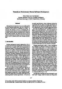
2.2.2 The Component-Based Development Process The specific aspect of developing software consistent with the CBSE principles is based on a strict separation between component development and system development (with components). Both processes can follow the traditional “Requirement, Specification, Implementation, and Verification” phases whether, for instance, in a waterfall or V-model form. However, due to the presence of components characteristic features emerge. Both processes and their interaction are illustrated in Figure 2.1.
System Development
System Requirements
System Verification
System Decomposition
System Composition
Component Requirements
Component Verification
Component Assessment Component Identification
Release
Implementation Component Evaluation
Selection
Adaptation
Storage
or New Component Development
Requirements
Component Development
Specific Requirements
or
Release
Generic Requirements
Specification
Verification
Legend: Inquiry for pre-existing components
Implementation
Next step in the process
Figure 2.1: Component-based development process overview. Starting normally with an elicitation of system requirements, the system development takes immediately advantage of the presence of previously developed components which are stored in a component repository. Based on the knowledge and identification of a set of component candidates that potentially fit the requirements, system requirements are broken down into component
2.2 Component-Based Software Engineering
19
requirements and accordingly, a system specification is built with its corresponding component specifications. Whereas the components that do not completely fit the specifics of the current design are adapted, the requirements and specification of the non-already implemented components are forwarded to the component development process to be developed. Once all components have been implemented and individually tested against their requirements, they are integrated together to form the final system. This integration is then verified and validated against the system requirements, both with regards to functional and extra-functional aspects. As for the component development process, the steps are generally quite comparable to the ones found in traditional software development. Based on requirements and specification coming from system development, components are implemented and tested against these requirements. When the components meet their individual requirements, they are then delivered to be integrated during the system development and/or stored in repository as candidate for future reuse. However the component development process also aims at building components satisfying requirements not issued from system development but extracted to realize more generic components that can be used in many different contexts. This way of developing component is more difficult since it requires to envisage all possible contexts in which the component will be used. This generates components that are bigger than custom-made components since they need to fit more usage contexts. This introduces challenges for embedded system development since it requires efficient components.
2.2.3 Component-Based Software Engineering for Embedded System Development Contrary to other domains in which component-based software engineering have proven to be successfully used for common software development (desktop, business, internet or entertainment applications), CBSE has still difficulties to really breakthrough for the development of embedded systems. Indeed, most of the existing general-purpose component technologies have been developed with little consideration to factors that are of high important for embedded systems such as their resource limitations, timing properties or safety-criticality. The mismatch between the requirements for developing traditional PC applications and the ones for embedded systems hinder a straightforward transfer of these component-based technologies from one domain to another. In particular, the widespread component technologies such as EJB [27], .NET [26], COM [24] or CCM [25] do not sufficiently address these fundamental require-
20
Chapter 2. Background
ments and as a result are not that suitable for embedded systems development. They present some major drawbacks in being heavyweight, complex and generating some significant overhead on the target platform. As a consequence and as pointed in [29], there is still no widely used component technology standard really suitable for embedded systems. However, the principles and promising advantages brought out by CBSE have drawn a general attention towards fostering the use of component models for embedded system development. Several recent initiatives to provide standards based on component-based principles as well as the elaboration in the recent years of a number of component models dedicated to embedded systems reflect such a change. Some of these dedicated component models are KOALA [10], RUBUS [9], BlueArX [6, 7], SaveCCM [8], IEC-61131 [21] and AUTOSAR [5]. More details about these component models can be found in Paper A.
Chapter 3
Research Summary In this chapter, we describe the research performed. We first state the problem that this thesis addresses, then formulate the research questions, summarize the research results which contribute to answering those research questions, and present the used research methodology.
3.1 Problem Positioning Facing a growing demand to integrate more and more software functionalities, the traditional development methods for embedded systems are showing their limits. They have difficulty to efficiently cope with the resulting problems, namely increasing complexity, distribution, stringent resource limitations, a strong coupling between software and hardware, timing properties, safety-critical issues, etc. An important challenge is thus to propose development methods supporting those new requirements to facilitate embedded software development and ensure the quality and the dependability of the delivered products. Motivated by the need for solutions, the main challenge that this thesis aims at addressing can be formulated by the following question: How can distributed embedded systems be developed in a predictable and efficient way while following the CBSE principles? Otherwise stated, this means that this thesis aims at clarifying what are the important characteristics that the development of embedded systems requires and 21
22
Chapter 3. Research Summary
determining how to adapt the prerequisite of CBSE to suitably handle these characteristics. In particular, this can be seen as developing a suitable component technology which aims at providing support to address the embedded system requirements. Therefore the main research objective of this thesis is to propose concepts, approaches, and techniques concerned with the elaboration of an efficient component-based software development for distributed embedded systems, covering the development process stages (from early design to system deployment and synthesis) as well as enabling reusability and various types of analysis. It also looks at determining the needed engineering practices and tools to support the theories which have been proposed. However, this thesis is not interested in distribution primarily, and does not aim at providing new distribution architecture or communication protocols. Distribution is only considered for the sole purpose that subsystems can be distributed across the architecture and communicate through dedicated networks, as is the case in the vehicular domain for instance. Besides, other factors, outside the scope of this thesis, need also to be investigated to foster the usage of CBD and improve its efficiency for embedded system development. This is the case of development processes, businesses processes, or devising suitable analysis theories complying with the componentbased theories. The problem envisaged in this thesis is quite broad. In order to reduce its scope, we have worked under assumptions issued from a previous work done at MDH on the SaveCCT development approach ([8], [30]). This work has shown the value of having a restricted component model to help in the analysability of the system already in the design phase. Accordingly, we have considered the following research assumptions: – A specific component model for distributed embedded system, with a precise semantic is needed;
– Composition theories alone are not enough and require the existence of technologies which include appropriate tool support;
– Introducing verification of extra-functional properties in the early phases of the development process is necessary.
3.2 Research Questions
23
3.2 Research Questions In order to reduce the scope of the research and define a direction to provide answers to it, three research questions, hereafter described, are stated. The answers to these research questions will unveil important aspects contributing to answering the main question. Research question 1 What are the suitable characteristics of a component model to efficiently support software design of distributed embedded systems? Through this research question, the purpose is (i) to explore and identify important needs in the development of distributed embedded systems, focusing more specifically on the design phase while keeping in mind that a componentbased approach is intended, and (ii) to adapt an existing (or propose a new) component model with suitable characteristics, properties and features to provide a solution to these needs. In order to provide an answer to this question, we first study the development process of distributed embedded-systems with the aim to identify concerns that need to be addressed by the component model. The second step is to investigate which kinds of component models exist nowadays, what their characteristics and their domain of applicability are, and if they can be used in the context of this research. Finally, based on the previous results and the work assumptions, the decision of adapting an existing component model or proposing a new one has to be taken. Research question 2 How to provide efficient integration support for management of functional and extra-functional properties within a component model? This research question aims mainly at the predictability aspect needed in the development of distributed embedded systems in order to provide the necessary quality of the system to be developed. In that respect, this research question focuses on determining a way to enhance the component model to provide the necessary grounds to efficiently support the analysis of important properties. Since various types of information need to be created and used as a basis for taking decision and/or analysing the system under development, it is important to have means to identify, specify, and locate these pieces of information.
24
Chapter 3. Research Summary
To answer this research question, we have (i) identified and described a set of properties which are suitable in the context of the development of distributed embedded systems; (ii) identified to what component model entities (components, interfaces, bindings, etc.) those properties relate; (iii) enhanced the proposed component model to support the management of those properties. Research question 3 How to build an integrated development environment encapsulating suitable models and technologies to efficiently support component-based development of software for embedded systems? This research question addresses the practical needs required to efficiently support the development of embedded systems. With this research question, the main goal is to develop a prototype and evaluate the feasibility of the approach.
3.3 Research Contribution The contribution presented in this thesis is the outcome of a set of results contributing in the elaboration of efficient component-based software development enabling the development of predictable distributed embedded systems. In this respect, the contributions of this thesis are the following: – a classification framework for component models; – requirements for a domain specific component-based approach for embedded systems; – a component model for distributed embedded systems; – a method to integrate and manage extra-functional properties within component models; and – a prototype implementation of an integrated development environment that implements the overall approach. Figure 3.1 illustrates how these research results fit together to form the overall contribution of this thesis. Through literature surveys and interviews, challenges and needs in the current development methods for embedded systems (Paper B) as well as requirements for merging of CBSE principles with embedded systems development (Paper A and B) have been explored. Based
3.3 Research Contribution
25
Problem Formulation and Surveys Component Model Classification (Paper A)
ES Development Needs (Paper B)
Proposed Methods Component-Based Approach (Paper B)
Component Model (Paper C)
EFP Management (Paper D)
Implementation Demonstrator Application (Paper E)
Legend:
influences
Figure 3.1: Relations between the contributions. on the findings, several methods to improve the component-based software development for distributed embedded systems have been proposed (Paper B, C and D). Meanwhile, a prototype implementation (Paper E) based on a SaveCCT has been developed to demonstrate the feasibility, advantages and drawbacks of combining CBSE design with various analysis and deployment techniques to produce embedded systems. The work on this prototype implementation has also influenced the proposed methods. Next, a brief overview of these research results is given. More details can be found in the included papers in the second part of this thesis.
3.3.1 A Classification Framework for Component Models The idea behind the elaboration of the component model classification framework is to study component-based software engineering state-of-the-art to extract the key principles of the area and analyse their integration within existing component models. Through the utilisation of this framework, principal similitudes and differences between component models can be identified as well as their conformance to the CBSE basic principles. After a thorough study of CBSE state-of-the-art including many component model descriptions and existing classifications of component models, architec-
26
Chapter 3. Research Summary
ture description languages and quality attributes, the following four dimensions have been chosen as main criteria to describe different facets of component models: 1. Lifecycle, which identifies the support provided (explicitly or implicitly) by the component models, in certain points of the lifecycle of components. 2. Constructs, which identifies (i) the component interface used for the interaction with other components and external environment, (ii) the means of component binding and, (iii) the interaction capabilities. 3. Extra-functional properties, which identifies specifications of different property values, and means for their management and composition. 4. Domains, which shows in which application and business domains the component models are used or supposed to be used. Each dimension has then been refined into several aspects and the framework has been populated with more than twenty component models from various domains. The overall classification scheme as well as more details concerning the classification framework can be found in Paper A. In addition to allow performing a raw comparison between component models by identifying their common characteristics and differences, such a classification framework can also be used for other purposes. In particular, it can serve as a basis to select a component model according to criteria such as the presence of a support for a specific extra-functional property, its implementation language or the support for all the development phases. Ultimately, it could also help in the convergence towards a standardization of main characteristics of component models. The use of the classification framework in the context of this thesis constitutes the first step towards the identification of suitable characteristics of component models dedicated to embedded system development and a support to eventually determine if an already existing component model could be reused. From the analysis of the classification framework with regards to component models dedicated to embedded systems development, the following characteristics can be extracted as suitable for component models for embedded systems (assuming that the majority is always right). – communication style: synchronous pipe & filter – implementation language: C (or C++)
3.3 Research Contribution
27
In comparison to general purpose component models, dedicated component models are more concerned with dealing with extra-functional properties and provide support to manage certain type of properties (often timing and resource usage).
3.3.2 Requirements for a Component-Based Approach Based on an evaluation of embedded system requirements and their development needs, the main objective with this work is to (i) establish concepts and requirements suitable for a component-based approach for distributed embedded systems, and (ii) characterise the component model underlying it. As pointed out in Section 2, a key characteristic of embedded system development is the importance of producing reliable embedded systems in an efficient way. In our view, this requires the provision of a fully integrated approach managing traceability and dependencies between the artefacts generated during the development process such as source code files, models of entities, analysis results, design variants, etc. as well as providing means for various analysis techniques throughout the whole development process. Following this standpoint, a suitable component-based approach for distributed embedded systems (see Paper B) should cover the whole development process starting from a vague specification of the system based on early requirements up to its final and precise specification and implementation ready to be synthesized and deployed. It should also be centered around a unified notion of components as a first-class entity gathering requirements, documentation, source code, various models, predicted and experimentally measured values, etc. and, (iii) improve the predictability of the developed systems by easily enabling various types of analysis, storing and managing the artefacts needed and/or produced by these analysis throughout the development process. Merging embedded system requirements with a holistic component-based approach throughout the whole development raises the need to cope simultaneously with: – the coexistence of different abstraction levels, – the different concerns at different granularity levels, – platform dependence, – the need to integrate various analysis techniques throughout the whole development, and – the need to foster reuse.
28
Chapter 3. Research Summary
big
Our solution to address these different concerns lays in a conceptual component model composed of two dimensions. The first dimension is the abstraction level (the abstract-to-concrete scale in Figure 3.2), which describes the successive refinement from a rough sketch of a component to its final realisation consisting of source code, detailed timing and resource models for instance. The second dimension expresses the granularity level, i.e. the complexity and size of the components to realise, and is represented by the bigto-small scale in Figure 3.2. For example, an anti-lock braking system (ABS) that constantly adapts the brake pressure in accordance with the wheel speed to prevent wheel skidding while braking belongs to the big part of the scale. On the other hand, a brake force controller which task is only to monitor and adjust the pressure in a brake belongs to the small part of the scale. As illustrated in Figure 3.2, a component can be in different abstraction levels.
� � ���������
� �� ����� ����������
�
���� ��
������� �
Figure 3.2: Proposed conceptual component model.
This work has set the conceptual foundations which guided us towards the elaboration of ProCom, the component model for control-intensive distributed embedded systems described briefly in the next section.
3.3 Research Contribution
29
3.3.3 The ProCom Component Model With this work, the aim is to specify a component model dedicated to the development of control-intensive distributed embedded systems for the vehicular and automation domains primarily. This component model is intended to provide the cornerstone of the integrated component-based approach described in Section 3.3.2 and therefore must address the concerns identified above. Taking these concerns into account, the ProCom component model has been developed. To address the first concern, namely the different abstraction levels, ProCom proposes to specify components as black boxes in the early design stage. In this particular case, a black box component is a component with its internal content is hidden because it has not been decided yet. During the development, it can be decided that the component will be a composite component built out of subcomponents or a primitive component realized through source code. This means that information is gradually associated with the component, including adding detailed models for specifying its internal structure, its behaviour, its resource usage and finally, with the provision of its source code, the component is transformed from a abstract black box component to a concrete component. In that sense, components are viewed as units of design, implementation and reuse. They can be developed independently, stored in repositories and reused in multiple applications. To that purpose, ProCom is centered around a unified notion for components which are considered as a collection gathering all the information needed and/or specified at different points of time of the development process. The different concerns that exist at different levels of granularity is addressed through a partitioning of ProCom in two distinct layers of hierarchical component models. In addition to propose different support to handle these different concerns, the layers differ in terms of architectural styles and associated semantics for the components. The upper layer, called ProSys, is intended to design a system as a collection of communicating subsystems executing concurrently and possibly distributed. In that layer, the subsystems are the components of the model and they communicate together through asynchronous message passing between typed message ports. This communication style is suitable at this level of granularity, since it allows transparent communication between subsystems independently of their location on the same physical node or not.
30
Chapter 3. Research Summary
In comparison, the lower layer, called ProSave, is used for detailed modelling of small parts of control functionality of subsystems allocated to a single node and interacting with the system environment through sensors and actuators. Building on the approved features for analysability of SaveCCM [30, 31], the “pipe and filter” paradigm as well as a restrictive semantics have been adopted for this layer. The only architectural entities are components as main abstraction for real-time tasks or control functions and connectors for special operations on the connection between the components. The two layers are not independent but relate to each other, since ProSys component may be modelled out of ProSave components. For more detailed information about ProCom, the reader is referred to Paper C or [32].
3.3.4 Integration of Extra-Functional Properties in Component Models As identified in Section 3.3.2, an important requirement in the development of embedded systems is the possibility to perform various types of analysis throughout the whole development starting from early analysis to more detailed analysis and verification later. To efficiently contribute to the development, these analysis techniques must be an intrinsic part of the approach and be tightly connected to the component model whenever this is possible. This implies that all the artefacts needed and produced by the analysis techniques should be easily accessible, refer to the appropriate entities of the component model and be managed in a systematic way to eventually automate the analysis. Additionally, the analysis results should be reused in a suitable way. In this respect, this work proposes a way to specify, integrate and manage information within component models, and more specifically extra-functional properties. This work constitutes the second step towards conciliating analysis with the envisaged component-based approach, after having specified a component model with a restrictive semantics and limited number of architectural elements. The main purpose with this works is to provide an appropriate support allowing a closer integration of analysis with the component model, with the long-term vision of eventually enabling as many fully automated analysis and verification steps as possible. To this end, this work started by looking at the huge diversity of extrafunctional properties that can be defined and accordingly proposes a format for their specification in order to manage them in a systematic way. The main intention with this definition is to have an unambiguous and precise semantics both with respect to the meaning of the extra-functional property and to the
3.3 Research Contribution
31
correct format for specifying value. Thus, through the concept of Attribute, we define an extra-functional property as follows: Attribute
=
TypeIdentifier, Value+
�
Value = hData, Metadata, ValidityCondition∗ i where: – TypeIdentifier defines the extra-functional property in a unique and unambiguous way; – Data contains the concrete value for the property; – Metadata provides complementary information on data and allows to distinguish between them; and – ValidityConditions describe the conditions under which the value is valid. This definition implies that an attribute, i.e. an extra-functional property, can have multiple values identified by metadata or the conditions under which the values have been obtained, such as for instance some assumptions on the target platform specification. This particularity of our definition has emerged from the need to cover both the entire development process from early design up to synthesis and deployment phases and the relation with the target platform specification. More explanations concerning the terms used in this definition as well as discussion about multiple values and reusability of extra-functional properties can be found in Paper D. In addition, techniques outside this definition are provided to ensure a systematic comprehension and utilisation of the attribute concept within a development context: – Connection, through an extension of the metamodel, to the entities of the component model that can have attributes. – Definition of an attribute registry to ensure the uniqueness of the attribute specification. – Specification of composition and selection techniques.
32
Chapter 3. Research Summary
3.3.5 Prototype Implementation The main intention with this work is to evaluate from a practical angle the envisaged approach of merging component-based principles and embedded system development needs i.e. to establish the advantages, drawbacks and limitations of the approach. This requires an implementation of the complete development toolchain from design up to synthesis and deployment, including some analysis techniques. As the work on establishing the requirements for the elaboration of ProCom was still in its early phase, no analysis or synthesis techniques were available at the start of this research work. Instead, it has been decided to use the concepts, methods and techniques developed for SaveCCT [33] to develop a first prototype, since SaveCCT shares many similarities with the work presented in this thesis. In particular, it presents a simple use-case scenario of the envisaged approach in that sense that the use of component is restricted to the design only and the analysis is performed on system-scale. Component-Based Design Architectural Model
Synthesis (automated transformations)
Validation & Verification (timing/safety/ reachability)
Early Formal Analysis Analysis Models
Deployment Executable System
Figure 3.3: Overview of the SaveCCT approach. Based on [8] and with respect to the SaveCCM reference manual [33] which defines the exchange format to be used between the tools, an integrated development environment, called Save-IDE, has been specified and developed. Compared to the majority of existing IDEs which focus mainly on programming aspects, the Save-IDE integrates the design, analysis, transformation, verification and synthesis activities as illustrated in Figure 3.3. These activities are supported by a set of dedicated tools. The complete description of the approach and the environment can be found in Paper E.
3.4 Methodology
33
3.4 Methodology Equally important as the proposed solutions to answer the research questions, is to adopt an appropriate research methodology helping guarantee the soundness and the reproducibility of the work. In this thesis, we followed a methodology adapted from the guidelines proposed by Shaw in [34] to perform good software engineering research. This approach starts with the identification of a problem from the real world (Problem Identification), in our case the limitations of the current development methods for distributed embedded systems due to the increasing complexity of new embedded system functionalities. The problem is then transferred into a research setting to be investigated with the prospects of findings solutions to it. However, since real world problems are generally quite complex, the scope of the problem needs first to be restricted to be manageable within a research context (Problem Setting). This limitation made us focus on a particular aspect of the real problem by formulating the research problem that will be addressed within the work (Problem Formulation), and then by stating Working Assumptions and Research Questions, which together set a frame for the work. Similarly to passing from a real world problem to a research problem, breaking down the research problem into a set of research questions narrows down even further the problem to investigate and helps on focusing on particular aspects of the research problem. In that sense, the working assumptions provide a starting point to the work whereas the research questions correspond more to the specification of the angle of attack chosen to investigate the research problem. Once the problem to address is clearly defined, the research work starts with the study of related theories, methods, approaches, techniques or solutions that have already been performed on the topic (Background Theories). With the knowledge of the existing state-of-the-art and the questions to answer, some solutions can be devised (Solutions). Formulating solutions is not a straightforward process but an iterative one, in which preliminary ideas are formulated, worked out, refined or even sometimes left aside. When the ideas are mature enough, they must be evaluated and validated to check whether they really answer the research question in a suitable way (Validation). If this step fails, the proposed solutions need again to be revisited, refined, improved or thrown away. In that sense, this is an iterative trial and error process, in which analysing the causes of the erroneous solutions might provide useful inputs to find new, better or simply working solutions. After the validation step is satisfied, the applicability of the proposed solutions to solve the real-world problem can be evaluated (Evaluation). An
34
Chapter 3. Research Summary
Real-World Context
Problem Identification
Research Context Problem Setting Problem Formulation
Work Assumptions
Research Questions
Research Work Background Theories Applicability Evaluation
Solutions
Validation
Figure 3.4: Overview of the applied research process.
overview of this approach is given in Figure 3.4. The work presented in this thesis is concerned with the problem identification, problem setting and research work steps. The validation and evaluation steps remains as future work. Each research questions can be answered in different ways and in applying different approaches, thus we describe below the methodology that has been used in the research work described in the previous sections. The process to answer the first research question started by studying both the needs in the development process of distributed embedded systems and the current state-of-the-art of component-based software engineering focusing on existing component models, in particular SaveCCM [8]. This study was based on literature surveys and discussions with domain experts of vehicular and automation domains. Based on these findings, requirements for the component model were extracted and served as foundations in the elaboration of ProCom, which addresses some of the limitations of SaveCCM. As for the work concerned which research question 2, it also started with a literature surveys on extra-functional properties and their management and the identification of a few properties of interest in the development process. Then
3.4 Methodology
35
we have tried to relate their management to their utilisation within the development process. The methodology followed here was iterative and started with the development of a prototype implementing some preliminary ideas to get a better understanding of their integrations and contributions in the development process. This preliminary solutions has then been refined into the attribute framework presented in Paper D. The last research question was concerned with the feasibility of combining a component-based approach with formal early analysis. We proceeded by construction and realisation of an integrated development environment that provided us useful lessons learned.
Chapter 4
Related Work In this chapter, we relate the contributions presented in this thesis, namely a new component model for distributed embedded systems, a framework to manage extra-functional properties and an integrated development environment, to similar relevant approaches.
4.1 Component Models A broad range of component models exists nowadays, either general purpose or dedicated component models, as compiled in various classifications (as in [4] or [35] for instance). However few component models actually target the development of embedded systems and most of them focus on a specific domain only. Using the component models detailed in Paper A as a basis, this section goes back over the component models targeting embedded systems and compares them with the component model proposed in this thesis. In the automotive domain, the AUTOSAR (AUTomotive Open System ARchitecture) consortium [1] is the first large-scaled initiative to gather manufacturers, suppliers and tool developers from the automotive field to establish an open and standardised software architecture for the automotive domain enabling component-based software design modelling. Through this common standard, the vision of AUTOSAR is to facilitate the exchange of solutions (including software components) between different vehicle platforms and subsystem manufacturers as well as between vehicle product lines. In that sense, AUTOSAR targets the upper part of the granularity scale of the proposed 37
38
Chapter 4. Related Work
conceptual component model. Similar to our approach, AUTOSAR relies upon the use of a component-based software design model. However the two approaches have principal differences. In particular, AUTOSAR component model proposes both pipe and filter and client-server paradigms communicating transparently across the architecture through the use of standardised interfaces. Although targeting development of applications for the automotive domain, AUTOSAR in its current version lacks support to express and analyse extra-functional properties in particular timing properties as for instance worstcase execution time or end-to-end deadline. An upcoming release AUTOSAR 4.0, done in cooperation with the TIMMO project [36] and EAST-ADL [37], intends to tackle this lack by an extension of the current metamodel. In particular, the TIMMO project intends to propose a standardised infrastructure to manage timing properties and enable their analysis at all abstraction levels from early design to deployment. A second initiative that shows the growing interest from the automotive domain in component-based software development comes from Bosch with BlueArX [6, 38]. Also based on a design-time component model, BlueArX differentiates itself from AUTOSAR in supporting timing and other non functional requirements as well as in focusing on complete development process for single ECUs. To this respect, BlueArX is relatively close to the objectives and contributions presented in this thesis in particular with regards to the lower layer of the component model (ProSave). However differences exist. First, through the ProSys layer of the component model, ProCom intends to support also the development of embedded software systems distributed across several ECUs. Another difference lays in the proposed support to integrate analysis. Whereas extra-functional properties can be associated with any entities of the ProCom component model (components, ports, services, connections or component instances) through the attribute framework extension, BlueArX on the other hand endows components with an additional analytical interface to perform analysis either at system- or component-scale. In a recent work [7], BlueArX has been extended to support the analysis of timing properties in relation to operational mode, a feature which is not supported yet within ProCom. Developed in a close cooperation between Arcticus Systems AB and M¨alardalen University, the Rubus Component Technology [9] is another example of an industrial use of component-based approach in the vehicular domain. Similarly to ProCom, the RUBUS component model focuses on expressivity and analysability through a restrictive component model. However, the Rubus component model allows the specification of timing properties only and is not primarily concerned with reuse.
4.1 Component Models
39
The contributions found in this thesis are largely inspired by previous work done at M¨alardalen University on the elaboration of a component model for vehicular domain. SaveCCM [33] is a design-time component model consisting of a few design entities with a restrictive “Read-Execute-Write” execution semantics and communicating through a “pipe & filter” paradigm in which the control- and data-flows are distinctly separated. Having such a restrictive semantics, it enables formal validation and verification of the system already in early phase of the development process, prior any implementation as well as automated part of the transformations into an executable system as explained in [39]. ProCom is built on the knowledge and experiment gained from the development of SaveCCM and tries to alleviate some of the restrictions and drawbacks of SaveCCM in particular in strengthening the concept of components, considering distribution and handling functional and extra-functional properties in a more systematic way. Whereas the ProSave layer is to a large extent directly inspired from SaveCCM, the upper layer (ProSys) aims at addressing the distribution of subsystems, which was not addressed within SaveCCM. In the field of consumer electronics, Philips has developed and successfully used the Koala component model [10] for the production of various consumer electronic product families (TV, DVD, etc.). In comparison to the aforementioned initiatives, Koala is less oriented towards safety-critical applications than what exists in the automotive domain for example. However, as Koala still targets severely constrained embedded systems, it pays a special attention to static resource usage, such as static memory for instance, but it lacks support for managing other extra-functional properties. The dependencies between properties are handled through diversity spreadsheet, which is a mechanism outside the component. Koala has served as input in the Robocop [40] project done in collaboration between Philips and Eindhoven Technical University. Similarly to ProCom, Robocop considers components as a collection of models covering the different aspects of the development process. Models are also used to manage extra-functional properties as for instance the resource model, which describes the resource consumption of components in terms of mathematical cost functions, or the behavioural model, which specifies the sequence in which the operations of the component must be invoked. Additional models can be created. Pecos [41] is a joined project between ABB Corporate Research and Bern University. Its goal is to provide an environment that supports specification, composition, configuration checking and deployment for a specific type of reactive embedded systems (field devices) built from software components. Contrary to ProCom for which the components of each layer have their own
40
Chapter 4. Related Work
execution semantics, i.e. ProSys components are active whereas ProSave components are passive, the two types are put together in Pecos. Also, since components in Pecos have only data ports, there is a need for an additional type of component, called event component, which activation is triggered by the arrival of an event. With regards to extra-functional properties, Pecos enables the specification in a name-value pair format in order to investigate the prediction of the timing and memory usage of embedded systems. However, this specification is limited to name-value pairs in difference to the possibility offered to specify extra-functional properties in ProCom. Pin [42], a component model developed at Carnegie Mellon Software Engineering Institute (SEI), serves as basis for the prediction-enabled component technologies (PECTs) which aims at attaining predictability of run-time properties such as performance, safety and security. Alike our approach, PECT stresses the importance of providing suitable quality prediction based on analysis theories. However the methods to integrate analysis differ. Whereas ProCom relies on an external attribute framework as means to handle functional and extra-functional properties resulting from different analysis techniques, PECT is centered around a reasoning framework consisting of analytical interfaces used to specify specific properties, and corresponding analysis theories to enable the prediction of these properties. Also in comparison to ProCom, Pin is a flat component model which does not support distribution.
4.2 Alternative Approaches This section correlates our work with other approaches that are not primarily concerned with the principles and methods advocated in CBSE but are still intended to support the development of distributed embedded systems. In the automation domain, the standards IEC-61131 [21] and its successor IEC-61499 [43] proposed by the International Electrotechnical Commission are well established technologies for the design of Programmable Logic Controllers. Whereas IEC-61131 allows to graphically compose systems out of function blocks, IEC-61499 has been developed to enforce encapsulation and provide a support for distribution. From a design perspective, ProCom shares some similarities with these graphical languages, in particular the encapsulated entities communicating with a “pipe & filter” paradigm with explicit separation between data- and control-flow, and the distribution support. However the semantics associated with the function blocks are weaker compared to the ProCom components, and the standards lack support for specifying and managing
4.2 Alternative Approaches
41
extra-functional properties and their analysis. This holds back the possibility for formal analysis of the systems under development, which is one of the major objectives this thesis aims at. In the automotive domain, alike ProCom, EAST-ADL (Electronic Architecture and Software Technology – Architecture Description Language) [37] aims at providing a support for the complete development of distributed embedded systems by taking into consideration the hardware, software and environment development assets. Although both approaches share similar objectives, they differ in they way those objectives are approached. Whereas ProCom emphases components as assets for capturing development information thus aiming at reusability, EAST-ADL focuses on architecture description to structure it. In EAST-ADL information is structured into five abstraction levels, which describe the functionalities from several standpoints. Each entity of a level realizes the entities of the higher abstraction levels. ProCom covers three of these levels (analysis level, design level and implementation level), and leaves out the electronic feature design (vehicle level) and the support for the deployment of the final binary (operational level). Similarly to ProCom, EAST-ADL also supports modelling of non-structural aspects such as behavioural description but covers in addition validation and verification activities as well as management of requirements. EAST-ADL was originally developed as an EAST-EEA ITEA project involving car manufacturers and suppliers and now it is refined as a part of ATESST project to be aligned with the major standardization efforts existing in the automotive and real-time domains (AUTOSAR, MARTE, and SysML). The Architecture and Analysis Description Language (AADL) [44], formerly known as Avionics Architecture Description Language, is a standardization effort led by the Society of Automotive Engineers (SAE) to provide support for the development of real-time and safety-critical embedded systems for aerospace, avionics, robotic and automotive domains. Consequently, AADL stresses the importance of analysis to meet the particular constraints and requirements of the envisaged target domains. It provides a formal hierarchical description of the systems including properties to support the use of various formal analysis techniques related to timing, resources, safety and reliability with the aim of validating, verifying and performing tradeoff analysis of the system. Properties are defined as a triple (Name, Type, Value) that can be attached to different entities and can have specific instance values. To this respect, AADL is comparable to ProCom and its attribute framework. However, in comparison to ProCom, AADL is “only” a description language and does not provide links to design and implementation technologies. In that sense, it
42
Chapter 4. Related Work
decomposes the system in a top-down manner specifying entities and how they interact and are integrated together without providing any implementation details. Thus AADL is not primarily concerned with reusability issues. On the other hand, AADL includes some features that could be interesting to take into consideration in the further development of ProCom such as the specification of execution platforms and operational modes. Other approaches applies Model-Driven Engineering (MDE) techniques that allow to automate the development process in relying on models as primary development artefacts, hence abstracting away from implementation concerns. These models are intended to serve as input to automatically derive implementation, documentation, test cases, and much more. Although not limited to UML-based models, the attractiveness of these approaches has increased since the introduction of UML 2.0 [45] and various UML-profiles such as SysML [46] and MARTE [47]. In particular MARTE, the successor of the scheduling, performance and timing (SPT) profile, defines a set of basic concepts for model-driven development of real-time embedded systems. In that sense, MARTE is closely related to the work presented in this thesis, especially with the specification of extra-functional properties including time and resources and the intention to support various types of model-based analysis such as schedulability and performance. In addition, through the General Component Model sub-profile, MARTE proposes support for CBSE. However contrasting to our work, MARTE does not focus on implementation and reuse.
4.3 Integrated Development Environment Integrated Development Environments (IDEs) are not new. They traditionally provide dedicated support for developing applications in various programming languages such as Pascal, C/C++, Java, PhP among many others. In these environments, the main focus is oriented towards the implementation phase of the development process, which means that typically source code editors (with syntax highlighting, auto-completion, bracket matching, etc.), compiler and/or interpreters, and debuggers are supplied to the developers. For object-oriented software development, class browsers, object inspectors, and class hierarchy diagrams, are also integrated. The most common representatives of these IDEs include Delphi [48], Eclipse [49], and Microsoft Visual Studio [50]. As for CBSE, the environments are generally tightly centered around a component model, and focus on specific development phases (implementation) and domain. Some examples of such environment are Palladio Component Model tool [51], Koala Development Tools, Netbeans [52] for EJB and Jav-
4.3 Integrated Development Environment
43
aBeans. However for the development of safety-critical real-time embedded systems, environments providing more verification and simulation capabilities are often used instead — either a UML-based environment or a dedicated environment. In those environments, code generation is a rather common feature, which allows to automatically derive accurate implementation from models. In some cases, as for BridgePoint [53], the generated implementation can be executed directly to simulate the behaviour of the system. UML-based environments propose to develop a system in starting by its design following UML or a UML-profile. Typically, those environments cover design, code generation, execution, tests, and simulation. Despite the recent initiatives of SPT, SysML and MARTE to incorporate extra-functional properties into UML, few tools actually support those new standards and when this support exists, it still lacks formal grounds. As a result no automatic verification is available in those environments. However, through combining UML class diagrams and UML behaviour diagrams, the Fujaba Tool Suite [54] manages to enable formal system design that can be used to generate Java source code. Rational Rose Technical Developer [55], Rhapsody [56] and BridgePoint are some examples of environments belonging to this category. On the other hand, dedicated integrated development environments are centered around a dedicated modelling language. Simulink [57], from MathWorks, is the leader environment to model, simulate, implement and analyze dynamic and embedded systems. It is mainly used in control theory and digital signal processing for designing the applications together with modelling its environment. Once the system is designed out of block diagrams (very similar to components), the system can be synthesized into executable code through a connection to the Real-Time Workshop tool also developed by MathWorks. A repository support is provided on the form of building block libraries, from which building blocks are picked and customized to fit the needs of the new design. Simulink is integrated with Matlab, hence allowing algorithm development, data visualization, data analysis, and numeric computation. Other major dedicated environment is SCADE [58], which proposes an environment to produce mission and safety-critical systems mainly for aerospace, defence and automotive domains. SCADE is endowed with the following features: graphical and textual editors, simulator, formal proof (Design Verifier), code generators, model test coverage and can be connected to Simulink, DOORS, Altia, UML/SysML, etc. Save-IDE, described in Paper E, also belongs to this category. In comparison to the other environments, Fujaba Tool Suite excepted, Save-IDE provides
44
Chapter 4. Related Work
an environment allowing formal modelling of a system fully compliant with the SaveCCM semantics, hence enabling formal verification of the behaviour of the system with respect to time, safety and reachability properties. However, in order to benefit from the large variety of existing tools for UML, Save-IDE through its SaveUML extension [59] allows transforming a SaveCCM design into a UML-profile and vice-versa.
Chapter 5
Conclusions and Future Work We have described in this thesis a possible approach to merge component-based software engineering principles with the specifics of distributed embedded systems with the aim of providing solutions towards an efficient development environment. This approach is based on a dedicated component model tailored to fit the embedded system development needs. In particular it provides a restricted semantics to facilitate the analysability of the system being designed and a dedicated (extra-) functional properties framework to ease the integration and management of analysis techniques and their outputs. This chapter concludes the thesis by reviewing and discussing its contributions with regards to the research questions stated in Chapter 3, and by providing directions for future work.
5.1 Discussions Clearly, the objective of proposing integrated solutions to develop distributed embedded systems in a predictable and efficient way while following the CBSE principles is ambitious. It can be addressed in many different ways and requires many fragmentary results which need to tightly fit together. This objective is not attained entirely through the contributions presented within this thesis since the work is not completed yet. However, we have provided basic foundations and directions, which hopefully contribute to move closer to its realisation. 45
46
Chapter 5. Conclusions and Future Work
The main piece of remaining work concerns the validation and evaluation of the proposed methods, in particular with respect to the envisaged componentbased approach and its underlying component model and extra-functional property support. Indeed, no validation or evaluation in an industrial context has been performed yet and this constitutes an important part of future work that remains to be done. As a consequence, the answers to the research questions 1 and 2 provided below correspond more to initial findings on the subject than fully accepted results corroborated through the development of suitable applications or even industrial case-studies. The remainder of this section provides answers to the research questions introduced in Section 3.2 and discussions on their relevance. Research Question 1: What are the suitable characteristics of a component model to efficiently support software design of distributed embedded systems? Based on an analysis of the component model classification framework and an evaluation of the requirements for embedded system development, a number of characteristics that seem suitable for component-based embedded system development and its associated component model have been identified and detailed in Paper B and integrated in ProCom (Paper C). As our answer to the Research Question 1, yet to be confirmed by experiments or case-studies, a component model should support: – Different abstraction levels (i.e. the coexistence of components in an early design phase and fully realised components). – The different concerns that exist at different granularity levels (i.e. an high-level view of loosely coupled complex subsystems together with a low-level view of small non-distributed functionalities similar to control loops). – Platform awareness while still being platform independent. – Various analysis techniques. In addition, as identified in [30] for the development of embedded control software, the component model semantics should also be limited and restrictive to support important extra-functional properties such as timing, safety or reliability. With regards to efficiency of software development, this implies finding the appropriate tradeoff between flexibility on one hand and analysability and predictability on the other hand. We approached this problem by alleviating some
5.1 Discussions
47
of the restrictions present in SaveCCM — in particular for the ProSys level which requires more flexibility than ProSave since it deals with distributed active subsystems executing concurrently — while reinforcing the concept of components as a unified notion throughout the development process. In spite of this, ProCom provides a semantics precise enough to be formally expressed through timed finite state machines as demonstrated in [60]. Similar to what has been done in SaveCCM, this should permit an automated integration of formal analysis tools, improving the development process performance. The strong coupling between target platform specification and software implementation is an important challenge which requires to be addressed in a suitable way since the correctness of analysis results and values of extrafunctional properties strongly depend upon the target platform specification and the deployment configuration. Postponing the access to this information to a late development stage could result in incorrect design and implementation of the system to be executed, leading to an eventual costly redesign and re-implementation of the erroneous parts of the system. Yet, breaking the hardware abstraction and making the target specification part of the component model is not a suitable solution since this would makes all components platform dependant and hinder their reusability breaking then one fundament of CBSE. An appropriate solution lays probably in between those two extreme solutions. Research Question 2: How to provide efficient integration support for management of functional and extra-functional properties within a component model? Answering this question corresponds to finding an appropriate way to specify, integrate and handle functional and extra-functional properties in a component model in a systematic way. Thus, we addressed this question through the approach briefly described in Section 3.3.4 and detailed in Paper D. This approach combines a model for specifying extra-functional properties with techniques outside this specification, such as a property registry and property selection, to ensure the correctness of their utilisation in the current development context. Remarkably, a distinctive feature of our model lays in its ability to handle the specification of multiple values for a property, where each value is identified through the provision of suitable metadata and/or the context under which the value has been obtained. This approach can also be used to integrate the specification of functional properties without hampering the utilisation of interfaces. In this context, functional properties do not refer
48
Chapter 5. Conclusions and Future Work
to interface specification of the operations handled by the components, but to the modelling of the behaviour of the components in a format suitable for analysis techniques such as timed automata model. By this means, our intention is to increase the analysability and predictability of component-based embedded systems, and enabling a seamless and uniform integration of existing analysis and predictions theories into component models. However this solution introduces complexity in the design process in several ways. In addition to the possibility to have multiple values assessed at different point of time or by different techniques, it also envisions delegating the declarations of needed properties to, for example, the developers of the analysis techniques who know best the types of information they need as input and that they produce as outputs. In the end this could result in an explosion of property definitions in the registry. A possible solution would be to rely on a standardized catalogue of properties similarly to what exists for units (SI), date and time representation (ISO 8601) or the standard for evaluation of software quality (ISO 9126). Our approach to integrate extra-functional properties in component models reveals a lot of information concerning the details of the implementation of the components. Although this is not a major issue for in-house development, it naturally becomes more problematic for its utilisation in the development of systems or components for which the implementation details must remain hidden such as COTS components since all the models that have served for analysis are packaged together with the components. A solution could be to provide mechanisms to identify and automatically remove confidential information when components are distributed to third parties. Research Question 3: How to build an integrated development environment encapsulating suitable models and technologies to efficiently support component-based development of software for embedded systems? Based on [8] and with respect to the SaveCCM reference manual [33] which defines the exchange format to be used between the tools, an integrated development environment, called Save-IDE, has been specified and developed. This environment has been used internally by the members involved in its realisation but also externally by students outside the projects to develop diverse small applications. In [61], a comparison between Save-IDE and a professional tool enhanced with a profile for SaveCCM has been performed. This experiment is performed on a small group of students concerns only the modelling aspect of
5.1 Discussions
49
the environment. Yet the students’ feedback show some indications that a dedicated design environment is more efficient than a general-purpose environment customized to fit a particular need. So as a part of the answer to the research question, a first important feature is the presence of dedicated modelling editors. The environment has also been used in [62] and in [39], in which an industrial control system and a simple truck application have been realized respectively. Those two examples show the feasibility of the integrated approach. In particular, they highlight the possibilities of tightly interconnecting design and formal analysis tools, which enable formal analysis of the on-going design already in an early design phase. From the development and internal use of this environment, several conclusions have been drawn, leading to some areas of improvement for the environment and some of them as served as basis in the on-going work to develop an integrated development environment supporting the component-based approach presented in this thesis. These conclusions are other parts of our answer to this research question. The first conclusion is that components must be the main unit of development, similar to the concept of packages in object-oriented programming, and must be manipulated as such. In that view, a component is the collection of its data and files such as architectural model, behavioural models, source code, tests, documentation, etc., which must be kept consistent. This should enable component versioning, foster bottom-up development with possibly reuse, and ease the distinction between component types and instances, which was one of the problem faced in Save-IDE. Indeed in Save-IDE, components are design entities only, and are created during the design of the system through the architectural editor. One problem with this approach is that it is difficult to determine when the design of the component is completed and must not be changed any longer. The possibility to copy components in the design adds to the problem even further since it implies that component types and instances are mixed together. This means that an instance of the component can be modified independently of its component type and consequently, ensuring consistencies of a component type with its instances and implementation requires numerous checking. Another conclusion is that information concerning the platform design must also be highly interconnected with the software design so that parameters from the target platform specification that influences the software design are available as soon as they are specified and vice versa. This could enable the integration of analysis tools which requires knowledge on the platform to produce accurate results.
50
Chapter 5. Conclusions and Future Work
Finally, in the current approach supported by Save-IDE, the transformation of the design model into an execution model allowing synthesis and optimisation steps is performed at the end of the process only, after the design has been verified and validated. Yet, the validation and verification are performed at a high-level of abstraction without connection to the component implementation used in the synthesis and without any specific information regarding the target platform. It is assumed that the implementation does not break the behaviour formally modelled. This can have some negative effects on the efficiency of the approach when the fully implemented system does not meet its timing requirements or the timing requirements are not feasible. The development process might then start over at the design step with the re-design and re-implementations of the erroneous parts. As a consequence, the validation and verification steps must be carried out again. Furthermore some analysis techniques, such as schedulability, cannot be performed on a high-level of abstraction. Some potential solutions that need to be further investigated are to connect implementation with analysis or generating implementation from the models used by the analysis techniques. Also, synthesis must be viewed as more complex than a single-step operation performed at the end of the development process. It requires many analysis, tests and optimisations that are closely related to the design, implementation and various extra-functional properties such as timing or resource usage, and must therefore be also tightly connected with them.
5.2 Future Work An important part of the work that currently remains concerns the evaluation and validation of the proposed methods. To complete this work, we are currently building the P ROGRESS IDE, an integrated development environment centered around the notion of component as main unit of development and supporting the requirements of the proposed component-based approach. In particular, this IDE is intended to support the co-existence of fully implemented components with components in early design phase, and emphasize reuse. We envisage to use this integrated development environment to conduct experiments and case-studies addressing the development of embedded systems, primarily with regards to the vehicular domain. Later, we also plan to evaluate the applicability of the proposed methods for other domains such as automation and telecommunication.
5.2 Future Work
51
In addition, since specifying and building an efficient and predictable software development framework for embedded systems requires many results tightly interconnected to each others, the work presented in the thesis can continue in several directions. Some of them are: – Investigating target platform specification together with mechanisms to connect information to the software design when appropriate and reciprocally, relate design information to the target platform design, hence establishing suitable relationships between software and hardware designs. – Improving the attribute framework by refining the validity conditions and the automated selection of attributes, and supporting the migration of information between component instances and types. – Further elaborating ProCom for handling sensors and actuators, and at the ProSys level, supporting additional communication paradigms, such as synchronous communication. – Integrating analysis techniques and their underlying models and more specifically R EMES, a resource model for embedded systems that can be used for early analysis of timing and resource usage. – Considering synthesis as a multi-step activity and investigating its relationships between software design and target platform design.
Bibliography [1] H. Fennel et al. Achievements and Exploitation of the AUTOSAR Development Partnership. Presented at Convergence 2006, Detroit, MI, USA, October 2006. http://www.autosar.org. [2] Robert Bosch GmbH. CAN Specification, Version 2.0. Technical Report ISO 11898, 1991. [3] LIN Consortium. LIN Protocol Specification, Revision 2, September 2003. http://www.lin-subbus.org/. [4] Ivica Crnkovic and Magnus Larsson. Building Reliable ComponentBased Software Systems. Artech House, Inc., Norwood, MA, USA, 2002. [5] AUTOSAR Development Partnership. February 2008. http://www.autosar.org.
Technical Overview V2.2.1,
[6] Ji Eun Kim, Rahul Kapoor, Martin Herrmann, Jochen Haerdtlein, Franz Grzeschniok, and Peter Lutz. Software Behavior Description of RealTime Embedded Systems in Component Based Software Development. In ISORC ’08: Proceedings of the 2008 11th IEEE Symposium on Object Oriented Real-Time Distributed Computing, pages 307–311, Washington, DC, USA, 2008. IEEE Computer Society. [7] Ji Eun Kim, Oliver Rogalla, Simon Kramer, and Arne Haman. Extracting, Specifying and Predicting Software System Properties in Component Based Real-Time Embedded Software Development. In Proceedings of the 31st International Conference on Software Engineering (ICSE), 2009. 53
54
Bibliography
˚ [8] Mikeal Akerholm, Jan Carlson, Johan Fredriksson, Hans Hansson, John H˚akansson, Anders M¨oller, Paul Pettersson, and Massimo Tivoli. The SAVE Approach to Component-Based Development of Vehicular Systems. Journal of Systems and Software, 80(5):655–667, May 2007. [9] Arcticus Systems. Rubus Software Components. http://www.arcticus-systems.com. [10] Rob van Ommering, Frank van der Linden, Jeff Kramer, and Jeff Magee. The Koala Component Model for Consumer Electronics Software. Computer, 33(3):78–85, 2000. [11] Oscar Nierstrasz, Gabriela Ar´evalo, St´ephane Ducasse, Roel Wuyts, Andrew P. Black, Peter O. M¨uller, Christian Zeidler, Thomas Genssler, and Reinier van den Born. A Component Model for Field Devices. In Proc. of the 1st Int. IFIP/ACM Working Conference on Component Deployment, pages 200–209. Springer, 2002. [12] Bruno Bouyssounouse and Joseph Sifakis. Embedded Systems Design: The ARTIST Roadmap for Research and Development (Lecture Notes in Computer Science). Springer-Verlag New York, Inc., Secaucus, NJ, USA, 2005. [13] Richard Zurawski. Embedded Systems Handbook Second Edition — Embedded Systems Design and Verification. CRC Press, 2009. [14] George T. Heineman and William T. Councill. Component-Based Software Engineering: Putting the Pieces Together. Addison-Wesley Longman Publishing Co., 2001. [15] Clemens Szyperski. Component Software: Beyond Object-Oriented Programming - Second Edition. Addison-Wesley Longman Publishing Co., Inc., Boston, MA, USA, 2002. [16] Jean-Claude Laprie. Dependable Computing and Fault Tolerance : Concepts and Terminology. In Fault-Tolerant Computing, 1995, ’Highlights from Twenty-Five Years’, Twenty-Fifth International Symposium on, pages 2+, 1995. [17] Panagiotis Tsarchopoulos. European Research in Embedded Systems. In Embedded Computer Systems: Architectures, Modeling, and Simulation, 6th International Workshop, SAMOS 2006, Samos, Greece, July 17-20, 2006, Proceedings, pages 2–4, 2006.
Bibliography
55
[18] MOST Cooperation. MOST Specification, Revision 3.0, 2008. http://www.mostcooperation.com/. [19] Flex Ray Consortium. http://www.flexray.com/.
[20] Manfred Broy. Challenges in Automotive Software Engineering. In ICSE ’06: Proceedings of the 28th international conference on Software engineering, pages 33–42, New York, NY, USA, 2006. ACM. [21] IEC. Application and Implementation of IEC 61131-3. IEC, 1995. [22] Clemens Szyperski. Component Software: Beyond Object-Oriented Programming. Addison-Wesley Professional, December 1997. [23] Annie Ant´on. Goal Identification and Refinfement in the Specification of Information Systems. PhD thesis, Georgia Institute of Technology, 1997. [24] Dale Rogerson. Inside COM. Microsoft Press, 1997. [25] Fintan Bolton. Pure CORBA. Sams, 2001. [26] Microsoft Visual Studio Developer Center. .NET Framework. http://www.microsoft.com/NET/. [27] EJB 3.0 Expert Group. JSR 220: Enterprise JavaBeansTM,Version 3.0 EJB Core Contracts and Requirements Version 3.0, Final Release, May 2006. [28] Ivica Crnkovic, Magnus Larsson, and Otto Preiss. Concerning Predictability in Dependable Component-Based Systems: Classification of Quality Attributes. In Architecting Dependable Systems III, volume 3549 of Lecture Notes in Computer Science, pages 257–278. Springer Berlin, 2005. [29] Ivica Crnkovic. Component-based Software Engineering for Embedded Systems. In ICSE ’05: Proceedings of the 27th international conference on Software engineering, pages 712–713, New York, NY, USA, 2005. ACM. ˚ [30] Mikael Akerholm. Reusability of Software Components in the Vehicular Domain. PhD thesis, M¨alardalen University Press, May 2008.
56
Bibliography
˚ [31] Anders M¨oller, Mikael Akerholm, Johan Fredriksson, and Mikael Nolin. Evaluation of Component Technologies with Respect to Industrial Requirements. In Euromicro Conference, Component-Based Software Engineering Track, August 2004. [32] Tom´asˇ Bureˇs, Jan Carlson, Ivica Crnkovi´c, S´everine Sentilles, and Aneta Vulgarakis. ProCom – the Progress Component Model Reference Manual, version 1.0. Technical Report MDH-MRTC-230/2008-1SE, M¨alardalen University, June 2008. ˚ [33] Mikael Akerholm, Jan Carlson, John H˚akansson, Hans Hansson, Mikael Nolin, Thomas Nolte, and Paul Pettersson. The SaveCCM language reference manual. Technical Report MDH-MRTC-207/2007-1-SE, M¨alardalen University, January 2007. [34] Mary Shaw. Writing Good Software Engineering Research Papers. In Proceedings of the 25th International Conference on Software Engineering, pages 726–736, 2003. [35] Kung-Kiu Lau and Zheng Wang. Software Component Models. IEEE Transactions on Software Engineering, 33(10):709–724, 2007. [36] M. Jersak et.al. Timing Model and Methodology for AUTOSAR. Elektronik automotive, Special issue AUTOSAR, 2007. [37] Philippe Cuenot, DeJiu Chen, Sebastien Gerard, Henrik Lonn, MarkOliver Reiser, David Servat, Carl-Johan Sjostedt, Ramin Tavakoli Kolagari, Martin Torngren, and Matthias Weber. Managing Complexity of Automotive Electronics Using the EAST-ADL. In ICECCS ’07: Proceedings of the 12th IEEE International Conference on Engineering Complex Computer Systems, pages 353–358, Washington, DC, USA, 2007. IEEE Computer Society. [38] Bernhard F. Weichel and Martin Herrmann. A Backbone in Automotive Software Development Based on Xml and Asam/Msr. SAE World Congress, 2004. [39] S´everine Sentilles, Anders Pettersson, Dag Nystr¨om, Thomas Nolte, Paul Pettersson, and Ivica Crnkovic. Save-IDE — A Tool for Design, Analysis and Implementation of Component-Based Embedded Systems. In Proceedings of the 31st International Conference on Software Engineering (ICSE), May 2009.
Bibliography
57
[40] H. Maaskant. A Robust Component Model for Consumer Electronic Products. In Dynamic and Robust Streaming in and between Connected Consumer-Electronic Devices, volume 3 of Philips Research, pages 167– 192. Springer, 2005. [41] Michael Winter, Thomas Genler, Alexander Christoph, Oscar Nierstrasz, Stephane Ducasse, Roel Wuyts, Gabriela Arevalo, Peter Mller, Chris Stich, and Bastiaan Sch¨onhage. Components for Embedded Software The PECOS Approach. In In Proc. International Conference on Compilers, Architecture, and Synthesis for Embedded Systems (CASES 02. ACM Press, 2002. [42] Scott Hissam, James Ivers, Daniel Plakosh, and Kurt C. Wallnau. Pin Component Technology (V1.0) and Its C Interface. Technical Note: CMU/SEI-2005-TN-001, April 2005. [43] IEC. IEC 61499 Function Blocks for Embedded and Distributed Control Systems Design. IEC, 2005. [44] Peter H. Feiler, Bruce Lewis, and Steve Vestal. The SAE architecture analysis & design language (AADL) standard: A Basis for Model-Based Architecture-Driven Embedded Systems Engineering. Proceeding of the RTAS 2003 Workshop, 2003. [45] The Object Management Group. UML Superstructure Specification v2.1, April 2009. http://www.omg.org/docs/ptc/06-04-02.pdf. [46] Object Management Group. OMG Systems Modeling Language, V1.0, 2007. [47] Object Management Group. A UML Profile for MARTE, Beta 1, August 2007. Document number: ptc/07-08-04. [48] Embarcadero Technologies, Inc. Delphi. http://www.embarcadero.com/products/delphi.
[49] The Eclipse Foundation. Eclipse. http://www.eclipse.org/,. [50] Microsoft. Visual studio. http://msdn.microsoft.com/en-us/vstudio/.
58
Bibliography
[51] Karlsruhe Institute of Technology and Research Center for Information Technology. Palladio Component Model Tool. http://sdqweb.ipd.uka.de/wiki/Palladio Component Model. [52] SUN MICROSYSTEMS, INC. Netbeans. http://http://www.netbeans.org/.
[53] Mentor Graphics. Bridgepoint. http://www.mentor.com/products/sm/model development/ bridgepoint/.
[54] Fujaba Tool Suite Developer Team. Fujaba Tool Suite. http://wwwcs.uni-paderborn.de/cs/fujaba/. [55] IBM Rational. Rational Rose Technical Developer. http://www-01.ibm.com/software/awdtools/developer/ technical/support/.
[56] IBM Rational. Rhapsody. http://www.telelogic.com/products/rhapsody/index.cfm.
[57] Simulink, MathWorks. www.mathworks.com.
[58] ESTEREL Technologies. SCADE Suite. http://www.esterel-technologies.com/ products/scade-suite/.
[59] Ana Petricic, Luka Lednicki, and Ivica Crnkovic. Using UML for Domain-Specific Component Models. In Fourteenth International Workshop on Component-Oriented Programming, June 2009. [60] Aneta Vulgarakis, Jagadish Suryadevara, Jan Carlson, Cristina Seceleanu, and Paul Pettersson. Formal Semantics of the ProCom Real-Time Component Model. In Proceedings of the 35th Euromicro Conference on Software Engineering and Advanced Applications (SEAA), August 2009. [61] Ana Petricic, Luka Lednicki, and Ivica Crnkovic. An Empirical Comparison of SaveUML and SaveCCM Technologies. Technical Report, M¨alardalen University, March 2009.
[62] Davor Slutej, John H˚akansson, Jagadish Suryadevara, Cristina Seceleanu, and Paul Pettersson. Analyzing a Pattern-Based Model of a RealTime Turntable System. In 6th International Workshop on Formal Engineering approaches to Software Components and Architectures(FESCA), ETAPS 2009, York, UK. Electronic Notes in Theoretical Computer Science (ENTCS), Elsevier, March 2009.
II Included Papers
61
Chapter 6
Paper A: A Classification Framework for Component Models Ivica Crnkovic, S´everine Sentilles, Aneta Vulgarakis and Michel Chaudron Accepted to IEEE Transactions on Software Engineering (in the process of revision)
63
Abstract The essence of component-based software engineering is embodied in component models. Component models specify the properties of components and the mechanism of component compositions. In last decade a rapid growth, a plethora of different component models has been developed, using different technologies, having different aims, and using different principles. This has resulted in a number of models and technologies which have many similarities, but also principal differences, and in a lot cases unclear concepts. Componentbased development has not succeeded in providing standard principles, as for example object-oriented development. In order to increase the understanding of the concepts, and to easier differentiate component models, this paper provides a Component Model Classification Framework which identifies and discusses the basic principles of component models. Further the paper classifies a certain number of component models using this framework.
6.1 Introduction
65
6.1 Introduction Component-based software engineering (CBSE) is an established area of software engineering. The inspiration for “building systems from components” in CBSE comes from other engineering disciplines, such as mechanical or electrical engineering, software architecture. The techniques and technologies that form the basis for component models originate mostly from object-oriented design and Architecture Definition Languages (ADLs). Since software is in its nature different from the physical world, the translation of principles from the classical engineering disciplines into software is not trivial. For example, the understanding of the term component has never been a problem in the classical engineering disciplines, since a component can be intuitively understood and this understanding fits well with fundamental theories and technologies. This is not the case with software. The notation of a software component is not clear: its intuitive perception may be quite different from its model and its implementation. From the beginning, CBSE struggled with a problem to obtain a common and a sufficiently precise definition of a software component. An early and probably most commonly used definition coming from Szyperski [1] (“A software component is a unit of composition with contractually specified interfaces and explicit context dependencies only. A software component can be deployed independently and is subject to composition by third party”) focuses on characterization of software component. In spite of its generality it was shown that this definition is not valid for a wide range of componentbased technologies (for example those which do not support contractually specified interface or independent deployment). In the definition of Heineman and Councill [2] (“A software component is a software element that conforms to a component model and can be independently deployed and composed without modification according to a composition standard”), the component definition is more general actually a component is specified through the specification of the component model. The component model itself is not specified. This definition can be even more generalized in respect to the component specification, but component model can be expressed more precisely [3]: Definition: A Software Component is a software building block that conforms to a component model. A Component Model defines standards for (i) properties that individual components must satisfy and (ii) methods, and possibly mechanisms, for composing components. This generic definition allows the existence of a wide spectrum of component models, which is also happening in reality; on the market and in different research communities, there exists many component models with different
66
Paper A
characteristics. However, it makes it more difficult to properly understand the Component-Based (CB) principles. In particular, this is true since CB principles are not clearly explained and formally defined. In their diversities component models are similar to ADLs; there are similar mechanisms and principles but many variations and different implementations. For this reason there is a need for having a framework which can provide a classification and comparison between different component models in a similar manner as it was done for ADLs [4, 5]. In addition, a framework can help in the selection of a particular component model or in the design of a new component model. In this paper, we propose a classification and comparison framework for component models. Since component models and their implementations in component technologies cover a large range of different aspects of the development process, we group these aspects in several dimensions and build a multidimensional framework that counts different, yet equality important, aspects of component models. We have also analyzed a considerable number of component models, and compared their characteristics. The results of the comparison have led to some observations which are discussed in the paper. Our research methodology was based on several iterations of (i) observations and analysis, (ii) classification, and (iii) validation; in the first iteration, based on the literature related to general principles of component- based software engineering and existing classification [1, 2, 3, 4, 5, 6, 7, 8, 9, 10, 11], the classification model was applied to a set of component models, and discussed with several CBSE and empirical software engineering researchers and experts from different engineering domains. The resulting analysis and discussions have led to a refinement of the framework. In the next iterations the refined framework was applied to new component models and discussed with new researchers. The process (which lasted more than one year) has been completed when in the last iteration all new component models complied well with the framework. Another important issue that we learned was related to a decision what to define as a component model and what not. This is discussed in section three. The remainder of this paper is organized as follows. Section 6.2 motivates, explains and defines the different dimensions of the classification framework. Section 6.3 discusses the criteria for inclusion of different models/technologies into to component models survey and the classification framework. The comparison framework and observations from the comparison are presented in section 6.4. Related work is covered in section 6.5 and section 6.6 concludes the paper. A very brief overview of the selected component models on which the classification framework has been mapped is given in appendix 6.7.
6.2 The Classification Framework
67
6.2 The Classification Framework The main concern of a component model is to (i) provide rules for the specification of component properties and (ii) provide rules and mechanisms for component composition, including the composition rules of component properties. These main principles hide many complex mechanisms and models, and have significant differences in approaches, concerns and implementations. For this reason we cannot simply list all possible characteristics to compare the component models; rather we want to group particular characteristics that have similar concerns i.e. that describe the same or related aspects of component models. Starting from the definition of component models, we distinguish specification of components from specification of communication. Component specifications express component functions (typically in a form of signatures), and extra-functional properties. Most of the component models include only specification of functions, in form of interfaces. Extra-functional properties, if specified at all, are defined either in a form of extended interface or as component metadata. The functional part of an interface is directly related to interaction between components and realized through construction mechanisms using different interaction (architectural) styles. Communication between components is usually not explicitly specified, but there are different types of communications that are assumed in component models. Finally different component models cover different phases in a component lifecycle; while some support only the modelling phase, others also provide mechanisms supporting the implementation and run-time phase. In this paper we divide the fundamental principles and characteristics of component models into the following dimensions. 1. Lifecycle. The lifecycle dimension identifies the support provided (explicitly or implicitly) by the component model, in certain points of a lifecycle of components or component-based systems. Component-Based Development (CBD) is characterized by the separation of the development processes of individual components from the process of system development. There are some synchronization points in which a component is integrated into a system, i.e. in which the component is being bound. Beyond those points, the notion of components in the system may disappear, or components can still be recognized as parts of the system. 2. Constructs. The constructs dimension identifies (i) the component interface used for the interaction with other components and external envi-
68
Paper A
ronment, and (ii) the means of component binding and communication. In some component models, the interface comprises the specification of all component properties, including both functional and extra-functional, but in most cases, it only includes a specification of functional properties. Directly correlated to the interface are the components interoperability mechanisms. All these concepts are parts of the “construction” dimension of CBD. 3. Extra-Functional Properties. The extra-functional properties dimension identifies specifications and support that includes the provision of property values and means for their composition. In certain domains (for example real-time embedded systems), the ability to model and verify particular properties is equally important but more challenging than the implementation of functional properties. 4. Domains. This dimension shows in which application and business domains component models are used or supposed to be used. It indicates the specialization, or the generality of component models. In these four dimensions, we comprise the main characteristics of component models but, of course, there are also other characteristics that can differentiate them. For example, since in many cases component models are built on a particular implementation technology, many characteristics come directly from this supporting implementation technology and are not visible in component models themselves. Still the intention with the classification and comparison model is to comprise the main characteristics of component models.
6.2.1 Lifecycle While CBSE aims at covering the entire lifecycle of component-based systems, component models provide only partial lifecycle support and usually are related to the design, implementation and integration phases. The overall component-based lifecycle is separated into several processes; building components, building systems from components, and assessing components [6]. Some component technologies provide certain support in these processes (for example maintaining component repositories, exposing interface, component deployment). The component-based paradigm has extended the integration activities up to the run-time phase; certain component technologies provide extended support for dynamic and independent deployment of components into running sys-
6.2 The Classification Framework
69
tems. This support is reflected in the design of many component models. In contrast, in other component models components only exist as separate units in the development stage and become assimilated into a system when the system is built. In this case the system at run-time is monolithic. However not all component models consider this integration phase. We can clearly distinguish different component models that focus on one particular or more phases and such phases can be different for different component models. Some component technologies start in the design phase (e.g. Koala which has an explicit and dedicated design notation of components and other elements of the component model), while other component technologies focus on the implementation phase (e.g. COM, EJB). For this reason one important dimension of our component model classification lifecycle support. In our classification, we distinguish the lifecycle of components from the lifecycle of the component-based system, which are different [3, 7] and are not necessary temporally related they are ongoing in parallel and have some synchronization points. We identify the following stages of the component lifecycle. 1. Modelling stage. The component models provide support for the modelling and the design of component- based systems and components. Models are used either for the architectural description of the systems and components (e.g. ADLs), or for the specification and the verification of particular system and component properties (e.g. statecharts, resource usage models, performance models). 2. Implementation stage. The component model provides support for production of code. The implementation may stop with the provision of the source code, or may continue up to the generation of a binary (executable) code. The existence of executable code is a precondition for the dynamic deployment of components (during run-time). 3. Packaging stage. Because components are the central unit in CBSE, there is a need for their storage and packaging either in a repository or for distribution. A component package is a set of metadata and code (source or executable). Accordingly, the result of this stage can be a file, an archive, or a repository in which the packaged components reside prior to decisions about how they will be run in the target environment. For example, in Koala, components are packed into a file system-based repository, with a folder per component. The folder includes a number of files: Component Description Language (CDL) file and, a set of C and header files, test file and different documents. Another example of
70
Paper A
packaging is achieved in the EJB component model. There, packaging is done through jar archives, called ejb-jar. Each archive contains XML deployment descriptor, component description, component implementation and interfaces. 4. Deployment stage. At a certain point of time, a component is integrated into a system. This activity may happen at different phases of the systems lifecycle. In general, the components can be deployed at: (a) compilation time, so it is no longer possible to change the way the components interact with each other. For instance, Koala components are deployed at compilation time and they use static binding by following naming conventions and generated renaming macros. (b) run time as separate units by using means such as registers (COM) or containers (CCM,EJB). For example, CORBA components are deployed at run time in a container by using information of the deployment descriptor packed with the component implementation. Component lifecycle requirements modelling implementation packaging deployment execution Specification - interface - models - metadata
Code - source code - executable code - executable models
Storage - repository - package - metadata
Installed files
Executable code
Component forms in a component lifecycle
Figure 6.1: Component lifecycle and component forms Figure 6.1 illustrates different stages in a component lifecycle and the associated forms of the components. Through the stages some of the forms are transformed into new ones, some remains, while some disappear. In the figure the requirements and execution phase are denoted with the dashed lines which indicate that in these stages components do not necessary exist as independent units. The forms of the components will be different across phases for different component models.
6.2 The Classification Framework
71
6.2.2 The Constructs As defined in [12], the verb “construct” means “to form something by putting different things together”, so in applying this definition to the CBSE domain, we define by the Constructs dimension, the way components are connected together within a component model in order to provide communication means. But although this communication aspect is of primordial importance, it is not often expressed explicitly. Instead, it is reflected implicitly by some underlying mechanisms. This should be distinguished from specifications of functional and sometimes extra-functional properties in a form of component interfaces. Consequently, a component interface has a double role: It first specifies the component properties (functional and possibly extra-functional), and second, it identifies the connection points through which components are interconnected. Interface Interface specification is the characteristic “sine qua non” of a component model. Interfaces are defined either by using special languages, or elements of programming languages. Several languages exist that specify components interfaces and their connections: modelling languages, such as UML or different Architecture Description Languages (ADLs), particular specification languages, such as Interface Definition Languages (IDLs), programming languages such as Interface in Java, or abstraction class in C++, or some additions built directly in a programming language, such as pre-defined structs in C. In case of special languages, the interface specifications are translated to a programming language. In a few cases (e.g. COM), the interface is also defined in a binary format in order to have a standard representation at deployment and run-time. Some mechanisms such as introspection in Java are also used to discover the interfaces of a component at run-time. The component models that use programming languages or their extensions for component specification, also inherit properties of these languages. For example the component models that use object-oriented languages utilize the concepts of classes and (interface) inheritance. Typically a component is expressed as a class in which the interface is defined as a set of operations/functions and attributes. However there exist other types of interfaces so called port-based where ports are entries for receiving/sending different data types and events. Note that this concept is different from the concept in UML 2.0 [13] in which a port is defined as a set of specifications. Some component models distinguish also the “provides”-part (i.e. the specification of the functions that the component offers) from the “requires”-part
72
Paper A
(i.e. the specification of the functions the component requires) of an interface. In order to ensure that a component will behave as expected according to its specification and operational mode, and in order to ensure that a component is supplied with expected input and environment the notion of contract has been adjoined to interfaces. According to [8], contracts can be classified hierarchically in four levels which, if taken together, may form a global contract. We only adopt the three first levels in our classification since the last level “contractualizes” only the extra-functional properties and this is not in direct relation with interoperability • Syntactic level: describes the syntactic aspect, also called signature, of an interface. This level ensures the correct utilisation of a component. That is to say that the “calling-component” must refer to the proper types, fields, methods, signals, ports and handles the exceptions raised by the “responding component”. This is the most common and most easy agreement to certify as it relies mainly on an, either static or dynamic, type checking technique. • Semantic level: reinforces the previous level of contracts in certifying that the values of the parameters as well as the persistent state variables are within the proper range. This can be asserted by pre-conditions, postconditions and invariants. A generalization of this level can be assumed as semantics. • Behaviour level: dynamic behaviour of services. It expresses either the composition constraints (e.g. constraints on their temporal ordering) or the internal behaviour (e.g. dynamic of internal states). Finally, the constructs dimension refers to the notions of reusability and evolvability, which are important principles of CBSE. Indeed many component models are endowed with diverse features for supporting them; one typical solution is the ability to add new interfaces to a component. This makes it possible to embody several versions or variants of functions in the component. Composition of Constructs While compositions in general consider compositions of component properties, both functional and extra-functional, compositions of constructs are related to components interactions. Constructs compositions are implemented as connections of interaction channels and the process of this connection is called binding. The binding mechanism is related to the component lifecycle;
6.2 The Classification Framework
73
it can occur at compilation time (when a compiler provides connections between components using programming language mechanisms), or at runtime, in which connection mechanisms are utilised that are provided by the underlying run-time infrastructure. Such a run-time infrastructure may consist of dedicated component middleware, and/or a component framework or of a common operating system or middleware. A so-called “docking interface” method is commonly used when binding occurs at run-time. This docking interface does not offer any application functionality, but serves instead for managing the binding and subsequent interaction between a component and the underlying run-time infrastructure. In many component models (e.g. CCM, EJB) the composition specification is locationtransparent; the run-time location of components (placed on a local or a remote node) is specified separately from the binding information. This information about the location is used in the deployment phase. Connectors, introduced as distinct elements in ADLs, are not common among the first class citizens in most component models. Connectors are mediators in the connections between components and have a double purpose: (i) enabling indirect composition (so called exogenous compositions), and (ii) introducing additional functionality, especially for mediation between components. In the exogenous composition information concerning the binding resides outside of the components; the components have no knowledge of who they are connected to. Exogenous composition enables more seamless evolution because it separates changes to components from changes to their bindings. In several component technologies, connectors are implemented as special types of components, such as adaptors or proxies, either to provide additional functional or extra-functional properties, or to extend the means of intercommunication. In direct (endogenous) type of composition the components are connected directly through their interfaces. Information concerning the binding resides inside components. The interface specification implicitly defines the type of interaction between components to comply with particular architectural styles. In most cases, a particular component models provide a single basic interaction style (for example, “request-response” or “pipe & filter”, but others, such as Fractal, Pin and BIP allow the construction of different architectural styles. An important question related to the composability of components has concerned the research community [9]: Can the assemblies of components (by assemblies we assume a set of components mutually connected) be treated as components themselves, i.e. is the composition hierarchical? There are two kinds of assemblies supported by existing component technologies. The first is
74
Paper A
the first order assembly which is not treated as a component in the component model. This type of assembly is merely a set of components of an arbitrary form, creating an application or a part of an application. In terms of binding the component models refer to “horizontal composition” or “horizontal binding”. The second type of assembly is hierarchical which means that the assembly, created from components, again satisfies the properties that an individual component should satisfy according to the component model. In that case we refer to “hierarchical composition” or “hierarchical binding”. The criteria for vertical composition are related to constructs (interface specification and the interaction), and possibility extra-functional properties. Most of the component models support partial vertical composition. For example interfaces can be composed recursively in modelling phase, but not in the deployment phase (in particular when deployment is performed during run-time). Constructs Classifications Following the observations and reasoning from above we identify the following classification characteristics for interfaces and connections in the constructs dimension. 1. Interface specification, in which different characteristics allowing the specification of interfaces are identified: (a) The distinction of interface type: operation-based (e.g. methods invocations) and port-based interface (e.g. data passing). (b) The distinction between the provides-part and the requires-part of an interface. (c) The existence of some distinctive features appearing only in this component model (such as special type of ports, optional operations). (d) The language used to specify the interface. (e) Interface levels which describe the levels of contractualisation of the interfaces, namely syntactic, semantic and/or behaviour level. 2. Interactions, which comprise the following characteristics: (a) Interaction style which describes the main underlying architectural style used. (b) Communication type which details mainly if the communication used are synchronous and/or asynchronous.
6.2 The Classification Framework
75
(c) Binding type describes the way components may be linked together through the interfaces. It is realized in two subtypes: i. The exogenous/endogenous sub-category describing whether the component model includes connectors as architectural elements, and ii. The hierarchical sub-category expressing the possibility of having a hierarchical composition of components (horizontal composition is an intrinsic part of all component models, thus it is implicitly assumed, and not put in the classification framework).
6.2.3 Extra-Functional Properties Properties are used in the most general sense as defined by standard dictionaries, e.g. “a construct whereby objects and individuals can be distinguished” [9]. There is no unique taxonomy of properties, and consequently many property classification frameworks can exist. One commonly used classification is to distinguish functional from extra-functional properties. While functional properties describe functions or services of an object, extra-functional properties (EFPs) specify the quality, or in general a characteristic of interest, of objects. In CBSE, there is also a distinction between component properties and system properties. A property at the system level can result from the composition of the same properties of constituent components, but also from the composition of different properties. In latter case such property can exist only on a system level. Such properties are called emerging properties. Composition of Extra-Functional Properties EFPs can be complex and abstract or, they can be tangible and concrete. Examples of abstract (and complex) properties are dependability or performance and examples of tangible properties are memory footprint or scalability. Complex properties are typically the result of the composition of several more tangible properties. An important concern of CBSE is composition of properties expressed in the following way. For an assembly A that is composed of component C1 and C2 A = C1 ◦ C2 expresses a property of the assembly as a composition of properties of the components P (A) = P (C1 ) ◦ P (C2 )
76
Paper A
Different EFPs have different characteristics and hence are specified in very different ways. Also computing the compositions of EFPs require different composition theories for different EFPs. In relation to composability, one of the challenges of CBSE is predictability. To enable analysis at the design stage and to avoid expensive, tedious and non-accurate tests and increase reusability, a lot of efforts has been made in CBSE research communities to design component models that enable predictability. According to [9], the properties can be classified according to types of compositions in the following basic categories. • Directly composable properties (example: static memory): A property of an assembly is a function of, and only of, the same property of the components involved. P (A) = f (P (C1) , . . . , P (Ci) , . . . , P (Cn)) • Architecture-related properties (example: performance): A property of an assembly is a function of the same property of the components and of the software architecture. P (A) i
= f (SA, . . . P (Ci) . . .) , = 1...n
SA = sof twarearchitecture • Derived properties (example: response time vs. execution time): A property of an assembly depends on several different properties of the components. P (A) i j Pi Cj
= f (SA, . . . P i (Cj) . . .) , = 1...m = 1...n = componentproperties = components
• Usage-depended properties (example: reliability): A property of an as-
6.2 The Classification Framework
77
sembly is determined by its usage profile. P (A, U ) = i = j = U
=
f (SA, . . . P i (Cj, U ) . . .) , 1...m 1...n usageprof ile
• System environment context properties (example: safety): A property is determined by other properties and by the state of the system environment. P (S, U, X) = f (SA, . . . P i (Cj, U, X) . . .) , i = 1...m j S
= 1...n = system
X
= systemcontext
This idealised classification indicates the limitations of the compositions of EFPs. Determining the compositions of properties of components becomes feasible when restrictions are imposed on the design of individual components (by means of rules/constraints in of the component model) and system architecture. For example static memory usage of an assembly can be defined as the sum of static memory usage of involved components, but only using particular composition policies (e.g. no concurrency). In this way, we can obtain predictability of the considered property. Other properties are related to usage profile and if we cannot predict usage profile we cannot predict the system properties. Some other properties are not composable at all, and in that case we cannot predict their composition. Management of Extra-Functional Properties Even if EFPs are not composable, they can be manageable, i.e. they can be obtained by using some solutions encapsulated in component models and standardized architectural solutions. Different types of EFP management exist according to the way the component models handle them. We distinguish two main dimensions Fig 6.2:
78
Paper A
1. A property is managed by the components (endogenous EFP management – approaches A and B), or by the system (exogenous EFP management – approaches C and D) or managed. 2. A property is managed on a system-wide scale (approaches B and D), or the property is managed on a per-collaboration basis (approaches A and C). B
A component
component
component
component
EFP management
EFP management
EFP management
EFP management
Endogenous EFP management EFP management Component Execution Platform
C
Exogenous EFP management
Component Execution Platform
D component
component
EFP management
EFP management
component
component
EFP management Component Execution Platform
EFP managed per collaboration
Component Execution Platform
EFP managed systemwide
Figure 6.2: Management of extra-functional properties Approach A (endogenous per collaboration). A component model does not provide any support for EFP management, but it is expected that a component developer implements it. This approach makes it possible to include EFP management policies that are optimized towards a specific system, and also can cater for adopting multiple policies in one system. This heterogeneity may be particularly useful when COTS components need to be integrated. On the other hand, the fact that such policies are not standardized may be a source of architectural mismatch between components. This approach can hardly manage emerging properties. Approach B (endogenous systemwide). In this approach, there is a mechanism in the component execution platform that contains policies for managing
6.2 The Classification Framework
79
EFPs for individual components as well as for EFPs involving multiple components. The ability to negotiate the manner in which EFPs are handled requires that the components themselves have some knowledge about how the EFPs affect their functioning. This is a form of reflection. Approach C (exogenous per collaboration) and Approach D (exogenous systemwide). In these approaches the components are designed such that they address only functional aspects and not EFP. Consequently, in the execution environment, these components are surrounded by a container. This container contains the knowledge on how to manage EFPs. Containers can either be connected to containers of other components (approach C) or containers can interact with a mechanism in the component execution platform that manages EFPs on a system wide scale (approach D). The container approach is a way of realizing separation of concerns in which components concentrate on functional aspects and containers concentrate on extra-functional aspects. In this way, components become more generic because no modification is required to integrate them into systems that may employ different policies for EFPs. Since these components do not address EFPs, another advantage is that they are simpler and hence cheaper to implement. A disadvantage of this approach might be a degradation of the system performance. Extra-Functional Properties Classification For the EFPs we provide a classification in respect to the following questions: 1. Management of EFPs: Which type of management (if any) is provided by the component model? 2. EFP specification: Does the component model contain means for specification and management of specific EFPs. If yes, which properties or which types of properties? 3. Composability of EFPs: Does the component model provide means, methods and/or techniques for composition of certain extra-functional properties and/or what type of composition?
6.2.4 Domains Some component models are aimed at specific application domains as for instance consumer electronics or information systems. In such cases, requirements from the application domain penetrate into the component model. The
80
Paper A
benefits of a domain-specific component models are that the component technology facilitates achieving certain requirements. Such component models are, as a consequence, limited in generality and will not be so easily usable in domains that are subject to different requirements. Some component models are of general-purpose. They provide basic mechanisms for the specification and the composition of components, but do not assume any specific architecture beyond general assumptions (like interaction style, support for distributed systems, compilation or run-time deployment). A general solution that enables component models to be both generally applicable but to also cater for specific domains is through the use of optional frameworks. A framework is an extension of a component model that may be used, but is not mandatory in general. There is a third type of component models, namely generative; they are used for instantiation of particular component models. They provide common principles, and some common parts of technologies (for example modelling), while other parts are specific (for example different implementations). According to this, we classify the component models as 1. General-purpose component models; 2. Specialized component models; 3. Generative component models.
6.2.5 The Classification Overview Fig. 6.3 summarizes the classification framework in a graph form.
6.2 The Classification Framework
81
Modelling Implementation Lifecycle
Packaging At compilation Deployment At run-time Interface Style Distinction of Provides / Requires
Interface Specification
Interface Language Interface Levels
Constructors
Distinctive Features Interaction Style Synchronous
Component Model
Interactions
Communication Type
Asynchronous Exogenous / Endogenous
Binding Type Vertical Endogenous Collaborative
Extra-Functional Properties
Management
Endogenous Systemwide
Specification
Exogenous Collaborative
Composition and Analysis Support
Exogenous Systemwise
Generative Domains
General Purpose Specialised
Figure 6.3: The hierarchical structure of the classification framework
82
Paper A
6.3 Survey of Component Models Nowadays a number of component models exist. They vary widely: in usage, in support provided, in concerns, in complexity, in formal definitions, etc.. In our classification of component models, the first question is whether a particular model (or technology, method, or similar) is a component model or not. Similar to biology in which viruses cover the border between life and non-life, there is a wide range of models, from those having many elements of component models but still not assumed as component models, via those that lack many elements of component models, but still are designated as component models, to those which are broadly accepted component models. Therefore, we identify the minimum criteria required to classify a model, or a notation as a component model. This minimum is defined by the definition of component models given in the introduction: A model that defines rules for the design and specification of components and their properties and means of their composition can be classified as a component model. It should be noted that this condition is mandatory, but not sufficient. We have identified several models that fulfil this condition, but still we have not included them in the survey. We can call them “almost” component models.
6.3.1 “Almost” Component Models A wide range of modeling languages contains the term “component” and even (semi)formally specifies components and component compositions. For example in the classification of ADLs [5] one of the basic elements are components (and connectors as means for construction composition). UML 2.0 is even closer to component models since it provides a metamodel for components, interfaces and ports. Still we have deliberately chosen not to select them as component models, in difference to some other classifications (such as [11]). One reason is that their purpose is not component-based development but rather the specification of system architectures. ADLs and UML 2.0 are excellent language candidates for modeling component-based systems and components in the design phase, but are missing other characteristics to be declared as component models. Certain languages derived from UML, such as xUML [14] in which the component specification is translated to an executable entity, are even closer candidates for component models. However xUML and similar languages do not operate with components as first class citizens (for example components are not treated as separate development or executable entities), but components are only architectural elements.
6.3 Survey of Component Models
83
On the other side of the lifecycle line are services. One can argue that services are special types of components. Services are focused on run-time retrieval and run-time deployment. Similar to components, services are specified by an interface, and provide support for constructs compositions [15]. Still we have not included services in the classifications for similar reasons as for ADLs their focus is not component-based development. In analogy to ADLs, services are not component models but rather use component models. Further, we have not included technologies such as Unix processes and “pipe & filter” mechanisms, or modeling environments such as Simulink or Ptolemy [16], as again the components are not the primary concern in these approaches. Finally we have not included technologies like Eclipse or Photoshop that enable the integration of plugins from third parties and in this way suit well to a part of Szyperskis definition of components (“deployed independently and is subject to composition by third party”). However they do not provide mechanisms of compositions between components, rather mechanism between components and the underlying platform. For these “almost component models” one can argue that they are component models or technologies, and that they could be included into the survey. Our position is that their inclusion will break the spirit of the component models as defined in this paper according to the arguments presented.
6.3.2 Component Models In our classification framework we have selected a number of component models that appeared in the research literature and in practice. While some of them are widely spread and proven, others are used as demonstrators or illustrations of ideas in research. The classification framework does not show the success of particular component models, or any business model, but it is based on the technical characteristics only. The components models that we have included in the list are shortly referred to in the appendix 6.7. It is worth to mention that for some of the component models that we found, our selection criteria were satisfied, however because of scarcity of available documentation it was impossible to get the needed detailed information (which usually is a sign that no activity around the model is going on). In these cases, we have decided to omit them from our list.
84
Paper A
6.4 The Comparison Framework The characteristics of the component models are collected in the tables below, following the dimensions in the classification framework, namely lifecycle (Table 6.1), constructs (Tables 6.2, and 6.3), extra-functional properties (Table 6.4), and the domains (Table 6.5) lined in the alphabetic order. Following each table, a short discussion gathering observations and their rationales is presented.
6.4.1 Lifecycle Classification From the observation of Table 6.1, one can notice that there is a group of component models that do not provide any support for modeling of components or component-based applications, but cover only implementation part (specification and deployment). All these component models belong to the state of the practice and most of them are widely used. Does that mean that the modeling of components is not supposed to be a part of a component model? Or does it mean that other tools, for example general-purpose modeling tools, such as UML or ADLs are used for modeling, while component technologies are used for the implementation? It is partially true that most of the practitioners do not model their systems using formal specification languages, but rather express their design in a non-formal way for documentation purpose only, or in a semiformal way typically using UML. In both cases neither the precise definitions of components nor their interactions are assumed to be of high priority. This is also an indicator of differences between state of the art and state of the practice; many solutions that include modeling of components or their properties from the state of the art have still not been realized or scaled up in practice. The second observation from Table 6.1 is the fact that most of the component models use object-oriented languages for the implementations with domination of Java. Still there exist component models using other languages, for example imperative programming languages such as C. It seems that the packaging and component repositories are not in focus of component models. In most cases, certain standard archives are used (such as DLL or JAR packages). The lack of repositories indicates a low focus of reuse, in particular of COTS components. Deployment at compile time and run-time occurs almost equally often. Deployment at compile time limits the flexibility at run-time, but on the other hand enables easier predictability, richer composition features (such as hierarchical composition), and more efficient reuse (such as deployment of implementation
6.4 The Comparison Framework
85
Table 6.1: Lifecycle Dimension Component Models
Modelling
Implementation
Packaging
Deployment
AUTOSAR
N/A
C
Non-formal specification of container
Compilation
BIP Language
N/A
Compilation
C
N/A
Compilation
N/A
Language independent
Deployment Unit archive (JARs, DLLs)
Run-time
ADL-like language
C
N/A
Compilation
Language independent
Deployment Unit archive (JARs, DLLs)
Run-time
BIP BlueArX CCM COMDES II CompoNETS EJB Fractal
KOALA KobrA
A 3-layered representation: behavior, interaction, and priority N/A
Behavour modeling (Petri Nets) N/A
Java
EJB-Jar files
Run-time
ADL-like language (Fractal ADL, Fractal IDL), Annotations (Fractlet)
Java (in Julia, Aokell) C/C++ (in Think) .Net lang. (in FracNet)
File system based repository
Run-time
ADL-like languages (IDL,CDL and DDL)
C
File system based repository
Compilation
UML Profile
Language independent
N/A
N/A
IEC 61131
Function Block Diagram (FBD) Ladder Diagram (LD) Sequential Function Chart (SFC)
Structured Text (ST) Instruction List (IL)
N/A
Compilation
IEC 61499
Function Block Diagram (FBD)
Language independent
N/A
Compilation
JavaBeans
N/A
Java
Jar packages
Compilation
MS COM
N/A
OO languages
DLL
Compilation and run-time
OpenCOM
N/A
OO languages
DLL
Run-time
OSGi
N/A
Java
Jar-files (bundles)
Compilation and run-time
UML profile
Java
N/A
Run-time
Jar packages or DLL
Compilation
Palladio PECOS
ADL-like language (CoCo)
C++ and Java
Pin
ADL-like language (CCL)
C
DLL
Compilation
ProCom
ADL-like language, timed automata
C
File system based repository
Compilation
ADL-like language, resource management model
C and C++
Structures in zip files
Compilation and run-time
Rubus Design Language
C
File system based repository
Compilation
SaveCCM
ADL-like (SaveComp), timed automata
C
File system based repository
Compilation
SOFA 2.0
Meta-model based specification language
Java
Repository
Run-time
ROBOCOP
RUBUS
86
Paper A
parts that will be used in the application). This might be a reason why this is the primary deployment style chosen by specialized component models (cf. Table 6.5).
6.4.2 Constructs Classification Tables 6.2 and 6.3 show interface and interaction specifications of the selected component models. Although the existence of interface is a “condition sine qua non” for component models, and all selected component models identify the interface as an indispensable part of a component, Table 6.2 shows that interfaces can be of different types. Most interfaces are of operation type, thus using functions and parameters for defining elements of services the component provides and requires. Still, many component models use ports as interface elements using them for passing data. Such component models are typically used in embedded systems and have their grounds from the concept of hardware components. Some component models do not distinguish between required and provided interface, but the interface is identified with the provided interface, similar to the object-oriented approach. In port-based interfaces, input and output interfaces consisting of ports that receive and send data (often designated as sink and source) are distinguished, which corresponds to provided and required interface. Since interfaces are an obligatory part of the component specification, all component models provide at least the first level, i.e. syntactic specification. A considerable number of component models also have behavior specifications, in most cases specified by a particular form of finite state machines (state charts, timed automata). Rather few of the component models identify semantic of the interfaces. If semantics are defined, then mostly pre- and post-conditions are used for this. It is worth to mention that interface semantics should not be mixed with other types of semantics that some component models can have (e.g. SaveCCM has execution semantics which defines the process of the component execution in respect to time). In line with the type of an interface (operation vs. ports), from the information provided in Table 6.3 one can conclude that the dominating interaction styles in the component models are “request response” (typically used in client/server architectures), and dataflow and pipe & filter. Some component models have specific additions to interaction styles – event-driven, broadcast or rendez-vous.
6.4 The Comparison Framework
87
Table 6.2: Constructs – Interface Specification Component Models
Interface type
Distinction of Provides Requires
Distinctive features
Interface Language
Interface Levels
AUTOSAR
Operationbased Port-based
Yes
AUTOSAR Interface
C header files
Syntactic
BIP
Port-based
No
Complete interfaces, Incomplete interfaces
BIP Language
BlueArX
Port-based Operationbased Port-based
Yes
Port-based
Yes
CCM COMDES II CompoNETS EJB Fractal
Operationbased Port-based Operationbased Operationbased
IEC 61131
Operationbased Operationbased Port-based
IEC 61499
Port-based
KOALA KobrA
JavaBeans MS COM
OpenCom
OSGI Palladio
Operationbased Operationbased Operationbased Operationbased Operationbased
C
Syntactic Semantic Behaviour Syntactic
CORBA IDL, CIDL
Syntactic
N/A
C header files State charts diagrams
Syntactic Behaviour
Yes
Facets and receptacles Event sinks and event sources
CORBA IDL, CIDL, Petri nets
Syntactic Behaviour
No
N/A
Java + Annotations
Syntactic
Yes
Component Interface, Control Interface
IDL, Fractal ADL, or Java or C, Behavioural Protocol
Syntactic Behaviour
Yes
Diversity Interface, Optional Interface
IDL, CDL
Syntactic
N/A
N/A
UML
Syntactic
Yes
N/A Event input and event output Data input and data output
N/A
Syntactic
N/A
Syntactic
Yes
N/A
Java
Syntactic
No
Ability to extend interface
Microsoft IDL
Syntactic
No
Interfaces additional to COM-interface managing lifecycle, introspections, etc.
Microsoft IDL
Syntactic
Yes
Dynamic Interfaces
Java
Syntactic
Yes
Possibility to annotate interface
UML
Yes
Yes
N/A Facets and receptacles Event sinks and event sources
PECOS
Port-based
Yes
Ability to extend interface
Pin
Port-based
Yes
N/A
ProCom
Port-based
Yes
Data and trigger ports
Robocop
Port-based
Yes
RUBUS
Port-based
Yes
SaveCCM
Port-based
Yes
Data, trigger, and data-trigger ports
Sofa 2.0
Operationbased
Yes
Utility Interface, Possibility to annotate interface and to control evolution
Ability to extend different types of interface/annotations Data and trigger ports
Coco language, Prolog query, Petri nets Component Composition Language (CCL), UML statechart XML based, Timed Automata Robocop IDL (RIDL), Protocol specification C header files SaveComp (XMLbased),Timed Automata Java, SPC algebra
Syntactic Behaviour Syntactic Semantic Behaviour Syntactic Behaviour Syntactic Behaviour Syntactic Behaviour Syntactic Syntactic Behaviour Syntactic Behaviour
88
Paper A
Table 6.3: Constructs – Interface Interaction Component Models AUTOSAR BIP BlueArX
Interaction Styles Request response, Messages passing Triggering, Rendez-vous, Broadcast Pipe&filter Request response, Triggering Pipe&filter
Communication Type
Type Exogenous
Hierarchical
Synchronous, Asynchronous
No
Delegation
Synchronous, Asynchronous
No
Delegation
No
Delegation
No
No
No
No
No
No
No
No
Multiple interaction styles
Synchronous Synchronous, Asynchronous Synchronous Synchronous, Asynchronous Synchronous, Asynchronous Synchronous, Asynchronous
KOALA
Request response
Synchronous
No
KobrA
Request response
Synchronous
No
IEC 61131
Pipe&filter Event-driven, Pipe&filter Request response, Triggering
Synchronous
No
Delegation, Aggregation Delegation, Aggregation Delegation, Aggregation Delegation
Synchronous
No
Delegation
Synchronous
No
No
Request response
Synchronous
No
Request response
Synchronous
No
Synchronous
No
No
Synchronous Synchronous
No No
No Delegation
Synchronous, Asynchronous
No
No
Yes
Delegation
No
No
No
No Delegation, Aggregation
CCM COMDES II
CompoNETS Request response EJB Fractal
IEC 61499 JavaBeans MS COM OpenCOM OSGi Palladio PECOS Pin
Request response
Request response, Triggering Request response Pipe&filter Request response, Message passing, Triggering Pipe&filter, Message passing
Yes
Rubus
Pipe&filter
Synchronous, Asynchronous Synchronous, Asynchronous Synchronous
SaveCCM
Pipe&filter
Synchronous
No
SOFA 2.0
Multiple interaction styles
Synchronous, Asynchronous
Yes
ProCom Robocop
Request response
Delegation, Aggregation Delegation, Aggregation
Delegation
6.4 The Comparison Framework
89
Table 6.3 shows that the dominant communication type in component models is synchronous. Component models that provide support for asynchronous type of communication also support synchronous communication. This indicates that component models are not concerned about architecture (architectural design), but rather targeting detailed design. This fact is also reflected in the use of connectors. Quite a few of the component models have connectors as first class entities, which indicates that components in many component models are implicitly assumed as fine-grained entities, in contrast to architectural components. Finally, one can observe that many component models do not support vertical binding, i.e. the means for hierarchical composition. Composition of vertical binding is implemented either through delegated interfaces (i.e. selected interfaces from sub-components build up the interface of the composite components) or as aggregation in which the composite component (or in this case just an assembly) include all interfaces of the aggregated components.
6.4.3 Extra-Functional Properties Classification From Table 6.4 an interesting observation can be found: Many components provide certain support for management of EFPs, either system-wide or per container. However a significantly smaller number of component models have formalisms for EFPs specifications. Even smaller number provides means for composition of EFPs. This is particularly true for commercial component models. This is not surprising since many EFPs are either not formally defined, or are considered too complex. Some of the component models provide architectural solutions (for example redundancy or authentication) which in general improve the quality of systems. These solutions have an impact on different properties (for example reliability and availability). The solutions are usually not part of components themselves but are built into the underlying platform, and added as additional service used in some particular domains (for example COM+ used in MS COM and .NET technologies). While these component models provide support for increasing quality, they still do not support EFP compositions and by this do not obtain “predictability by construction”. Clearly, composition of EFPs still belongs to research challenges. A vast majority of EFPs that are explicitly managed (specified and composed) belong to resource usage and timing properties.
90
Paper A
Table 6.4: Extra-Functional Properties Component Models
Management of EFP
AUTOSAR
Endogenous per collaboration (A)
N/A
N/A
Endogenous system wide (B)
Timing properties
Behaviour compositions
Endogenous per collaboration (A)
Resource usage, Timing properties
N/A
BIP BlueArX
Properties specification
Composition and analysis support
CCM
Exogenous system wide (D)
N/A
N/A
COMDES II
Endogenous system wide (B)
Timing properties
N/A
CompoNETS Endogenous per collaboration (A)
N/A
N/A
EJB
N/A
N/A
Fractal
Exogenous system wide (D)
Ability to add properties (by Exogenous per collaboration (C) adding property controllers)
N/A
Endogenous system wide (B)
Resource usage
Compile time checks of resources
KobrA
Endogenous per collaboration (A)
N/A
N/A
IEC 61131
Endogenous per collaboration (A)
N/A
N/A
IEC 61499
Endogenous per collaboration (A)
N/A
N/A
JavaBeans
Endogenous per collaboration (A)
N/A
N/A
MS COM
Endogenous per collaboration (A)
N/A
N/A
OpenCOM
Endogenous per collaboration (A)
N/A
N/A
OSGi
Endogenous per collaboration (A)
N/A
N/A
Palladio
Endogenous system wide (B)
Performance properties specification
Performance properties
PECOS
Endogenous system wide (B)
Timing properties, generic specification of other properties
N/A
Pin
Exogenous system wide (D)
Analytic interface, timing properties
Different EFP composition theories, example latency
ProCom
Endogenous system wide (B)
Timing and resources
Timing and resources at design and compile time
ROBOCOP
Endogenous system wide (B)
Memory consumption, Timing properties, reliability, ability to add other properties
Memory consumption and timing properties at deployment
RUBUS
Endogenous system wide (B)
Timing
Timing properties at design time
SaveCCM
Endogenous system wide (B)
Timing properties, generic specification of other propertie
Timing properties at design time
SOFA 2.0
Endogenous system wide (B)
Behavioural (protocols)
Composition at design
KOALA
6.4 The Comparison Framework
91
6.4.4 Domains Classification From Table 6.5 we see that the distribution between general-purpose component models and specialized component models is equal. We could expect more specialized; Probably in practice there are more specialized proprietary and not published component models. We have also observed a migration of certain component models. For example OSGI was originally designed for embedded systems, but later has been used as general-purpose component model in different domains. There is also an opposite trend to this. General-purpose component models have been adapted for particular domains by a combination of addition of new features and restriction of some functions. Such examples are CompoNETS and OpenCOM. Specialized component models belong to two domains: a) embedded systems, and b) information systems. The component models from the embedded systems domain have some common characteristics: the use of the “Pipe & Filter/Dataflow” architectural style, components are usually deployable at compilation time, components are resource-aware and often there is support for management of timing properties. These component models are significantly different from general-purpose component models. The component models from the information systems domains are significantly more similar to general-purpose component models. Typically they have similar characteristics as general-purpose component models, such as use of “request response” interaction, support for run-time run-time deployment, expandable interface, implementation in object-oriented language but they can be distinguished from general purpose component models through specific support for distributed components, data transaction support, interoperability with databases, and some architectural solutions such as redundancy or location transparency.
Domain General-purpose Specialised Generative
AUTOSAR BIP BlueArX CCM COMDES II CompoNETS EJB 3.0 Fractal KOALA KobrA IEC 61131 IEC 61499 JavaBeans MS COM OpenCOM OSGi Palladio PECOS Pin ProCom Robocop Rubus SaveCCM SOFA 2.0
Table 6.5: Domains
X X X X
X X X X
X X
X
X X X X X
X X
X X
X X X X X X X
92
Paper A
6.5 Related Work Over the last decade, several attempts to identify key features of software components and component models have been proposed: classification or studies of components and interfaces ([17], [18]), interfaces, extra-functional properties ([9]), ADLs ([5]), component models ([11]), characteristics of component models for particular business domains ([10]), among others. The models presented in [17] and [18] do not consider any component model but rather focus on practical issues of component utilization and reutilization. In [17], the interface classification is split into two categories: application interfaces and platform interfaces. Application interfaces describe the information about the interaction with other components (messages protocol, timing issues to requests) whereas the platform aspect is concentrates on the interaction between components and the executing platform. Similarly in [18] a model for characterizing components is proposed which reuses the classification model of interfaces from [17]. A component is there regarded as the description of three main items (informal description, externals and internals) each of them split into several subelements. The informal description is connected with a set of human-related features which can influence on the selection of a component such as its age, its provenance, its level of reuse, its context, its intent and if there is any related component solving a similar problem. The externals are concerned with interaction mechanisms both with other application artifacts and with the platform (application interfaces, platform interfaces, role, integration phase, integration frameworks, technology and non-functional features). Finally the internals are concerned with elements related to the potential information needed during the development process of a system (nature, granularity, encapsulation, structural aspects, behavioural aspects, accessibility to source code). Similar to our work to some extent, a classification framework to classify each of the proposed models, frameworks, or standards is proposed in [19], trying to determine what the core features of a software component are. The classification approach is different from ours; it includes identification of a component by a set of elements/characteristics (unit of composition, reuse, interface, interoperability, granularity, hierarchy, visibility, composition, state, extensibility, marketability, and support for OO). The classification includes only business components and business solutions. One of the problems with this classification is the non orthogonality of some of the characterized items. In [5], in which ADLs are classified, components are defined as basic elements of ADLs. The components are distinguished by the following features:
6.6 Conclusion
93
interface, types, semantics, constraints, evolution, and non-functional properties. In [10], a classification model is proposed to structure the CBSE body of knowledge. All research results are characterized according to several aspects (concepts, processes, roles, product concerns and business concerns, technology, off-the-shelf components and related development paradigms). Here, the component model is only considered as one of the fifty elements in the CBSE items. However, in this work, a more precise taxonomy of application domains is proposed. The paper identifies the following application domains in which component-based approaches are utilized: avionics, command and control, embedded systems, electronic commerce, finance, healthcare, real-time, simulation, telecommunications and, utilities. In [7], several component models (JB, COM, MTS, CCM, .NET and OSGI) are mainly described according to the following criteria: Interfaces and Assembly using ACME notation, Implementation, and Lifecycle. The models are not compared or valuated, but rather these characteristics are described for each component model. In [11], a study of several component models is presented that considers the following aspects: syntax, semantics and composition through an idealized component-based development lifecycle,. A smaller number of component models are considered (also UML and ADLs are included). Based on this study, a taxonomy centered on the composition criterion is proposed, which clarifies at which steps of the development process of a given component model, components can be composed and whether they can be retrieved from a repository to be composed. Further the different types of bindings (compositions) of some of the component models are discussed in more details. This taxonomy does not consider EFPs.
6.6 Conclusion In this survey, we have presented a framework for the classification and comparison of component models, which identifies issues related to componentbased development. This survey indicates that many principles comprised in the component-based approach are not always included in every component model. Many of these principles are taken and further developed from other approaches (OO development, modeling using ADLs) which also contributes to an unclear understanding of component-based development.
94
Paper A
The intention of this work is to increase the understanding of componentbased approach by identifying the main concerns, common characteristics and differences of component models. The proposed framework does not include all the elements of all component models since many of them have specific solutions some related to models, some related to particular technology solutions. Further we have not characterized the component themselves (like implementation, internal behavior, whether components are active or passive, and similar). The framework however identifies the minimal criteria for assuming a model to be a component model and it groups the basic characteristics of the models. From the results we can recognize some recurrent patterns, such as: generalpurpose component models utilize the “request response” style, while in the specialized domains (mostly embedded systems) “pipe & filter/dataflow” is the predominate style. We can also observe that support for composition of extra-functional properties is rather scarce. There are many reasons for that: in practice explicit reasoning and predictability of EFPs is still not widespread, there are unlimited number of different EFPs, and finally the compositions of many EFPs are not only the results of component properties, but also a matter outside component models for example of system architectures, which makes EFP an aspect that is difficult to handle at the level of traditional implementation languages. In similarity with other technologies we could expect a convergence of the main characteristics of component models, i.e. becomes more standardized, using more commonly accepted concepts and terminology, even if the number of different component models will not necessary decreased. The aim of this work is to provide a help in this convergence process.
6.7 Appendix — Survey of Component Models In this appendix, we provide a brief overview of component models taken in the survey and their main characteristics. The component models are listed in the alphabetic order. The list should be understood as a provision of some characteristic examples, or examples of widely used component models in Software Engineering. Note that when listing the component models we have not provided their product name with edition number except for cases in which the edition numbers are part of the name or indicate significant difference from the previous version.
6.7 Appendix — Survey of Component Models
95
AUTOSAR (AUTomotive Open System ARchitecture) [20], the new standard in automotive industry is the result of the partnership between several manufacturers and suppliers from the automotive field. The main focus of AUTOSAR is standardization of architecture, architectural components and their interoperability, which allows a separation of development of componentbased applications from the underlying platform. AUTOSAR supports both the client-server and sender-receiver communication types. An AUTOSAR software component instance is only assigned to one computer node - Electronic Control Unit (ECU). The AUTOSAR software components are implemented in C. The main focus of AUTSOAR is the architecture not the component model itself. BIP (Behavior, Interaction, Priority) [21] framework developed at Verimag is used for modelling heterogeneous real-time components. This heterogeneity is considered for components having different synchronization mechanisms (broadcast/rendez-vous), timed components or non-timed components. BIP focuses on component behaviour through a model with a three-layer structure of the components (Behaviour, Interaction and Priority); a component can be seen as a point in this three-dimensional space constituted by each layer. In this model, compound components, i.e components created from already existing ones, and systems are obtained by a sequence of formal transformations in each of the dimension. BIP comes up with its own programming language but targets C/C++ execution. Some connections to the analysis tools of the IF-toolset [22] and the PROMETHEUS tools [23] are also provided. BlueArX [24][25] is a component model developed and used by Bosch for the automotive control domain. BlueArX defines a hierarchical component model with focus on design-time, which does not require additional run-time or memory resources on the target hardware. A BlueArX component consists of specification, documentation and implementation (as object or C source code). BlueArX components and interfaces are specified using MSRSW (Manufacturer Supplier Relationship SoftWare), a standardized XML format. Components communicate using client-server and sender-receiver interfaces. Besides name and type the interfaces specification lists additional details (e.g. mapping between internal and physical representation, value range, and physical unit). Other interfaces address component configuration (variation points), calibration data and extra-functional properties, like timing, memory usage or generic specification of other properties. COMDES II [26], developed at University of Southern Denmark, defines various types of components to address both architectural and behavioral properties of control software systems. It employs a two-level model to specify
96
Paper A
system architecture. At the first (system) level a distributed control application is conceived as a network of communicating actors and at the second (actor) level an actor is specified as a software artefact containing a single actor task and multiple I/O drivers. The functional behavior is specified by a composition of different function block instances which implement concrete computation or control algorithms. COMDES II defines four kinds of functional blocks: basic, composite, modal and state machine. The former two can be used to model continuous behavior (data flow) and the later two describe the sequential behavior (control flow). All non-functional information such as physicality, real-time and concurrency is specified with respect to actors. CompoNETS [27], developed at Universit´e Toulouse 1, is based on CCM where additionally the internal behavior of a software component and intercomponent communication are specified by Petri Nets. Accordingly, a mapping from the constructs of the component models (e.g. facets, receptacles, event sources and sinks) to the constructs of Petri-net based behavioral formalism (e.g. places, transitions etc.) is defined. Other characteristics are the same (or very similar) to CCM. CCM (CORBA Component Model) [28] evolved from Corba object model and it was introduced as a basic model of the OMGs component specification. The CCM specification defines an abstract model, a programming model, a packaging model, a deployment model, an execution model and a metamodel. The metamodel defines the concepts and the relationships of the other models. CORBA components communicate with outside world through ports. CCM uses a separate language for the component specification: Interface Definition Language (IDL). CCM provides a Component Implementation Framework (CIF) which relies on Component Implementation Definition Language (CIDL) and describes how functional and nonfunctional part of a component should interact with each other. In addition, CCM uses XML descriptors for specifying information about packaging and deployment. Furthermore, CCM has an assembly descriptor which contains metadata about how two or more components can be composed together. EJB (Entreprise JavaBeans) [29], developed by Sun MicroSystems envisions the construction of object-oriented and distributed business applications. It provides a set of services, such as transactions, persistence, concurrency, interoperability. EJB differs three different types of components (The EntityBeans the SessionBean and the MessageDrivenBeans). Each of these beans is deployed in an EJB Container which is in charge of their management at runtime (start, stop, passivation or activation) and EFPs (such as security, reliability, performance). EJB is heavily related to the Java programming language.
6.7 Appendix — Survey of Component Models
97
Fractal [30] is a component model developed by France Telecom R&D and INRIA. It intends to cover the whole development lifecycle (design, implementation, deployment and maintenance/management) of complex software systems. It includes several features, such as nesting, sharing of components and reflexivity in that sense that a component may respectively be created from other components, be shared between components and can expose its internals to other components. The main purpose of Fractal is to provide an extensible, open and general component model that can be tuned to fit a large variety of applications and domains. Fractal includes different instantiations and implementations: a C-implementation called Think, which targets especially the embedded systems and a reference implementation, called Julia and written in Java. Koala [31] is a component model developed by Philips for building software for consumer electronics. Koala components are units of design, development and reuse. Koala has a set of modelling languages: Koala IDL is used to specify Koala component interfaces, its Component Definition Language (CDL) is used to define Koala components, and Koala Data Definition Language (DDL) is used to specify local data of components. Koala components communicate with their environment or other components only through explicit interfaces statically connected at design time. Koala targets C as implementation language and uses source code components with simple interaction model. Koala pays special attention to resource usage such as static memory consumption. KobrA (KOmponentenBasieRte Anwendungsentwicklung) [32] is a hierarchical component model that supports a model-driven, UML-based representation of components. In KobrA components are not physical components like in the contemporary physical technologies (e.g. CORBA, EJB, .NET) but logical building blocks of the software system. The components can be constructed in any UML modelling tool and deposited into a file system. They can be compared to subsystems in UML with additional behavior. KobrA uses UML class diagrams to specify structure, functional model to describe functionality and finally the behavioral model describes the component behavior. Composition of components is done in the design phase by direct method calls. IEC 61131 [33] is a standard for the design of Programmable Logic Controllers approved by the International Electrotechnical Commission (IEC). In this standard, the software units are called function blocks and based on incoming events, they execute some algorithms to update the internal variables. This standard has been further extended to IEC 61499 [34] which provides distribution in the runtime environment through high-level abstraction of communica-
98
Paper A
tion primitives. IEC 61499 is an open communication standard for distributed control systems. JB (Java Beans) [35]developed by Sun Microsystems is based on Java programming language. In the JavaBeans specification a bean is a reusable software component that can be visually composed into applets, applications, servlets, and composite components, using visual application builder tools. Programming a Java component requires definition of three sets of data: i) properties (similar to the attributes of a class); ii) methods; and iii) events which are an alternative to method invocation for sending data. JavaBeans was primarily designed for the construction of graphical user interface. The model defines three types of interaction points, referred to as ports: (i) methods, as in Java, (ii) properties, used to parameterize the component at composition time, (iii) event sources, and event sinks (called listeners) for event-based communication. COM (Microsoft Component Object Model) [36] is one of the most commonly used software component models for desktop and server side applications. A key principle of COM is that interfaces are specified separately from both the components that implement them and those that use them. COM defines a dialect of the Interface Definition Language (IDL) that is used to specify object-oriented interfaces. Interfaces are object-oriented in the sense that their operations are to be implemented by a class and passed a reference to a particular instance of that class when invoked. A concept known as interface navigation makes it possible for the user to obtain a pointer to every interface supported by the object. This is based on VTable. Although COM is primarily used as a general-purpose component model it has been ported for development of embedded software and extended for distributed information systems OpenCOM [37] is a lightweight component model developed at Lancaster University which aims at exploiting component-based techniques within middleware platforms. It is built atop a subset of Microsofts COM. These include the binary level interoperability standard, Microsofts IDL, COMs globally unique identifiers and the IUnknown interface. The higherlevel features of COM such as distribution, persistence, transactions and security are not used. The key concepts of OpenCOM are capsules, components, interfaces, receptacles and connections. Capsules are runtime containers and they host components. Each component implements a set of custom receptacles and interfaces. A receptacle describes a unit of service requirement, an interface expresses a unit of service provision, and a connection is the binding between an interface and a receptacle of the same type.
6.7 Appendix — Survey of Component Models
99
OSGi (Open Services Gateway Initiative) [38] is a consortium of numerous industrial partners working together to define a service-oriented framework with an open specifications for the delivery of multiple services over wide area networks to local networks and devices. Contrary to most component definitions, OSGI emphasis the distinction between a unit of composition and a unit of deployment in calling a component respectively service or bundle. It offers also, at contrary to most component models, a flexible architecture of systems that can dynamically evolve during execution time. This implies that in the system, any components can be added, removed or modified at run-time. In relying on Java, OSGI is platform independent. There exists several additions of OSGi that provides additional characteristics. Palladio Component Model [39], developed at University of Oldenburg and University of Karlsruhe, provides a domain specific modelling language for component-based software architectures, which is tuned to enable early life-cycle performance predictions. Palladio defines its own metamodel specified in EMF/Ecore and divided into several domain specific languages for each developer role (i.e. component developers, software architects, system deployers and domain experts). All specifications can be combined to derive a full Palladio component model instance. As a starting point for implementing the systems business logic, the instance can be converted into Java code skeletons via Model2Text transformation. Components are specified via provided and required interfaces which consist of a list of service signatures. In order to allow accurate performance prediction, a so called resource demanding service effect specification can be added to each provided service to describe the sequence of called required services, resource usage, transition probabilities, loop iteration numbers, and parameter dependencies. Components and their roles can be connected via assembly connectors to build an assembly. Pecos [40] is a joined project between ABB Corporate Research and Bern University. Its goal is to provide an environment that supports specification, composition, configuration checking and deployment for reactive embedded systems built from software components. There are two types of components, leaf components and composite components. The inputs and outputs of a component are represented as ports. At design phase composite components are made by linking their ports with connectors. Pecos targets C++ or Java as implementation language, so the run-time environment in the deployment phase is the one for Java or C++. Pecos enables specification of EFPs such as timing and memory usage in order to investigate in prediction of the behaviour of embedded systems.
100
Paper A
Pin [41] component model developed at Carnegie Mellon Software Engineering Institute (SEI) is used as a basis in prediction-enabled component technologies (PECTs). By using principles from PECT it aims at achieving predictability by construction i.e. constraining the design and the implementation to analyzable patterns. To achieve predictability of a particular property PECT proposes a building of a reasoning framework that includes a component technology powered by analytical interface used for a specification of a property of interest and analysis theory used in provision of the system property composed from component properties. Accordingly, in order to perform analysis, proper analysis theories must be found and implemented in a suitable underlying component technology. PECT currently supports three reasoning frameworks fro Pin Component model: λABA – for predicting average latency in assemblies with periodic tasks, λss – for predicting average latency in stochastic tasks managed by a sporadic server and ComFoRT – for formal verification of temporal safety and liveness. Pin Components are defined in an ADL-like language, in the component and connector style, so called Construction and Composition Language (CCL). Pin components are fully encapsulated, so the only communication channels from a component to its environment and back are sink and source pins. Composition of components is obtained by connecting source and sink pins and the behavior of the interaction, which is specified as executable state machines. ProCom [42] is a component model for control-intensive distributed embedded systems being developed at PROGRESS Strategic Research Center at M¨alardalen University, Sweden. ProCom consists of two layers, in order to address different concerns that exist at different levels of a distributed embedded system. The upper layer, ProSys, focuses on modelling of the whole system or large subsystems. It considers complex active subsystems as components and captures the message flow between them. The lower layer, ProSave, serves for modelling of ProSys components on a detailed level. It explicitly captures the data transfer and control-flow between the components using a rich set of connectors which makes a platform for modelling control loops in a way that allows them to be easily analyzed and synthesized. The analysis is facilitated by the explicit control-flow and by the abstraction provided by components (read-execute-write semantics, encapsulation). The model provides support for different types of analysis by making possible to attach various models (behaviour, timing, resource utilization, etc.) to different architectural elements such as components, connections, subsystems, etc. Further, it considers deployment as a specific activity which includes components allocations, transformation of components to the entities complied with the execution model,
6.7 Appendix — Survey of Component Models
101
and synthesis, i.e. creation of a glue code. Robocop [43] is a component model developed by the consortium of the Robocop ITEA project, inspired by COM, CORBA and Koala component models. It aims at covering all the aspects of the component-based development process for the high-volume consumer device domain. Robocop component is a set of possibly related models and each model provides particular type of information about the component. The functional model describes the functionality of the component, whereas the extra-functional models include modelling of timeliness, reliability, safety, security, and memory consumption. Robocop components offer functionality through a set of services and each service may define several interfaces. Interface definitions are specified in a Robocop Interface Definition Language (RIDL). The components can be composed of several models, and a composition of components is called an application. The Robocop component model is a major source of for ISO standard ISO/IEC 23004-1:2007 Information technology - Multimedia Middleware. Rubus [44] component was developed as a joint project between Arcticus Systems AB and M¨alardalen University. The Rubus component model runs on top of the Rubus real-time operating system. It focuses on the real-time properties and is intended for small resource constrained embedded systems. Components are implemented as C functions performed as tasks. A component specifies a set of input and output ports, persistent states, timing requirements such as releasetime, deadline. Components can be combined to form a larger component which is a logical composition of one or more components. SaveCCM [45], developed within the SAVE project by several Swedish universities, is a component model specifically designed for embedded control applications in the automotive domain with the main objective of providing predictable vehicular systems. SaveCCM is a simple model that constrains the flexibility of the system in order to improve the analysability of the dependability and of the real-time properties. The model takes into consideration the resource usage, and provides a lightweight run-time framework. For component and system specification SaveCCM uses SaveCCM language which is based on a textual XMLsyntax and on a subset of UML2.0 component diagrams. SOFA (Software Appliances) [46] is a component model developed at Charles University in Prague. A SOFA component is specified by its frame and architecture. The frame can be viewed as a black box and it defines the provided and required interfaces and its properties. However a framework can also be an assembly of components in a composite component. The architecture is defined a grey-box view of a component, as it describes the structure of a component until the first level of nesting in the component hierar-
102
Paper A
chy. SOFA components and systems are specified by an ADL-like language, Component Description Language (CDL). The resulting CDL is compiled by a SOFA CDL compiler to their implementation in a programming language C++ or Java. SOFA components can be composed by method calls through connectors. The SOFA 2.0 component model is an extension of the SOFA component model with several new services: dynamic reconfiguration, control interfaces and multiple communication styles between the components.
Bibliography [1] Clemens Szyperski. Component Software: Beyond Object-Oriented Programming. Addison-Wesley Professional, December 1997. [2] George T. Heineman and William T. Councill. Component-Based Software Engineering: Putting the Pieces Together. Addison-Wesley Longman Publishing Co., 2001. [3] Michel Chaudron and Ivica Crnkovic. Software Engineering: Principles and Practice, 3rd Edition, chapter 18 in H. van Vliet, Component-Based Software Engineering. Wiley, 2008. [4] Nenad Medvidovic, Eric M. Dashofy, and Richard N. Taylor. Moving Architectural Description from under the Technology Lamppost. Inf. Softw. Technol., 49(1):12–31, 2007. [5] Nenad Medvidovic and Richard N. Taylor. A Classification and Comparison Framework for Software Architecture Description Languages. IEEE Trans. Softw. Eng., 26(1):70–93, January 2000. [6] Ivica Crnkovic, Michel Chaudron, and Stig Larsson. Component-based Development Process and Component Lifecycle. Journal of Computing and Information Technology, 13(4):321–327, November 2005. [7] Ivica Crnkovic and Magnus Larsson. Building Reliable ComponentBased Software Systems. Artech House, Inc., Norwood, MA, USA, 2002. [8] Antoine Beugnard, Jean-Marc J´ez´equel, No¨el Plouzeau, and Damien Watkins. Making Components Contract Aware. Computer, 32(7):38–45, 1999. 103
104
Bibliography
[9] Ivica Crnkovic, Magnus Larsson, and Otto Preiss. Concerning Predictability in Dependable Component-Based Systems: Classification of Quality Attributes. pages 257–278. 2005. [10] Gerald Kotonya, Ian Sommerville, and Steve Hall. Towards A Classification Model for Component-Based Software Engineering Research. In EUROMICRO ’03: Proceedings of the 29th Conference on EUROMICRO, page 43, Washington, DC, USA, 2003. IEEE Computer Society. [11] Kung-Kiu Lau and Zheng Wang. Software Component Models. IEEE Transactions on Software Engineering, 33(10):709–724, 2007. [12] Oxford advanced learners dictionary. [13] The Object Management Group. UML Superstructure Specification v2.1, April 2009. http://www.omg.org/docs/ptc/06-04-02.pdf. [14] Stephen J. Mellor and Marc Balcer. Executable UML: A Foundation for Model-Driven Architectures. Addison-Wesley Longman Publishing Co., Inc., Boston, MA, USA, 2002. Foreword By-Jacoboson, Ivar. [15] Hongyu Pei Breivold and Magnus Larsson. Component-Based and Service-Oriented Software Engineering: Key Concepts and Principles. pages 13–20, Aug. 2007. [16] John Reekie, Stephen Neuendorffer, Christopher Hylands, and Edward A. Lee. Software Practice in the Ptolemy. Technical Report GSRC-TR1999-01, Gigascale Silicon Research Center, April 1999. [17] Sherif Yacoub, Hany Ammar, and Ali Mili. A Model for Classifying Component Interfaces. In Second International Workshop on ComponentBased Software Engineering, in conjunction with the 21 st International Conference on Software Engineering (ICSE99, pages 17–18, 1999. [18] Sherif Yacoub, Hany Ammar, and Ali Mili. Characterizing a Software Component. In In Proceedings of the 2nd Workshop on ComponentBased Software Engineering, in conjunction with ICSE99, 1999. [19] Klement J. Fellner and Klaus Turowski. Classification Framework for Business Components. In HICSS ’00: Proceedings of the 33rd Hawaii International Conference on System Sciences-Volume 8, page 8047, Washington, DC, USA, 2000. IEEE Computer Society.
Bibliography
[20] AUTOSAR Development Partnership. February 2008. http://www.autosar.org.
105
Technical Overview V2.2.1,
[21] Ananda Basu, Marius Bozga, and Joseph Sifakis. Modeling Heterogeneous Real-time Components in BIP. In Proc. of the 4th IEEE International Conference on Software Engineering and Formal Methods, pages 3–12. IEEE, 2006. [22] Marius Bozga, Susanne Graf, Ileana Ober, Iulian Ober, and Joseph Sifakis. The IF Toolset. In SFM, pages 237–267, 2004. [23] Gregor G¨ossler. Prometheus — A Compositional Modeling Tool for Real-Time Systems. [24] Bernhard F. Weichel and Martin Herrmann. A Backbone in Automotive Software Development Based on Xml and Asam/Msr. SAE World Congress, 2004. [25] Ji Eun Kim, Rahul Kapoor, Martin Herrmann, Jochen Haerdtlein, Franz Grzeschniok, and Peter Lutz. Software Behavior Description of RealTime Embedded Systems in Component Based Software Development. In ISORC ’08: Proceedings of the 2008 11th IEEE Symposium on Object Oriented Real-Time Distributed Computing, pages 307–311, Washington, DC, USA, 2008. IEEE Computer Society. [26] Xu Ke, Krzysztof Sierszecki, and Christo Angelov. COMDES-II: A Component-Based Framework for Generative Development of Distributed Real-Time Control Systems. In Proc. of the 13th IEEE International Conference on Embedded and Real-Time Computing Systems and Applications, pages 199–208. IEEE, 2007. [27] R´emi Bastide and Eric Barboni. Component-Based Behavioural Modelling with High-Level Petri Nets . In MOCA ’04 - Third Workshop on Modelling of Objects, Components and Agents , Aahrus, Denmark , 11/10/04-13/10/04, pages 37–46. DAIMI, octobre 2004. [28] OMG CORBA Component Model v4.0. www.omg.org/docs/formal/06-04-01.pdf.
Available
at
[29] EJB 3.0 Expert Group. JSR 220: Enterprise JavaBeansTM,Version 3.0 EJB Core Contracts and Requirements Version 3.0, Final Release, May 2006.
106
Bibliography
[30] Eric Bruneton, Thierry Coupaye, and Jean-Bernard Stefani. The Fractal Component Model Specification. The ObjectWeb Consortium, Tech. Rep., February, 2004. [31] Rob van Ommering, Frank van der Linden, Jeff Kramer, and Jeff Magee. The Koala Component Model for Consumer Electronics Software. Computer, 33(3):78–85, 2000. [32] Colin Atkinson, Joachim Bayer, Christian Bunse, Erik Kamsties, Oliver Laitenberger, Roland Laqua, Dirk Muthig, Barbara Paech, J¨urgen W¨ust, and J¨org Zettel. Component-Based Product Line Engineering with UML. Addison-Wesley Longman Publishing Co., Inc., Boston, MA, USA, 2002. [33] IEC. Application and Implementation of IEC 61131-3. IEC, 1995. [34] IEC. IEC 61499 Function Blocks for Embedded and Distributed Control Systems Design. IEC, 2005. [35] Sun Microsystems. JavaBeans Specification, 1997. [36] Dale Rogerson. Inside COM. Microsoft Press, 1997. [37] M Clarke, GS Blair, G Coulson, and N Parlavantzas. An efficient Component Model for the Construction of Adaptive Middleware. Proceedings of the IFIP/ACM International Conference on Middleware, 2001. [38] OSGi Alliance. OSGi Service Plaform Core Specification, V4.1, 2007. [39] S Becker, H Koziolek, and R Reussner. Model-Based Performance Prediction with the Palladio Component Model. the 6th international workshop on Software and performance, 2007. [40] Oscar Nierstrasz, Gabriela Ar´evalo, St´ephane Ducasse, Roel Wuyts, Andrew P. Black, Peter O. M¨uller, Christian Zeidler, Thomas Genssler, and Reinier van den Born. A Component Model for Field Devices. In Proc. of the 1st Int. IFIP/ACM Working Conference on Component Deployment, pages 200–209. Springer, 2002. [41] Gabriel A. Moreno. Creating Custom Containers with Generative Techniques. In GPCE ’06: Proceedings of the 5th international conference on Generative programming and component engineering, pages 29–38. ACM, 2006.
[42] S´everine Sentilles, Aneta Vulgarakis, Tomas Bures, Jan Carlson, and Ivica Crnkovic. A Component Model for Control-Intensive Distributed Embedded Systems. In Michel R.V. Chaudron and Clemens Szyperski, editors, Proceedings of the 11th International Symposium on Component Based Software Engineering (CBSE2008), pages 310–317. Springer Berlin, October 2008. [43] H. Maaskant. A Robust Component Model for Consumer Electronic Products. In Dynamic and Robust Streaming in and between Connected Consumer-Electronic Devices, volume 3 of Philips Research, pages 167– 192. Springer, 2005. [44] Arcticus Systems. Rubus Software Components. http://www.arcticus-systems.com. ˚ [45] Mikael Akerholm, Jan Carlson, Johan Fredriksson, Hans Hansson, John H˚akansson, Anders M¨oller, Paul Pettersson, and Massimo Tivoli. The SAVE Approach to Component-Based Development of Vehicular Systems. Journal of Systems and Software, 80(5):655–667, May 2007. [46] Tom´asˇ Bureˇs, Petr Hnˇetynkal, and Frantiˇsek Pl´asˇil. SOFA 2.0: Balancing Advanced Features in a Hierarchical Component Model. Proceedings of SERA, 2006.
Chapter 7
Paper B: A Component Model Family for Vehicular Embedded Systems Tom´asˇ Bureˇs, Jan Carlson, S´everine Sentilles and Aneta Vulgarakis In Proceedings of the Third International Conference on Software Engineering Advances, IEEE, Sliema, Malta, October, 2008.
109
Abstract In this paper we propose to use components for managing the increasing complexity in modern vehicular systems. Compared to other approaches, the distinguishing feature of our work is using and benefiting from components throughout the development process from early design to development and deployment, and an explicit separation of concerns at different levels of granularity. Based on the elaboration of the specifics of vehicular systems (resource constraints, real-time requirements, hard demands on reliability), the paper identifies concerns that need to be addressed by a component model for this domain, and describes a realization of such a component model.
7.1 Introduction
111
7.1 Introduction Vehicles of various types have become an integral part of the everyday life. In addition to cars, which are the most common, they comprise other transportation vehicles (such as trucks and busses) and special purpose vehicles (e.g. forestry machines). It is a general trend that the level of computerization in the vehicles grows every year. For example in the automotive industry, the complexity of the electrical and electronic architecture is growing exponentially following the demands on the driver’s safety, assistance and comfort [1]. The computerization is present in vehicles in the form of embedded systems, which are special-purpose built-in computers tailored to perform a specific task by combination of software and hardware. In comparison to general purpose computers, one important characteristic of embedded systems is that they typically have to function under severe resource limitations in terms of memory, bandwidth and energy, and often under difficult environmental conditions (e.g. heat, dust, constant vibrations). As embedded systems are often used in safety-critical applications, there are typically requirements on real-time behaviour, meaning that a system must react correctly to events in a well-specified amount of time (neither too fast nor too slow) since any infraction of these requirements can lead to a catastrophe. The criticality of tasks performed by embedded systems also implies that they have to be thoroughly tested or better still, formally verified for correctness (both functional and with respect to timing). The restrictions in available resources (power, CPU and memory), environmental conditions and harsh requirements in terms of safety, reliability, worstcase response time, etc. make the development of embedded systems rather difficult and time-demanding. Moreover, what may be feasible when the embedded systems in a vehicle are few and simple gets immensely more difficult when they grow in number, get more complex and become mutually dependent (many systems are designed as distributed systems communicating over some network) — as is the trend today. Even the typical solution having been applied so far in the vehicular domain — decomposing the functionality into subsystems that are realised by dedicated nodes with their own CPU and memory — does not scale any more due to restrictions in physical space and communication bandwidth. Instead there arises a need to collocate several subsystems on one physical unit which even more adds to complexity as resources have to be shared. All this introduces a new challenge in software development for embedded systems in vehicular domain.
112
Paper B
A promising solution lies in the adoption of a Component-Based Development (CBD) approach, which allows construction (resp. decomposition) of software systems out of (resp. in) independent and well-defined pieces of software, called components. CBD has the potential to significantly alleviate the management of the ever-increasing complexity and give possibility to reuse already developed elements — thus increasing reliability and shortening the development time. CBD has already proved to be successfully used in enterprise systems, service-oriented and desktop domains [2]. However, in order to effectively employ CBD in embedded systems it is necessary to adapt it to support specifics of the embedded systems from the vehicular domain (i.e. strong dependence on hardware, distribution, real-timeness, to mention just a few). There have been several approaches (e.g. [3, 4, 5, 6, 7]) to use CBD in embedded systems. Although these approaches were successful in solving particular pieces of the puzzle, an approach that supports the use of components throughout all stages of the embedded system development process is still missing. Striving for a CBD process in vehicular embedded systems, we have taken a step back and re-evaluated the requirements of embedded systems in the vehicular domain with the goal of setting up CBD and underlying component models that would allow using components throughout the development process from early design to deployment. The goal of this paper is to establish concepts and requirements for a CBD process for vehicular embedded systems and to characterize the component models underlying it — with the main objectives of (a) aligning the CBD with specifics of vehicular embedded systems, (b) reducing system complexity, (c) increasing dependability by allowing various kind of analyses (functional behaviour, timing behaviour, reliability), and (d) reducing development time by supporting reuse. An emphasis also lies in supporting components in all stages of the development process. The remainder of this paper is organized as follows: Section 2 introduces a concrete example of an embedded system in the vehicular domain and Section 3 describes the background of this work. Section 4 identifies key concerns to be addressed when applying CBD to the vehicular domain. Section 5 outlines a suitable component model family, and Section 6 discusses a realization of this component model family. Related work is described in Section 7, and Section 8 concludes the paper.
7.2 Motivating Example
113
7.2 Motivating Example As an example demonstrating the specific concerns of the vehicular domain, we consider the electronic systems of a modern car, focusing on an anti-lock braking system (ABS) in particular. The physical system architecture of a modern car consists of a fairly large number of computational nodes (ECUs), connected by a number of different networks. For example, a Volvo XC90, depicted in Figure 7.1, has around 40 ECUs, two CAN busses of different speed, several LIN busses, and a MOST bus for the infotainment systems.
Figure 7.1: The electronic system architecture of Volvo XC90. In the automotive domain, low production cost is a very important concern, since each car model is manufactured in large quantities. At the same time, many of the electronic systems are highly safety-critical, and some are subject to hard real-time constraints. Thus, a key design challenge is finding a minimal system design (with respect to cost, but this typically means minimal in terms of resources, as well) that can provide the desired functionality with a sufficient level of dependability.
114
Paper B
Looking specifically at the ABS, its role is to improve the braking performance by preventing the wheels from locking. When a wheel is about to lock — a situation characterised by the speed of that wheel being significantly lower than that of the other wheels — the brake force should be decreased until the wheel starts to move faster again. In addition to the main functionality, the ABS is responsible for monitoring hardware or software faults, including faults in the associated sensors and actuators. Transient faults should be handled locally, and in case of persistent problems, the system should be deactivated in a safe way and the driver should be informed. Figure 7.2 shows the ABS subsystem architecture. In its simple form the ABS includes rotation sensors physically placed on or close to the wheels, a brake valve actuator, and an ECU that includes control software. Typically the ECU includes a set of software components that together provide the service. It is clear that different types of communication would be required between components within the ECU and between components, sensors and actuators.
Figure 7.2: The ABS subsystem architecture. Functionally, the ABS is fairly independent from other subsystems, although it shares some information about the state of the vehicle with other subsystems. For example, if the ABS is deactivated, other subsystems might want to change the way they operate. Also, the ABS could share wheel speed sensors and brake actuators with, e.g. a traction control system (TCS). At a more fine-grained level of detail, there are many design decisions to be made in order to achieve an optimal performance: what wheel speed difference should be tolerated without the system considering it a locking situation, exactly how much and for how long should the braking force be adjusted, etc.
7.3 The P ROGRESS Approach
115
These concerns are tightly connected to the behavior of the actual car interacting with its environment, and might require significant testing and fine-tuning. For many of them, control theory provides well established parameterised solutions that can be adjusted by simulations and tests. The correctness and quality of the ABS system strongly depends on its real-time behaviour, e.g. how often the wheel speed is sampled and the time delay between sampling and actuating. This adds to the complexity, since these temporal aspects depend on many factors outside the ABS, such as other subsystems using the same communication bus. The current trend in automotive systems is towards running multiple subsystems on the same physical node, which introduces additional temporal dependencies due to scheduling. It is common that subsystems are developed relatively independently by a few large manufacturers, who sell them to car manufacturers to be used (with some modifications) in several car brands. This brings the necessity to be able to reuse the overall design of the ABS at a level which abstracts from the interference from other subsystems in the car. Although the overall functionality remains unchanged when the ABS subsystem is reused in a different car model, it is typically necessary to adjust details, e.g. how much the brake force should be decreased in a locking situation, depending on the characteristics of the car. Thus, it is not enough to reuse the ABS subsystem just as a “black box”. Instead, it is necessary to be able to access the internal structure to make adjustments on the appropriate level of detail. This also calls for a separation of software- and hardware design, yet many properties of the ABS will depend on both software and hardware characteristics.
7.3 The P ROGRESS Approach Our work on development of vehicular software is conducted as a part of the larger research vision of P ROGRESS, which is a Swedish national research centre for predictable development of embedded systems. In this section we provide a brief overview of the P ROGRESS vision as it provides background and motivation for our work. The goal of P ROGRESS is to provide theories, methods and tools to increase quality and reduce costs in the development of systems for vehicular, automation and telecommunication domains. Together they are to cover the whole development process, supporting the consideration of predictability and safety througout the development. To support this idea and propose a basis for work, P ROGRESS relies on a holistic approach using CBD throughout all the stages
116
Paper B
of the embedded system development process together with an interlacing of various kind of analysis and an emphasis on reusability issues. To be able to apply a CBD approach across the whole development process (starting from a vague specification of the system based on early requirements up to its final and precise specification and implementation ready to be deployed), P ROGRESS adopts a particular notion for component. Similarly to SaveCCM [3] and Robocop [6], a component is considered as “a whole”, i.e. a collection gathering all the information needed and/or specified at different points of time of the development process. That means a component comprises ˜ requirements, documentation, source code, various models (e.g.behavioural and timing), predicted and experimentally measured values (e.g. performance and memory consumption), etc., thus making a component a unifying concept throughout the development process. In addition to modelling with components (which is the topic of this paper), P ROGRESS puts a strong emphasis on analysis and deployment. The analysis parts of P ROGRESS aim at providing estimations and guarantees of different important properties. The analysis is present throughout the whole development process and gives results depending on the completeness and accuracy of the components’ models and description. This means that an early (and rather inaccurate) analysis may be performed during design to guide design decisions and provide early estimates. Once the development is completed the analysis may be used to validate that the created components and their composition meet the original requirements. The different analyses planned for P ROGRESS include reliability predictions, analysis of functional compliance (e.g. ensuring compatibility of interconnected interfaces), timing analysis (analysis of high-level timing as well as low-level worst-case execution time analysis) and resource usage analysis (e.g. memory, communication bandwidth). Deployment in P ROGRESS is strongly conforming to specifics of embedded real-time systems. The design and development of components is supplemented by deployment activities consisting of two parts: (1) allocation of components to physical nodes and (2) code synthesis. In code synthesis, the codes of components are merged, optimized and mapped to artifacts of an underlying real-time operating system. This step also includes creating real-time schedules. The binary images resulting from code synthesis are ready to be executed at the target physical nodes.
7.4 Towards CBD in Vehicular Systems
117
7.4 Towards CBD in Vehicular Systems This paper concerns the component modelling aspects of P ROGRESS, and thus we analyze in this section the main modelling concers with respect to early design and high level of predictability. In a broad sense the development of an embedded system or a subsystem means going from an abstract specification to a concrete product. Starting with vague or incomplete descriptions, information regarding the software structure, timing, the physical platform, etc., is gradually introduced in order to approach a finished system. As discussed earlier, this whole process should be supported by analysis to support early detection of problems, and to achieve a high quality in the final product. When a system is developed by reusing existing components, which is a key idea in CBD, this progression from abstract to concrete becomes more complex, since concrete reused components are mixed with early (i.e. abstract) versions of components to be developed from scratch. Another important concern — conceptually separate from the progression from abstract to concrete — relates to component granularity. In a system as complex as those found in the vehicular domain, it is clear that components representing big parts of the whole system are different from those responsible for a small part of some control functionality. These two concerns, the scale from abstract to concrete and component granularity, are discussed further in the remainder of this section.
7.4.1 From Abstract to Concrete The development of an embedded system or a subsystem typically starts with use-cases, domain diagrams and basic sketches of the system. These abstract models are then gradually detailed and refined to eventually end up with an implementation. Some properties of the system may be specified in a very concrete and detailed manner already in early stages of development (e.g. real-time requirements, messages used for interaction with existing systems, etc.), however, it is the fact that the overall system is far from a concrete implementation that makes it abstract at this stage. With regard to CBD, the transition from abstract to concrete typically means that a system is first modelled by a set of components, which however have only vague boundaries and only some properties and requirements specified. Also the communication among the components is perhaps only represented by lines representing arbitrary exchange of some data. Gradually during the
118
Paper B
Informal documentation (requirements, specification)
Abstract, semiformal specification
Mix of abstract and concrete specification
Concrete, formal specification
Figure 7.3: Development process. development this abstract view is made more concrete, meaning that components are assigned behaviour, communication is detailed, concrete interfaces are identified and components are implemented. A closer inspection reveals that this process from abstract to concrete is far from a straightforward linear progression in a series of well-defined system wide steps (see Figure 7.3). In particular, the following issues must be taken into consideration: • It is often necessary to move back and forth between the abstraction levels in order to explore and reject different design alternatives. • At a particular point in time, different parts of the system will be modelled at different levels of abstraction — for example, when reusing an existing (concrete) component in a system which is not yet so mature otherwise, or when the development of different parts is not performed concurrently and at the same pace (which is the typical case). • Some analysis techniques require a certain level of abstraction, either because the required information is not present at higher abstractions, or because the complexity of a more concrete level makes the method prohibitively expensive. This requires the underlying component model to provide support for initial and abstract design as well as detailed and concrete design. An important requirement is also to provide traceability between abstract and concrete (as opposed to just having multiple descriptions without any direct correspondence between them). Moreover a component should contain the information from all levels of abstraction through which it has progressed, so that even a reused concrete component may be used in the abstract design together with other abstract components.
7.4 Towards CBD in Vehicular Systems
119
Two particular aspects of the abstract-to-concrete scale are discussed further: structural decomposition and target platform. Other important concerns, which are not elaborated here, include data, timing and resource consumption. Structural Decomposition In an abstract form, a component can be modelled as a black box, not because the internal structure must remain hidden but because it has not been decided yet. The functionality of the component, as well as aspects related to timing, resource consumption, communication, etc., can be modelled with respect to the externally visible interface of the component, which allows the information to be taken into account in the analysis. As one important part of the progression to a concrete system, the internal structure of the component should be elaborated. This includes, for example, deciding whether to realise the component by means of composed subcomponents (reusing existing or developing new), or to implement it as an atomic unit. Target Platform The coupling between the software and the target platform is typically quite high in an embedded system. One reason is to achieve the required functionality with the least manufacturing costs, especially when producing a system in large quantities. As the result, the hardware is typically quite restricted and the software is tailored and optimized specifically for that particular hardware and real-time operating system. The target platform is often predetermined to some extent already by the initial requirements on the system, and additional knowledge comes from experience with previous versions of the system, or similar products. However it is not always fully known in all details. A lot of details are refined as the actual system is being developed and assumptions of individual components on the target platform are being clarified. Thus the development of a system influences and in turn is influenced by the target platform specification. In our example, it is known a priori that the ABS will be distributed over at least five physical nodes, dictated by the physical location of the wheel speed sensors and the actuators. We would also typically be able to make some assumptions about the nature of these nodes and the network between them, based on experience from other systems. However, the final choice of hardware might be made later, as well as the decision whether the main functionality of
120
Paper B
the ABS will be allocated to a dedicated node or if it will share a node with other subsystems. This reality of system development being interwoven with target platform specification is however in contrast to the main goals of CBD — component reusability. This poses a challenge for the component model and the associated CBD process, which must be able to take into account the target platform while not sacrificing the reusability of components.
7.4.2 Component Granularity In a distributed embedded system, components constituting big parts of the system are different from those responsible for a small part of some low-level control task. Components at different granularity have different needs in terms of execution model, communication style, synchronisation, etc., but also with respect to the kind of information that should be associated with the component and the type of analysis that is appropriate. In general, the big components encapsulate complex functionality but they are relatively independent. In current systems it is often the case that each of those big components is allocated to one or several dedicated ECUs. Thus, the communication between big components often manifests as messages sent over a bus in order to share data (e.g. the current vehicle speed used by several subsystems) or to notify other components of important events. The small components (e.g. control loops, tasks), on the other hand, tend to have dedicated, restricted functionality, simple communication and stronger synchronisation. The semantics of small components is also tailored for some specific purpose (e.g. control logic). With respect to the component model this means having different kinds of components with different semantics depending on at which level of granularity the component lies and what it is meant for. Having these multiple levels of components it is vital to establish the relation between them, for example allowing a big component to be modelled out of several small components.
7.5 Conceptual Component Model Family Next, we present a conceptual component model family that addresses the requirements identified in the previous section. Ideally, the whole range from abstract to concrete but also from big to small components should be addressed by a single unified component model. However, since the demands differ sig-
7.5 Conceptual Component Model Family
121
Figure 7.4: Proposed component model family. nificantly between the end points of the two scales, this is not an easy task. Instead, we split the abstract to concrete scale into two distinct levels of abstraction. Similarly, in order to address the differences related to component size, the concrete half is further split into two levels of granularity. This partitioning into three distinct segments is depicted in Figure 7.4. The benefit of this separation is that a different formalism can be used for each segment, with semantics matching the concerns of that particular level. Regarding the abstract to concrete scale, the abstract half represents the formalisms used to capture overall requirements, scenarios, etc. It also includes abstract models of resource usage, functional behaviour, dependability and timing. The component models used for the concrete segments are concrete in the sense that they allow modelling of concrete concerns (e.g. communication ports and concrete resource usage) and eventually end up having code implementation for all primitive components. It is however important to note that they target a rather large interval of the abstract-to-concrete scale, and not just the most abstract point, since the concrete component models support components also in relatively abstract forms, i.e. where the internal structure, allocation to physical nodes, etc. is yet to be determined. It is possible to manipulate such “unfinished” components in the same way as the concretized ones (i.e. storing them in a repository, composing them with other components, include them in analysis, etc.). Gradually, as a component is filled with information, including realisation in terms of source code or an internal structure of subcomponents, it is available to more analyses and eventually to synthesis. In order to address the coupling between components and the target platform, we allow components to express their partial assumptions about the platform (e.g. the minimum available memory, required operating system function-
122
Paper B
ality). The detailed specification of the hardware and the platform, as well as the allocation of components to physical nodes, are given by separate models connected with deployment — i.e. they are not part of the component specification. In the component model targeting the upper level of granularity, components represent the concept of subsystems in the vehicular domain. These subsystem components are quite large, relatively independent and they are units of distribution and binary packaging. Furthermore, they can have their own threads of activity and the communication between them is realized by asynchronous message exchange, following the typical way in which subsystems are built in industry today. A subsystem can in turn be composed out of smaller subsystems, thus forming a hierarchical component model. On the top-level a composition of subsystems forms a system, which in our case corresponds to all the software running in a vehicle. The decomposition into smaller subsystems stops at primitive subsystem components. These can, however, be further modelled in the component model for the lower level of granularity. At that level, components serve for modelling the control logic, such as reading data from sensors, controlling actuators, etc. In this respect they provide an abstraction of the tasks and control loops typically found in control systems. Contrasting the subsystem components, the small components are passive and do not have their own threads of activity (i.e. once invoked they run to completion). Components are composed into more complex structures by means of connections specifying the data- and control flow. This computational model, with passive components connected in a pipes-and-filters fashion, is suitable for low level modelling of embedded vehicular systems [8]. During deployment, the small components are synthesised together to make up the code of the primitive subsystem.
7.6 Realization of the Proposed Component Model Family Our research so far has been primarily focused on realizing the concrete part of the proposed component family. The two models that we have developed serve here as the proof-of-concept: SaveCCM [3] and ProCom [9]. SaveCCM was sucessful in providing a solid, concrete model for low-level modelling of control logic. In particular, SaveCCM allows for timing analysis using timed
7.6 Realization of the Proposed Component Model Family
123
automata, schedulability analysis and transformation of components to executable code. The experience with SaveCCM has proved its applicability for small and low-level systems. However, high-level design of large distributed systems is relatively complicated — mainly due to different concerns at the higher level of granularity. That led to the development of ProCom, which follows the idea of two distinct levels of granularity. At the lower level of granularity ProCom uses the ProSave model, which originates from SaveCCM. Among other improvements it strengthens the concept of components as reusable well-defined encapsulated units. A component in ProSave loosely corresponds to a task (in the operating systems sense) and in its simplest form it is realized by a single C function. The fairly restricted semantics of a component and the fact that the data- and control-flow is explicitly captured by connectors helps significantly in analysis and in deployment, which involves transformation of components to tasks and synthesising them to executable code. At the higher level of granularity, ProCom relies on a newly developed model called ProSys. ProSys components are active and communicate by message passing via explicit message channels. The use of explicit message channels allows the definition of the data being exchanged together with contracts and QoS properties (e.g. stating a maximum frequency of a message, accuracy of measured data, etc.). The two models (ProSys and ProSave) are inter-related in the way that a primitive ProSys component may be implemented by an assembly of ProSave components, thus following the two levels of granularity. However, a primitive ProSys component can also be realized by legacy code, which simplifies the transition of existing legacy systems to a component-based architecture. With regard to the abstract part of the proposed component family, we see UML [10] and related languages (e.g. SysML [11]) as suitable candidates. A strong advantage of UML is its extensibility via profiles and a small number of restrictions in modelling. The price of using UML, which typically comes in terms of relatively informal and sligthly loose design, is more than acceptable for the abstract part. Connections to the concrete models can be established using MDD and model-to-model transformations.
124
Paper B
7.7 Related Work To our knowledge, there is no approach specializing on concerns in the vehicular domain and promoting the use of components throughout the development phase. However, concentrating on individual parts of our conceptual family, it is possible to find related approaches. Some of them are reused in our solution, either explicitly or by adopting a similar strategy. The abstract part of the abstract-to-concrete scale is connected to general purpose modeling languages such as UML [10], in particular when targeting the whole system or big components. Use-case, interaction and deployment diagrams are suitable for capturing vague information about early requirements and modelling, but have no clear mapping to code. Issues related to timing and resource usage are addressed by specialized profiles, e.g. MARTE [12] for modelling real-time and embedded systems. Detailed control functionality can also be modelled in some formalism that abstracts from the concrete system structure. As an example, Simulink [13] from MathWorks is a tool for modelling dynamic systems in either continuous or sampled time. These models can be simulated and analyzed, and there is support for synthesising executable code. There is however no support for adding concrete information about allocation on nodes, structural decomposition or resources. On the concrete side of the scale, an interesting approach focusing on “big” components is the Automotive Open System Architecture (AUTOSAR) initiative from the automotive domain [14]. AUTOSAR aims at defining a standardized platform for automotive systems, allowing subsystems to be more independent of the underlying platform and of the way functionality is distributed over the ECUs. AUTOSAR components communicate transparently regardless whether they are located on the same or different ECUs. The supported communication styles are based on the client-server and sender-receiver paradigms. With regard to the granularity, most contemporary component models — including COM [15], CORBA [16] and OSGi [17] — fall into the segment of “big” concrete components. However, these models consider components only as concrete binary units, thus addressing only the most concrete point at the end of the abstract-to-concrete scale. Also, inadequate timing predictability and the additional computing and memory resources consumed by the run-time component framework make them less suitable for development of embedded real-time systems. Recently, approaches to extend and adapt these component models to better suit this domain have been proposed [5, 18].
7.8 Conclusion
125
Most component models that specifically target embedded systems focus primarily on “small” granularity components. Examples include Philips’ Koala component model for consumer electronics [7], Robocop [6], the Rubus component model [19] for distributed embedded control systems with mixed realtime and non-real-time functions, the component model for industrial field devices developed in the PECOS project [20] and SaveCCM [3] for embedded control applications in the automotive domain. Compared to many general purpose component models, these are still abstract in the sense that components are design time entities rather than executable units, and a dedicated synthesis step is assumed in which the component based design is transformed into an executable system. However, compared to pure abstract modeling of functionality, the components here represent concrete units that are realized by individual pieces of source code and usually provide some concrete information about resource usage and timing. Interesting is also the approach of COMDES II [4], where a two-level model is employed to address the varying concerns at different levels of granularity. At the system level, a distributed system is modeled as a network of communicating actors, and at the lower level the functionality of individual actors is further specified by interconnected function blocks.
7.8 Conclusion In this paper we have aimed at establishing concepts, requirements and a component model family for a CBD process in vehicular embedded systems. Compared to existing approaches, we have put emphasis on supporting components throughout the development phase from early design to deployment. We have demonstrated specifics of vehicular embedded systems on the ABS example, we have discussed the requirements on the CBD and outlined the family of component models supporting this CBD. We have also shown how we realize the proposed component model family. The experience we have gained so far from concretely realizing the family shows that the conceptual division of the model family significanly simplifies the use of a components throughout the development phase. Mainly because it allows using a fitting component semantics that exactly addresses the concerns in a particular stage of development. As what regards to the on-going work, we focus on implementing IDE support for the concrete part of the component family and on using model-tomodel transformations to interface with abstract modelling in UML.
Bibliography [1] H. Fennel et al. Achievements and Exploitation of the AUTOSAR Development Partnership. Presented at Convergence 2006, Detroit, MI, USA, October 2006. http://www.autosar.org. [2] Ivica Crnkovic and Magnus Larsson. Building Reliable ComponentBased Software Systems. Artech House, Inc., Norwood, MA, USA, 2002. ˚ [3] Mikael Akerholm, Jan Carlson, Johan Fredriksson, Hans Hansson, John H˚akansson, Anders M¨oller, Paul Pettersson, and Massimo Tivoli. The SAVE Approach to Component-Based Development of Vehicular Systems. Journal of Systems and Software, 80(5):655–667, May 2007. [4] Xu Ke, Krzysztof Sierszecki, and Christo Angelov. COMDES-II: A Component-Based Framework for Generative Development of Distributed Real-Time Control Systems. In Proc. of the 13th IEEE International Conference on Embedded and Real-Time Computing Systems and Applications, pages 199–208. IEEE, 2007. [5] Frank L¨uders. An Evolutionary Approach to Software Components in Embedded Real-Time Systems. PhD thesis, M¨alardalen University, December 2006. [6] H. Maaskant. A Robust Component Model for Consumer Electronic Products. In Dynamic and Robust Streaming in and between Connected Consumer-Electronic Devices, volume 3 of Philips Research, pages 167– 192. Springer, 2005. [7] Rob van Ommering, Frank van der Linden, Jeff Kramer, and Jeff Magee. The Koala Component Model for Consumer Electronics Software. Computer, 33(3):78–85, 2000. 127
˚ [8] Anders M¨oller, Mikael Akerholm, Johan Fredriksson, and Mikael Nolin. Evaluation of Component Technologies with Respect to Industrial Requirements. In Euromicro Conference, Component-Based Software Engineering Track, August 2004. [9] Tom´asˇ Bureˇs, Jan Carlson, Ivica Crnkovi´c, S´everine Sentilles, and Aneta Vulgarakis. ProCom – the Progress Component Model Reference Manual, version 1.0. Technical Report MDH-MRTC-230/2008-1SE, M¨alardalen University, June 2008. [10] Object Management Group. UML 2.0 Superstructure Specification, The OMG Final Adopted Specification, 2003. [11] Object Management Group. OMG Systems Modeling Language, V1.0, 2007. [12] Object Management Group. A UML Profile for MARTE, Beta 1, August 2007. Document number: ptc/07-08-04. [13] Simulink, MathWorks. www.mathworks.com.
[14] AUTOSAR Development Partnership. February 2008. http://www.autosar.org.
Technical Overview V2.2.1,
[15] Dale Rogerson. Inside COM. Microsoft Press, 1997. [16] Fintan Bolton. Pure CORBA. Sams, 2001. [17] OSGi Alliance. OSGi Service Plaform Core Specification, V4.1, 2007. [18] Douglas C. Schmidt and Fred Kuhns. An Overview of the Real-Time CORBA Specification. Computer, 33(6):56–63, 2000. [19] Arcticus Systems. Rubus Software Components. http://www.arcticus-systems.com. [20] Oscar Nierstrasz, Gabriela Ar´evalo, St´ephane Ducasse, Roel Wuyts, Andrew P. Black, Peter O. M¨uller, Christian Zeidler, Thomas Genssler, and Reinier van den Born. A Component Model for Field Devices. In Proc. of the 1st Int. IFIP/ACM Working Conference on Component Deployment, pages 200–209. Springer, 2002.
Chapter 8
Paper C: A Component Model for Control-Intensive Distributed Embedded Systems S´everine Sentilles, Aneta Vulgarakis, Tom´asˇ Bureˇs, Jan Carlson, Ivica Crnkovi´c In Proceedings of the 11th International Symposium on Component Based Software Engineering (CBSE2008), Karlsruhe, Germany, October, 2008.
129
Abstract In this paper we focus on design of a class of distributed embedded systems that primarily perform real-time controlling tasks. We propose a two-layer component model for design and development of such embedded systems with the aim of using component-based development for decreasing the complexity in design and providing a ground for analyzing them and predict their properties, such as resource consumption and timing behavior. The two-layer model is used to efficiently cope with different design paradigms on different abstraction levels. The model is illustrated by an example from the vehicular domain.
8.1 Introduction
131
8.1 Introduction A special class of embedded systems are control-intensive distributed systems which can be found in many products, such as vehicles, automation systems, or distributed wireless networks. In this category of systems as in most embedded systems, resources limitations in terms of memory, bandwidth and energy combined with the existence of dependability and real-time concerns are obviously issues to take into consideration. Another problem when developing such systems is to deal with the rapidly increasing complexity. For example in the automotive industry, the complexity of the electronic architecture is growing exponentially, directed by the demands on the driver’s safety, assistance and comfort [1]. In this class of systems, distribution is also an important aspect. The architecture of the electronic systems is distributed all over the corresponding product (car, production cell, etc.), following its physical architecture, to bring the embedded system closer to the sensed or controlled elements. In this paper, we propose a new component model called ProCom with the following main objectives: (i) to have an ability of handling the different needs which exist at different granularity levels (provide suitable semantics at different levels of the system design); (ii) to provide coverage of the whole development process; (iii) to provide support to facilitate analysis, verification, validation and testing; and (iv) to support the deployment of components and the generation of an optimized and schedulable image of the systems. The focus of this paper is on the component model itself, described as means for designing and modelling system functionality and as a framework that enables integration of different types of models for resource and timing analysis. The component model is a part of the P ROGRESS approach [2] that distinguishes three key activities in the development: design, analysis and deployment. The design activity provides the architectural description of the system compliant with the semantic rules of the component model presented in this paper and enables the integration analysis and deployment capabilities. Analysis is carried out to ensure that the developed embedded system meets its dependability requirements and constraints in terms of resource limitations. The proposed component model provides means to handle and reuse the different information generated during the analysis activity. The deployment activity is specific for control-intensive embedded systems; due to timing requirements and resource constraints, the execution models can be very different from the design models. Typically, execution units are processes and threads of tasks.
132
Paper C
The main focus of this paper is oriented towards system design. The two supplementary activities (analysis and deployment) are outside the scope of the paper. A component model that enables a reusable design, takes into consideration the requirements’ characteristics for control-intensive embedded systems, and is used as an integration frame for analysis and deployment, is elaborated in the subsequent sections. The ideas underlying ProCom emanate partly from the previous work on the SaveComp Component Model (SaveCCM) [3] within the SAVE project, such as the emphasis on reusability, a possibility to analyse components for timing behavior and safety properties. Several other concepts and component models have inspired the ProCom Design. Some of them are the Rubus component model [4], Prediction-Enabled Component Technology (PECT) [5], AUTOSAR [1], Koala [6], the Robocop project [7], and BIP [8].
8.2 The ProCom Two Layer Component Model In designing our component model, we have aimed at addressing the key concerns which exist in the development of control-intensive distributed embedded systems. We have analyzed these concerns in our previous work [9], with the conclusion that in order to cover the whole development process of the systems, i.e. both the design of a complete system and of the low-level control-based functionalities, two distinct levels of granularity are necessary. Taking into consideration the difference between those levels, we propose a two-layer component model, called ProCom. It distinguishes a component model used for modelling independent distributed components with complex functionality (called ProSys) and a component model used for modelling small parts of control functionality (called ProSave). ProCom further establishes how a ProSys component may be modelled out of ProSave components. The following subsections describe both of the layers and their relation. The complete specification of ProCom is available in [10].
8.2.1 ProSys — the Upper Layer In ProSys, a system is modeled as a collection of concurrent, communicating subsystems, possibly developed independently. Some of those subsystems, called composite subsystems, can in turn be built out of other subsystems, thus making ProSys a hierarchical component model. This hierarchy ends with the so-called primitive subsystems, which are either subsystems coming from the
8.2 The ProCom Two Layer Component Model
133
ProSave layer or non-decomposable units of implementation (such as COTS or legacy subsystems) with wrappers to enable compositions with other subsystems. From a CBSE perspective, subsystems are the “components” of the ProSys layer, i.e. design or implementation units that can be developed independently, stored in a repository and reused in multiple applications. The communication between subsystems is based on the asynchronous message passing paradigm which allows transparent communication (both locally or distributed over a bus). A subsystem is specified by typed input and output message ports, expressing what type of messages the subsystem receives and sends. The specification also includes attributes and models related to functionality, reliability, timing and resource usage, to be used in analysis and verification throughout the development process. The list of models and attributes used is not fixed and can be extended. Message ports are connected via message channels — explicit design entities representing a piece of information that is of interest to several subsystems — as exemplified in Fig. 8.1. The message channels make it possible to express that a particular piece of shared data will be required in the system, before any producer or receiver of this data has been defined. Also, information about shared data such as precision, format, etc. can be associated with the message channel instead of with the message port where it is produced or consumed. That way, it can remain in the design even if, for example, the producer is replaced by another subsystem.
Figure 8.1: Three subsystems communicating via a message channel.
8.2.2 ProSave — the Lower Layer The ProSave layer serves for the design of single subsystems typically interacting with the system environment by reading sensor data and controlling actuators accordingly. On this level, components provide an abstraction of tasks and control loops found in control systems.
134
Paper C
S1
S2
Figure 8.2: A ProSave component with two services; S1 has two output groups and S2 has a single output group. Triangles and boxes denote trigger- and data ports, respectively. A subsystem is constructed by hierarchically structured and interconnected ProSave components. These components are encapsulated and reusable designtime units of functionality, with clearly defined interfaces to the environment. As they are designed mainly to model simple control loops and are usually not distributed, this component model is based on the pipes-and-filters architectural style with an explicit separation between data and control flow. The former is captured by data ports where data of a given type can be written or read, and the latter by trigger ports that control the activation of components. A ProSave component is of a collection of services, each providing a particular functionality. A service consists of an input port group containing the activation trigger and the data required to perform the service, and a set of output port groups where the data produced by the service will be available. Fig. 8.2 illustrates these concepts. The data of an output group are produced at the same time, at which the trigger port of that group is also activated. Having multiple output groups allows the service to produce time critical parts of the output early. ProSave components are passive, i.e. they do not contain their own execution threads and cannot initiate activities on their own. So each service remains in a passive state until its input trigger port has been activated. Once activated, the data input ports are read in one atomic operation and the service switches into an active state where it performs internal computations and produces data on its output ports. Before the service returns to the inactive state again, each of its output groups should be written exactly once. Input data ports can receive data while the service is active, but it would only be available the next time the service is activated. This simplifies analysis by ensuring that once a service has been activated it is functionally (although not temporally) independent from other components executing concurrently.
8.2 The ProCom Two Layer Component Model
135
typedef struct { int *speed; float *dist; } in_S1; typedef struct { int *control; } out_S1; void init(); void entry_S1(in_S1 *in, out_S1 *out);
Figure 8.3: A primitive component and the corresponding header file. A component also includes a collection of structured attributes which define simple or complex types of component properties such as behavioural models, resource models, certain dependability measures, and documentation. These attributes can be explicitly associated with a specific port, group or service (e.g. the worst case execution time of a service, or the value range of a data port), or related to the component as a whole, for example a specification of the total memory footprint. New attribute types can also be added to the model. The functionality of a component can either be realized by code (primitive component), or by interconnected sub-components (composite component). For primitive components, in addition to a function called at system startup to initialise the internal state, each service is implemented as a single non-suspending C function. Fig. 8.3 shows an example of the header file of a primitive component. Composite components internally consist of sub-components, connections and connectors. A connection is a directed edge which connects two ports (output data port to input data port of compatible types and output trigger port to input trigger port) whereas connectors are constructs that provide detailed control over the data- and control-flow. The existence of different types of connectors and the simple structure of components makes it possible to explicitly specify and then analyse the control flow, timing properties and system performance. The set of connectors in ProSave, selected to support typical collaboration patterns, is extensible and will grow over time as additional data- and controlflow constructs prove to be needed. The initial set includes connectors for forking and joining data or trigger connections, or selecting dynamically a path of the control flow depending on a condition. Fig. 8.4 shows a typical usage of the selection connector together with or connectors.
136
Paper C
B
Control or
C
Data or
Selection
A
D
Figure 8.4: A typical usage of selection and or connectors. When component A is finished, either B or C is executed, depending on the value at the selection data port. In either case, component D is executed afterwards, with the data produced by B or C as input. ProSave follows the push-model for data transfers and the triggered service always uses the latest value written to each input data port. Since communication may eventually be realised over a physical connection, the transfer of data and triggering is not an atomic operation. For triggering and data appearing together at an output group, however, the semantics specify that all data should be delivered to their destinations before the triggering is transferred, to avoid components being triggered before the data arrives.
8.2.3 Integration of Layers — Combining ProSave and ProSys ProCom provides a mechanism for integrating the low-level design of a subsystem described by ProSave into the high-level design described by ProSys. A ProSys primitive subsystem can be further specified using ProSave (as exemplified in Fig. 8.6). Concretely, in addition to ProSave components, connections and ProSave connectors, additional connector types are introduced to (a) map the architectural style (message passing used in ProSys to pipes-andfilters used in ProSave, and vice versa), and (b) specify periodic activation of ProSave components. Periodic activation is provided by the clock connector, with a single output trigger port which is repeatedly activated at a given rate. To achieve the mapping from message passing to trigger and data, and vice versa, the message ports of the enclosing primitive subsystem are treated as connectors with one trigger port and one data port when appearing on the ProSave level. An input message port corresponds to a connector with output ports. Whenever a message is received by the message port, it writes the message data to the out-
8.3 Example
137
put data port and activates the output trigger. Oppositely, output message ports correspond to a connector with an input trigger and input data ports. When triggered, the current value of the data port is sent as a message. These composition mechanisms do not only allow a consistent design of the entire system by integrated pre-existing subsystems but also provide mechanisms for analysis of particular attributes such as timing properties or performance of the entire system using specifications or analysis results of the subsystems.
8.3 Example To illustrate the ProCom component model we use as an example an electronic stability control (ESC) system from the vehicular domain. In addition to antilock braking (ABS) and traction control (TCS), which aim at preventing the wheels from locking or spinning when braking or accelerating, respectively, the ESC also handles sliding caused by under- or oversteering.
Figure 8.5: The ESC is a composite subsystem, internally modelled in ProSys. The ESC can be modeled as a ProSys subsystem, as shown in Fig. 8.5. Inside, we find subsystems for the sensors and actuators that are local to the ESC. There are also subsystems corresponding to specific parts of the ESC functionality (SCS, TCS and ABS). In the envisioned scenario, the TCS and ABS sub-
138
Paper C
systems are reused from previous versions of the car, while SCS corresponds to the added functionality for handling under- and oversteering. Finally, the “Combiner” subsystem is responsible for combining the output of the three. The internal structure of a SCS primitive subsystem is modeled in ProSave (see Fig. 8.6). The SCS contains a single periodic activity performed at a frequency of 50 Hz, expressed by a clock connector. The clock first activates the two components responsible for computing the actual and desired direction, respectively. When both components have finished their respective tasks, the “Slide detection” component compares the results (i.e., the actual and desired directions) and decides whether or not stability control is required. The fourth component computes the actual response, i.e. the adjustment of brakeage and acceleration.
Figure 8.6: The SCS subsystem, modelled in ProSave.
8.4 Conclusions We have presented ProCom, a component model for control-intensive distributed embedded systems. The model takes into account the most important characteristics of these systems and consistently uses the concept of reusable components throughout the development process, from early design to deployment. A characteristic feature of the domain we consider is that the model of a system must be able to provide both a high-level view of loosely coupled subsystems and a low-level view of control loops controlling a particular piece of hardware. To address this, ProCom is structured in two layers (ProSys and ProSave). At the upper layer, ProSys, components correspond to complex active subsystems communicating via asynchronous message passing. The lower
8.4 Conclusions
139
layer, ProSave, serves for modelling of primitive ProSys components. It is based on primitive components implemented by C functions, and explicitly captures the data transfer and control flow between components using a rich set of connectors. The future work on ProCom includes elaborating on advanced features of the component model (e.g. static configuration, mode shifting, error-handling, etc.), building an integrated development environment and evaluating the proposed approach in real industrial case-studies.
Bibliography [1] AUTOSAR Development Partnership. February 2008. http://www.autosar.org.
Technical Overview V2.2.1,
[2] Hans Hansson, Mikael Nolin, and Thomas Nolte. Beating the Automotive Code Complexity Challenge. In National Workshop on High-Confidence Automotive Cyber-Physical Systems, Troy, Michigan, USA, April 2008. ˚ [3] Mikael Akerholm, Jan Carlson, Johan Fredriksson, Hans Hansson, John H˚akansson, Anders M¨oller, Paul Pettersson, and Massimo Tivoli. The SAVE Approach to Component-Based Development of Vehicular Systems. Journal of Systems and Software, 80(5):655–667, May 2007. [4] Arcticus Systems. Rubus Software Components. http://www.arcticus-systems.com. [5] Kurt C. Wallnau. Volume III: A Technology for Predictable Assembly from Certifiable Components (PACC). Technical Report CMU/SEI-2003TR-009, Carnegie Mellon, 2003. [6] Rob van Ommering, Frank van der Linden, Jeff Kramer, and Jeff Magee. The Koala Component Model for Consumer Electronics Software. Computer, 33(3):78–85, 2000. [7] Robocop project page. www.extra.research.philips.com/euprojects/robocop. [8] Ananda Basu, Marius Bozga, and Joseph Sifakis. Modeling Heterogeneous Real-time Components in BIP. In Proc. of the 4th IEEE International Conference on Software Engineering and Formal Methods, pages 3–12. IEEE, 2006. 141
[9] Tom´asˇ Bureˇs, Jan Carlson, S´everine Sentilles, and Aneta Vulgarakis. A Component Model Family for Vehicular Embedded Systems. In The Third International Conference on Software Engineering Advances. IEEE, October 2008. [10] Tom´asˇ Bureˇs, Jan Carlson, Ivica Crnkovi´c, S´everine Sentilles, and Aneta Vulgarakis. ProCom – the Progress Component Model Reference Manual, version 1.0. Technical Report MDH-MRTC-230/2008-1SE, M¨alardalen University, June 2008.
Chapter 9
Paper D: Integration of Extra-Functional Properties in Component Models ˇ ep´an, Jan Carlson and Ivica Crnkovi´c S´everine Sentilles, Petr Stˇ In Proceedings of the 12th International Symposium on Component Based Software Engineering (CBSE 2009), LNCS 5582, Springer Berlin, East Stroudsburg University, Pennsylvania, USA, June, 2009
143
Abstract Management of extra-functional properties in component models is one of the main challenges in the component-based software engineering community. Still, the starting point in their management, namely their specification in a context of component models is not addressed in a systematic way. Extrafunctional properties can be expressed as attributes (or combinations of them) of components, or of a system, but also as attributes of other elements, such as interfaces and connectors. Attributes can be defined as estimations, or can be measured, or modelled; this means that an attribute can be expressed through multiple values valid under different conditions. This paper addresses how this diversity in attribute specifications and their relations to component model can be expressed, by proposing a model for attribute specifications and their integrations in component models. A format for attribute specification is proposed, discussed and analyzed, and the approach is exemplified through its integration both in the ProCom component model and its integrated development environment.
9.1 Introduction
145
9.1 Introduction One of the core challenges still remaining in component-based software engineering (CBSE) is the management of extra-functional properties, often expressed in terms of attributes of components or of systems as a whole. In CBSE, one desired feature is the integration of components in an automatic and efficient way. The integration process is achieved by “wiring” components through their interfaces. The second aspect of the integration is the composition of extra-functional properties and this part is significantly more complex. The problem already appears in the specifications of attributes. While component models precisely define interfaces as a means of functional specification, specifications of attributes in relation to component specification is either not defined, or unclear. Is an attribute a property of a component or the result of interaction between components, or maybe the result of performing a function that is part of the component interface, or the result of combining a component and its environment? So far these questions have not been addressed in a systematic way. This paper addresses the question of attribute specification in component models. The specification of attributes has several aspects that we discuss and demonstrate on a component model. First, we address the question of the form of attribute specifications. Our starting points are related to Shaw’s specification which identifies the specification of attributes as a triple containing attribute name, value and credibility information [1]. We refine this definition in extension of values and credibility. The second aspect of attribute specification that we address is related to the component and system lifecycle. During the lifecycle of a component an attribute changes with respect to how the value is obtained and the accuracy (credibility) of its value. In early phases of the component lifecycle a component is being modelled and then the attribute value can be an estimation or even a requirement. The accuracy of the estimation during the development process can be changed, as a result of an increasing amount of information or a change in the way the value is obtained. In the run-time phase (or even in the development phase in some cases), the attribute value can be measured. The third aspect of the attribute specifications concerns the variations of the values — not only as a result of different ways of obtaining the value, but also different values depending on the external context. Some attributes are directly related to the system context — for example, the execution time of a component does not only depend on the component behaviour and input parameters, but also on the platform characteristics. For such cases it is obvious that we need
146
Paper D
to be able to specify these different values and the conditions under which the attribute value is valid. There are also other aspects of integration of component models and their attributes. By nature the attributes are parts of (i.e. they characterize) components, but they also can be related to a particular element of a component or a system. For example, an attribute can be annotated to a component directly, or to a port in the interface of a component, or to a connector. In general, a component model that supports the management of attributes should have the possibility to relate attributes to different architectural elements of the component model. The aim of this paper is to analyze the different aspects of attribute specifications to formalize their form and their integration with component models. A formal specification of an attribute format makes it easier to manage component and system properties. It also catalyzes the process of integrating extra-functional properties into component models. Since attributes are very different, the concrete results can be shown on particular classes of attributes integrated with particular component models. To illustrate the attribute specifications in a component model, we use ProCom [2, 3], and annotations of attributes as an immanent part of the model. We also provide implementation examples. The rest of the paper is organized as follows. Section 9.2 defines the attribute specifications. Section 9.3 discuses the attribute specifications of composite components in relation to the attributes of composable components. Since an attribute can include different values, i.e. different versions of an attribute can exist, in a system analysis or verification process it is important to select a particular version of an attribute. The selection principles and a possible support is discussed in Section 9.4. The principles of attribute specifications are exemplified in the ProCom component model, and a prototype tool that manages attributes is demonstrated in Section 9.5. Section 9.6 surveys related work, followed by a short discussion in Section 9.7, before the paper concludes with a summary and future work.
9.2 Annotation of Attributes in Component Models The purpose of attributes is to provide additional information about the components, complementing the structural information that is provided by the component model.
9.2 Annotation of Attributes in Component Models
147
This additional information is intended to give a better insight in the behaviour and capability of the component in terms of reliability, safety, security, maintainability, accuracy, compliance to a standard, resource consumption, and timing capabilities, among many others. In that sense, attributes bridge the gap between the knowledge of what a component does and its actually capabilities.
9.2.1 Attributes in a Component Model As mentioned in [4], the additional information provided by attributes does not necessarily concern the component as a whole, but in fact often points more precisely to some parts of a component such as an interface or an operation of an interface. In our view, this relation should not be limited to components, interfaces and operations, but be extended so that attributes can be associated with other elements of a component model, including for example ports, connectors or more notably component instances. For instance, having an extrafunctional property on connectors to capture communication latency, makes it possible to reason about the response time of complex operations that involve communication between components. Following this standpoint, we define as attributable an element of a component model (component, interface, component instance, connector, etc.) to which extra-functional properties (attributes) can be attached. By this means, all attributable entities are treated in similar way with regards to the definition and usage of attributes. Fig. 9.1 depicts these relations. Attribute
Attributable
-id:String 0..*
1
ComponentInstance
Component
*
1
Interface 1
*
Operation 1
Connector
*
Figure 9.1: The relation between attributes and the elements of a component model.
9.2.2 Attribute Definition The exhaustive list of possible attributes to consider is endless and, as stated in [5], there is no a priori, logical or conceptual method to determine which properties exist in a system or in components. Furthermore, a single property
148
Paper D
can have a multitude of possible representations. This problem inheres in one of the fundamental characteristics of extra-functional properties and properties in general: they are issued by humans. Therefore, different users will consider different types of information important for the development of the software system, and for the same property they might associate a different meaning and representation. Consequently, the definition of a suitable format specification for extrafunctional properties able to deal with the great variety of properties possibly of interest remains a challenge. This definition should be generic and flexible enough to handle the heterogeneity of properties while being extensible to support the emergence of new ones. This means that the specification format must be able to cope with different formats and different levels of formalism. An informal way to specify these properties is to use annotations. However, it gives too much freedom concerning the definition and this brings problems to manage extra-functional properties at a large scale or in automated processes such as composition or analysis. In order to move towards a precise formalisation of extra-functional properties, which allows an unambiguous understanding and a precise semantics both with respect to meaning and valid specification format of the value, we define the concept of Attribute as:
� Attribute = TypeIdentifier, Value+ Value = hData, Metadata, ValidityCondition∗ i where: • TypeIdentifier defines the extra-functional property (i.e. the identifier property in Fig. 9.1); • Data contains the concrete value for the property; • Metadata provides complementary information on data and allows to distinguish between them; and • ValidityConditions describe the conditions under which the value is valid. The remaining of this section details these concepts, based on diagrams issued from the meta-model of our attribute framework (the full meta-model is given in Appendix 9.8). However, an important aspect of this definition, which is worth noting already at this point, is the possibility for an attribute to have a several values. This is further explained in Section 9.2.5.
9.2 Annotation of Attributes in Component Models
149
9.2.3 Attribute Type Similarly to the concept of “class” in object oriented programming, an attribute type designates a class of attributes. In this respect, an attribute is then comparable to a class instance, and must comply with the specific structure imposed by the attribute type. An attribute type specifies thus an identifier which is a condensed significative name describing the principal characteristics of the attributes (e.g. “Worst Case Execution Time”, “Static Memory Usage”, etc.), a list of attributable elements to which the property can be attached, and a specification of the data format that the attribute instances must conform to. As illustrated in Fig. 9.1, the identifier of the attribute type is shared by all the attributes of the same attribute type, and an attribute belongs to a single attribute type only. Consequently, the uniqueness of the attribute types must be ensured so that it is not possible to have two attributes with the same identifier but different value formats. This requires techniques outside the definition of the attribute concept itself. A simple technique is to keep a registry of attribute types, where all the declaration of attribute types are stored to ensure their uniqueness. Fig. 9.2 illustrates an attribute type registry containing several attribute types. Attribute Type Registry Type Identifier : Attributable(s): Data Format : Documentation:
Power Consumption Component Reference to external model …
Type Identifier : Attributable(s): Data Format : Documentation:
Worst-Case Execution Time Component , Interface, Operation Integer ...
Type Identifier : Attributable(s): Data Format : Documentation:
Value Range Port [Float; Float] ...
Type Identifier : Attributable(s): Data Format : Documentation:
Static Memory Usage Component Float ...
... Figure 9.2: Attribute type registry. Although this way of specifying attributes types (or attributes, in a broader sense) provides the great advantages of being open and extensible so that it
150
Paper D
can fit the multitude of extra-functional properties which need to be defined, it still requires users to have an intuitive and common understanding of what the meaning and intended usage of the attributes were when they were created. Therefore it is important to provide proper attribute type documentation. This documentation is stored in the attribute type registry and consists of an informal text written in natural language. Nevertheless, it must supply enough information to primarily clarify the meaning of the attribute type as well as its intended usage. It is reasonable to assume that hundreds of attribute types or more will be introduced. Several classification schemes (e.g. [6] and [7]) have been proposed which can be used as basis to identify groups of attribute types such as “resource usage”, “reliability”, “timing”, etc. These categories could allow navigation across attributes more easily and possibly hide the whole set of attribute types that are uninteresting for a particular project. A remaining challenge is in this case to determine appropriate categories, as the proposed classifications are distinct and often non-orthogonal as mentioned in [5]. However, this is not within the scope of this paper.
9.2.4 Attribute Data To elicit information on the element of the component model they are associated with, the part of attributes concerned with expressing data must be represented in an unambiguous and well-tailored format. This implies that in addition to supporting primitive types such as integers, floats, etc., and structured types such as arrays, complex types must also be covered. These complex types include representation of value distributions, various external models, images, etc.
-data
AttributeValue
Data
1
1
IntegerData -value: Integer
StringData -value: String
Figure 9.3: Attribute data.
RefData -value: Object
9.2 Annotation of Attributes in Component Models
151
For this, we define a generic data structure, called data, which is specialized into a number of simple data types and a reference to any complex object, as illustrated in Fig. 9.3. This structure can be extended to build more complex data structure such as records or tuples.
9.2.5 Multiple Attribute Values Attributes emerge during the software development process as additional information needs to be easily available either to guide the development, to make decisions on the next step to follow, to provide appropriate (early) analysis and tests of the components, or to give feedbacks on the current status. This need for information starts already in early phases of the development, in which extra-functional properties are considered as constraints to be met and expected to be satisfied later on, thus becoming an intrinsic part of the component or system description. This implies that through the development process, (i) the meaning of an attribute typically changes from a required property to a provided/exhibited property, and (ii) its value changes too as the knowledge and the amount of information about the system increases. Thus the actual data as well as the appropriate metadata needs to be successively refined to be replaced by the latest and most accurate value. For example, an attribute, estimated in a design phase, is replaced with a new value coming from a measurement after the implementation phase is completed, or with more information available the analysis become more efficient and reliable and therefore the confidence in the property, expressed by the accuracy metadata, increases. However, the gradual refinement of an attribute towards its most accurate value is not always the expected way to deal with extra-functional properties. Often, values which are equally valid in the current development phase, need to exist simultaneously. In other words, this means that the latest value must not replace the previous one. This requires an ability for an attribute to have multiple values to cope with information coming from various context of utilization, to keep different values obtained through different methods, to keep the required value and a provided value for verifying the conformity to the initial requirement, or to compare a range of possible values to make a decision. This ability of an attribute to have multiple values is depicted in Fig. 9.4.
152
Paper D
-values
Attribute
AttributeValue
-id:String 1
1..*
Figure 9.4: Multiple attribute values.
9.2.6 Attribute Value Metadata Introducing the possibility to have multiple values for attributes also requires the ability to distinguish between them. Furthermore, it is important to document the way an attribute value has been obtained to ensure that information about a component (or another element of a component model) is correct and up-to-date. These two functions are provided by the attribute value metadata, or simply metadata, which role is to capture the context in which the corresponding attribute value has been obtained: when, how and possibly by whom. However, the question of determining the complete list of elements that metadata should cover remains. We define a partial list of metadata that we consider indispensable to provide a basic support for the concepts around the attribute definition (see Fig. 9.5). The list consists of the version of the current attribute value, the timestamp indicating when the attribute value was created or updated, the source of the value (“requirement”, “estimation”, “measurement”, “formal analysis with the tool X”, “simulation”, “generated from model”, “generated from implementation”, etc.). Other metadata are optional; for example the accuracy of the value or some informal comments about the attribute value. Metadata -metadata
AttributeValue 1
1
-version:String -timestamp:Date -source:String -accuracy:Float -comment:Sting -...
Figure 9.5: Attribute value metadata.
9.2.7 Validity Conditions of Attribute Values Reusability is a desired feature of component-based software engineering, which implies that a component is assumed to be (re-)useable in many different con-
9.2 Annotation of Attributes in Component Models
153
texts. As an intrinsic part of components, revealing what the component is capable of, attributes are intended to be reusable too. This means that the validity of their information must still be accurate in the new context in which the component is reused. Hence, to keep consistent all the information concerning the component, both its expected behaviour and capabilities, and the actual ones, it is necessary to specify in what type of contexts an attribute value is valid, i.e. fully or partially reusable. We refer to these specifications of context restrictions as validity conditions. The validity conditions explicitly describe the particular contexts in which an attribute value can be trusted. Different types of contexts exist and, as with attribute types, an attempt to identify them all is bound to fail. They include, at least, constraints on the underlying platform, specification of usage profile, and dependencies towards other attributes, as illustrated in Fig. 9.6. With the intentions of developing an automated process to select only valid values for the current context, the validity conditions must be defined in a strict manner and it is important that they are publicly exposed. However, strictly ensuring the respect of all the validity conditions is a too restrictive approach since in this case, only the attribute values for which the validity conditions are fully satisfied would be reusable. For instance, a component might be reused even though some of its attribute values are not trustworthy for the current design. This reuse might require a manual intervention to lower the confidence in the provided values. We envision that, as a conscious decision, some attribute values could be reused regardless of their validity conditions not being satisfied, but it would typically affect the values. For example, the value might be reused with a lower accuracy, or with the data modified to add some safety margins.
-validityconditions
AttributeValue 1
ValidityConditions
0..*
Platform
UsageProfile
AttributeDependency
Figure 9.6: Validity conditions of attribute values.
154
Paper D
9.3 Attribute Composition So far, the attributes has been in focus, and the attributable elements have simply been viewed as black-box units of design or implementation, to which attributes can be attached. However, the existence of hierarchical component models that also include composite components — components built out of other components — influences the ways in which the values of attributes can be established. Ideally, all attributes of a composite component should be directly derivable from the attributes of its sub-components. While this is easily achievable for some attribute types, e.g. static memory usage, others depend on a combination of many attributes of the sub-components, or on software architecture details [5]. Even for composable attributes, we argue that it is beneficial to allow them to also be stated explicitly for the composite component as such. In particular, this allows analysis of the system also at an early stage of the development when the internals of a composite component under construction are not fully known, or not fully analyzed with respect to all attributes required to derive the attributes of the composite component. The ability of the proposed attribute framework to store multiple values for a single attribute permits explicitly assigned information to co-exist with information generated by composition. To distinguish between them, the metadata field source can be given the value composition to indicate that the value was derived from the sub-components. Specification of attributes of a composite is illustrated in Fig. 9.7. The composite component has been explicitly given an estimated value for the attribute representing static memory usage, and another value is provided by composition, which for this attribute simply means a summation over the subcomponents. Attribute composition can be viewed as the responsibility of the development process, i.e. it should specify when and how attribute values should be derived for composite components, possibly supported by automated functions in the development tools. An interesting alternative, in particular for easily composable attributes such as static memory usage, is to include the specification of a composition operator in the attribute type registry.
9.4 Attribute Configuration and Selection
• • •
value: 15, ko source: estimation ...
• • •
value: 25, ko source: composition ...
155
Static Memory Usage Component A
+ Component B
Component C
Static Memory Usage
• • •
value: 15, ko source: measurement ...
Static Memory Usage
• • •
value: 10, ko source: measurement ...
Figure 9.7: A composite component with co-existing explicit and derived attribute values.
9.4 Attribute Configuration and Selection From the previous sections we realize that an attribute can have many values. The question is which value of an attribute is of interest for a particular analysis, and what is the criteria to select it? The second question, related to the consistency of definition when using several attributes, reads: Which values of different attributes belong together? This problem is addressed in version- and configuration management, and we apply the principles from Software Configuration Management (SCM). SCM distinguishes two types of versioning: (i) versions (also called revisions) that identify evolution of an item in time. Usually the latest version of an item is selected by default, but also an old version can be selected, for example using a time stamp (select the latest version created before a specific time); and (ii) variants which allow existence of different versions of the same item at the same time. The versions and variants can be selected according to certain selection principles, such as: state (select the latest version with the specified state), version name, also called label or tag (select a version designed by a particular name). The latter is explicit since version names are unique, while states are not. We adopt these principles in management of attributes. Since an attribute can have many values, each value is treated as an attribute version. A developer has two possibilities of managing attribute versions. Attribute navigation The possibility to navigate through different versions
156
Paper D
of an attribute (i.e. through different values), and update the selected value (changing data, or metadata information, or modifying the validity conditions). Configuration Values are selected, for one or several attributes, according to a given selection principle (e.g. based on version name or timestamp). The configuration filter is important as it can be applied to the entire system, or to a set of components, and then all architectural elements expose particular versions of the attributes that match the filter. This is important when some system properties are analyzed using consistent versions of several attributes (for example in an analysis of a response time of a scenario performed on a particular platform). The configuration filter is defined as a combination of attribute metadata and validity conditions, and the use of the following keywords: Latest The latest version. Timestamp The latest version created before the specified date. Versionname A particular version designated by a name. Metadata and validity conditions are equivalent from the selection point of view. In the selection process the filter defines constraints over metadata or validity conditions in the same way. The difference is however in understanding the filtering mechanism and in helping the developer in recording possible problems if the validity conditions that are filtered are contradictory (for example if the developer specifies to use attribute values valid for “platform X” and “platform Y”). The configuration filter is defined as a sequence of matching conditions combined with AND or OR operators. The conditions are tested in order, and if a condition is not fulfilled the next one is examined. The configuration filter is specified in the following format: Condition 1 [AND Condition 2 . . . ]
OR
Condition 3 [AND Condition 4 . . . ]
OR
.. . The conditions within a line are combined by AND operator, while lines are combined with the OR operator. A concrete example of the configuration filter
9.4 Attribute Configuration and Selection
157
(Platform: X) AND (Source: Measurement) OR is the following:
(Release 2.0) OR Latest
In this example the configuration filter will select first all values with validity conditions matching “Platform: X” and with “Source: Measurement” in the metadata. If such values exist, the latest one is selected; if not, the filter will select the latest version labeled with “Release 2.0”. If no such version was found, simply the latest version of the attribute will be selected. The selected attributes values are shown as gray boxes in Fig. 9.8.
Component 1
Static Memory Usage
Worst Case Execution Time
Component 2
Worst Case Execution Time
Static Memory Usage
• • • • •
value: 15, kB version: 2 timestamp: 080220 #10:00 source: measurement platform: X
• • • •
value: 10, kB version: 1 timestamp: 080120 #17:44 source: estimation
• • • • •
value: 30, clock cycle version: 1 timestamp: 090128 #13:00 source: measurement platform: X
• • • • •
value: 15, kB version: 2 timestamp: 080220 #10:00 source: measurement platform: X
• • • •
value: 30, clock cycle version: 2 timestamp: 090105 #15:00 source: estimation
• • • • •
value: 25, clock cycle version: 1 timestamp: 090128 #11:00 source: analysis platform: X
Figure 9.8: Attribute value selection.
158
Paper D
9.5 A Prototype for ProCom and the P ROGRESS IDE This section concretizes and exemplifies the proposed attribute framework in the context of ProCom, a component model for distributed embedded systems [2, 3]. The characteristics of this domain make component-based development particularly challenging. For example, the tight coupling between hardware and platform, and high demands on resource efficiency, are to some extent conflicting with the notion of general-purpose reusable components. ProCom applies the component-based approach also in early phases of development, when components are not necessarily fully implemented. Already at this point, however, it is beneficial that the components are treated as reusable entities to which properties, models and analysis results can be associated. Safety and real-time demands are addressed by a variety of analysis techniques, in early stages based on models and estimates, and later based on measurements, source code and structural information. Efficiency is achieved by a deployment process in which the component-based system design is transformed into executables that require only a lightweight component framework at runtime. This extensive analysis support throughout the design and deployment process requires a large amount of information to be associated with various entities at different stages of the development. Information that is of interest to more than one type of analysis, or which should be reused together with the entity, is captured by attributes. Concretely, ProCom is based around two main structural entities — components and subsystems — both of which are attributable (as defined in Section 9.2.1). The attributable elements also include component services, message ports, and communication channels, among others. The initial set of attribute types is influenced by the envisioned analysis of timing and resource consumption, and includes information about execution times, static and dynamic memory usage, and complex behavioral models handled by external model checking tools. Table 9.1 lists some of the attribute types used in ProCom. To ease the development in ProCom, an integrated development environment called P ROGRESS IDE is being developed. It is a stand-alone application built on top of the Eclipse Rich Client Platform, and includes a component repository, architectural editors to independently design components and systems, a C development environment, and editors to specify behaviour and resource utilization.
9.5 A Prototype for ProCom and the P ROGRESS IDE
159
Table 9.1: Examples of attributes in ProCom. Identifier
Attributable(s) Data format
Static memory
Component, Subsystem
Int
WCET
Service
Int
Value range
Port
[Int;Int]
Resource model
Subsystem
External file
Documentation (short) The amount of memory (in kB) statically allocated by the component or subsystem. The maximum number of clock cycles the service can consume before terminating. Upper and lower bounds on the values appearing on the port. A REMES model specifying resource consumption.
A variant of the proposed attribute framework is included in the P ROGRESS IDE, in the form of two plugins: one for the core concepts that are required e.g. by analysis tools interested in, or producing, attribute values; and one for the graphical user interface through which the developer can view and edit attributes. In its current version, the prototype does not support validity conditions, nor is the selection mechanism fully implemented. For a detailed presentation of the attribute framework prototype, see [8]. The graphical part of the framework consists of an additional tab in the property view, where the attributes of the currently selected entity are presented. In Fig. 9.9, a component is selected in the top editor, and its attributes (Resource model and WCET) are shown in the property view below. In the depicted scenario, each attribute has two values, distinguished by the metadata timestamp. The attribute type registry is realized by an extension point that allows other plugins to contribute new attribute types. In addition to the information specified in Section 9.2.3 (e.g. data format and documentation), the extension can also define how the new attribute type is handled by the graphical interface, by defining classes for viewing, editing and validating its data.
160
Paper D
Figure 9.9: The attribute framework integrated in the P ROGRESS IDE.
9.6 Related Work Although a lot of work has been done studying extra-functional properties in general, few component models actually integrate support for specifying and managing extra-functional properties. When this support exists, it concerns specific types of extra-functional properties such as temporal properties or resource-related properties and is intended for reasoning and predictability purposes. The relation between extra-functional properties and functional specifications of component models was first explicitly addressed in the PredictionEnabled Component Technology project (PECT) [9]. In PECT, extra-functional properties are handled through “analytical interfaces” conjointly with analytical models to both describes what are the properties that a component must have and the theory that should support the property analysis. In Robocop [10] the management of extra-functionality is done through the creation of models: a resource model describes the resource consumption of components in terms of mathematical cost functions and a behavioural model specifies the sequence in which their operations must be invoked. Additional models can be created.
9.6 Related Work
161
The support for extra-functional property proposed by Koala [11] handles only static memory usage of components. The information about this property is provided through an additional analytic interface which must be created and filled for every components existing in the design. It is not possible to add information about this property to already existing components. Moreover, through diversity spreadsheets, Koala proposes a mechanism outside the analytical interface to deal with dependencies between attributes. Contrary to our approach, which allows various elements of a component model to have attributes, these components models manage extra-functional properties on component- or system-scale only. The closest approaches to our concept of attributes are those which define extra-functional properties as a series of name-value pairs; for example Palladio [12] and SaveCCM [13]. Palladio uses annotations and contracts to specify extra-functional properties concerned with performance prediction of the system under design. SaveCCM follows the concept of credentials proposed by Shaw [1], where extra-functional properties are represented as triples hAttribute, Value, Credibility i where Attribute describes the component property, Value the corresponding data, and Credibility specifies the source of the value. Similarly to our registry of attribute types, these credentials should be used conjointly with techniques to manage the creation of new credentials. Other approaches not related to a particular component model have also been proposed. Zschaler [14] proposes a formal specification for extra-functional properties with the aim to investigate architectural elements and low-level mechanisms such as tasks and scheduling policies that influence particular extra-functional properties. In this specification, extra-functional properties are split between intrinsic properties which are inherited from the implementation and are fixed, and extrinsic properties which are properties which depend on the context. In [15], a specification language for specifying the quality of service of component-based systems is proposed. The language supports specification of derived attributes for composites, and links between attribute specification and measurement. Comparing with what exists for UML, our approach relates to the MARTE sub-profile for non-functional properties [16] which extends UML with various constructs to annotate selected UML elements. Similarly, extra-functional properties are defined in a “library” as types with qualifiers and used in the models. Attribute values can be specified through a Value Specification Language, which also defines value dependencies between attributes through symbolic variables and complex expressions. Dependencies involving more than
162
Paper D
one element are expressed through constraints. MARTE also acknowledges the need for co-existing values from different sources, but the associated information is not as rich as our metadata concept, and the selection mechanism is not elaborated. However, MARTE does not support component-based development and design space exploration, nor provide means to manage refinement of non-functional properties. Our work could gain in integrating the generic data type system and also in integrating the value specification language for supporting the specification of the attribute values, which are now left to the creator of the attributes. Our approach also relates to work on service level agreements (SLA) in service-oriented systems [17], although our motivation for capturing non-functional properties comes mainly from the need to perform analysis, rather than as the basis for negotiation of quality of service between a service provider and consumer. In the context of SLA, non-functional properties are used in the formal specification of services, defining, e.g., the availability of a service or the maximum response time, while we associate non-functional properties with architectural entities to facilitate predictable reuse. In summary, our approach differs from previous in focusing on reuse of attribute values, proposing an attribute concept allowing to have multiple values and a mechanism to select among them, and encompassing context dependencies that must be satisfied for a value to be valid in a new context.
9.7 Discussion Our purpose with this attribute model is to provide a structure for managing extra-functional properties closely interconnected to the component model elements with the long-term vision of supporting a seamless integration and assessment of extra-functional properties in an automatized and efficient way. This structure is intended to be used throughout a component-based development process from early modelling to deployment steps (for an overview of this development process, see [18]). In particular, it should be possible for reused components with extensive, detailed information to co-exist with components in an early stage of development, and for analysis to treat the two transparently. With regards to other models, our proposition is characterized by the support for multiple attribute values. Although for some simple attributes such as number of lines of code, one and only one value is correct at a given point in time, for other attributes the value vary according to the methods or techniques used to obtain it, and it is not always possible to say that one value is more
9.7 Discussion
163
correct than another. An example of such attributes is the worst-case execution time for which different analysis techniques give different values, all of which can be considered equally true in the characterization of the attribute. For instance, a “safe” static analysis technique gives a higher number than a probabilistic method but the confidence in the fact that the value cannot be exceeded is higher. For components in an early stage of development, even a simple attribute such as lines of code could be estimated by several approaches, and thus have multiple values that are equally correct at the time. One possible way to manage multiple property sources would be to create a separate attribute type for each variant of the property, treating e.g., estimated worst case execution time and measured worst case execution time as two separate attribute types. However, viewing them as a single attribute with multiple values facilitates analysis that use attributes as input. For example, analysis that derives the response time of an operation can be based on the execution time attribute without having to deal with the different possible sources of this information. Thus, the same response time analysis can be performed based on early execution time estimates, safe values from static code analysis, or measurements. Multiple values also significantly reduces the amount of properties types which can be defined (in the case in which the methods provide results for the same property) while preserving the source of information through the metadata and the usage context through the ValidityConditions. Another noticeable characteristic of our model is the specification of validity conditions for individual attribute values. Many attributes depend on factors external to the entity, such as underlying middleware or hardware. When a component is reused in the same, or similar, context, the attribute value can also be reused without restrictions. If, on the other hand, the component is reused in a context that does not match the validity condition, the value will not be used (e.g. in analysis) unless proceeded by a conscious decision by the developer. For example, the value can be used with lower confidence as an early estimate, or fully reused if the developer believe that it still applies in the new context. The approach presented in the papers aims for increasing analysability and predictability of component-based systems. It however introduces a complexity in the design process. By having many attribute types and different versions of attributes, there is a need for a selection of a “proper” attribute version. There is also a need for ensuring consistency between attributes of different types. We propose that this is handled outside the attributable entity, by a configuration management-like mechanism in the development environment. This allows the developer to specify which attribute version, from a number of
164
Paper D
currently “correct” ones, that should be used in the analysis performed at this point. The attribute version can be determined by different parameters, such as specification of the context (identified by ValidityConditions). The defined infrastructure for attributes facilitates a complete analysis that includes analysis of different properties and relations between them, including a trade-off analysis. For example, by simple changes of the configuration filters, the process of the analysis and presentation of the results for all attributes is simpler, and consistent.
9.8 Conclusion Providing a systematic way of attribute specifications and their integration into a component model is important for an efficient development process; it enables building tools for attribute management, such as specification, analysis, verification, and first of all efficient management of different attributes, or the same attributes attached to different components. It also facilitates integration of different analysis tools. This paper proposes a model for attribute specification which is expandable in the sense of allowing specification of new attribute types or new formats of attribute presentations. The model distinguishes attribute types (defined by a name and a data type), attribute values which include metadata and specification of the conditions under which the attribute value is valid. The main challenge in the attribute specification formalization is to provide a flexible mechanism to cover a large variety of attribute types and their values, and keeping them manageable. This is the reason why the model is extensible. The proposed model has been integrated into ProCom, a component model aimed for development of component-based embedded systems for which the modeling, estimation and prediction of extra-functional properties are of crucial importance. The prototype, developed and integrated in the P ROGRESS IDE, covers both introduction of new attribute types and specification of attributes for components and other modeling entities, with data formats ranging from primitive types to complex models handled by external tools. Our plan is to further develop the model and the tool. The validity conditions can be further formalized to enable automatic selection of attribute values depending on the context in the development process. The same is true for the filter selection mechanism that should enable the developers an easy selection process. Further, we plan to develop an attribute navigation tool that will be able to show differences between different attribute values and validity condi-
9.8 Conclusion
165
tions. Finally, a set of predefined attributes will be specified for the ProCom component model, which will improve the efficiency and simplicity of attribute management.
Appendix A: Attribute Framework Meta-model Below, the full attribute framework meta-model is presented. Metadata
1
1
-data
Data
AttributeValue
-version:String -timestamp:Date -source:String -accuracy:Float -comment:Sting -...
1
-metadata
-values
1
1..* 1
IntegerData
StringData
-value: Integer
-value: String
-validityconditions
RefData -value: Object
ValidityConditions
0..* 1 Attribute
Platform
UsageProfile
AttributeDependency
-id:String
0..* 1 Attributable
ComponentInstance
Component
*
1
Interface 1
*
Operation 1
*
Connector
Bibliography [1] Mary Shaw. Truth vs Knowledge: The Difference Between What a Component Does and What We Know It Does. International Workshop on Software Specification and Design, page 181, 1996. [2] S´everine Sentilles, Aneta Vulgarakis, Tom´asˇ Bureˇs, Jan Carlson, and Ivica Crnkovi´c. A Component Model for Control-Intensive Distributed Embedded Systems. In Michel R.V. Chaudron and Clemens Szyperski, editors, Proceedings of the 11th International Symposium on Component Based Software Engineering (CBSE2008), pages 310–317. Springer Berlin, October 2008. [3] Tom´asˇ Bureˇs, Jan Carlson, Ivica Crnkovi´c, S´everine Sentilles, and Aneta Vulgarakis. ProCom – the Progress Component Model Reference Manual, version 1.0. Technical Report MDH-MRTC-230/2008-1SE, M¨alardalen University, June 2008. [4] Ivica Crnkovic and Magnus Larsson. Building Reliable ComponentBased Software Systems. Artech House, Inc., Norwood, MA, USA, 2002. [5] Ivica Crnkovic, Magnus Larsson, and Otto Preiss. Concerning Predictability in Dependable Component-Based Systems: Classification of Quality Attributes. In Architecting Dependable Systems III, volume 3549 of Lecture Notes in Computer Science, pages 257–278. Springer Berlin, 2005. [6] ISO/IEC. Information Technology - Software product quality - Part 1: Quality model. Report: ISO/IEC FDIS 9126-1:2000, 2000. [7] Manuel F. Bertoa and Antonio Vallecillo. Quality attributes for COTS components. In 6th International Workshop on Quantitative Approaches in Object-Oriented Software Engineering (QAOOSE’2002, 2002. 167
168
Bibliography
ˇ ep´an. An Extensible Attribute Framework for ProCom. Master’s [8] Petr Stˇ thesis, M¨alardalen University, Sweden, 2009. [9] Scott Hissam, Gabriel Moreno, Judith Stafford, and Kurt Wallnau. Packaging predictable assembly with prediction-enabled component technology. Technical Report: CMU/SEI-2001-TR-024, 2001. [10] H. Maaskant. A Robust Component Model for Consumer Electronic Products. In Dynamic and Robust Streaming in and between Connected Consumer-Electronic Devices, volume 3 of Philips Research, pages 167– 192. Springer, 2005. [11] Rob van Ommering, Frank van der Linden, Jeff Kramer, and Jeff Magee. The Koala Component Model for Consumer Electronics Software. Computer, 33(3):78–85, 2000. [12] Heiko Koziolek. Parameter Dependencies for Reusable Performance Specifications of Software Components. PhD thesis, Oldenburg, University, 2008. ˚ [13] Mikael Akerholm, Jan Carlson, Johan Fredriksson, Hans Hansson, John H˚akansson, Anders M¨oller, Paul Pettersson, and Massimo Tivoli. The SAVE Approach to Component-Based Development of Vehicular Systems. Journal of Systems and Software, 80(5):655–667, May 2007. [14] Steffen Zschaler. Formal Specification of Non-Functional Properties of Component-Based Software. In In: Proc. Workshop on Models for Nonfunctional Aspects of Component-Based Systems, 2004. [15] Jan Øyvind Aagedal. Quality of Service Support in Development of Distributed Systems. PhD thesis, Faculty of Mathematics and Natural Sciences, University of Oslo, 2001. [16] Hu´ascar Espinoza, Hubert Dubois, S´ebastien G´erard, Julio L. Medina Pasaje, Dorina C. Petriu, and C. Murray Woodside. Annotating UML Models with Non-functional Properties for Quantitative Analysis. In Jean-Michel Bruel, editor, MoDELS Satellite Events, volume 3844 of LNCS, pages 79–90. Springer, 2005. [17] Philip Bianco, Grace A. Lewis, and Paulo Merson. Service Level Agreements in Service-Oriented Architecture Environments. Technical Report CMU/SEI-2008-TN-021, Carnegie Mellon, 2008.
[18] Rikard Land, Jan Carlson, Stig Larsson, and Ivica Crnkovi´c. Towards Guidelines for a Development Process for Component-Based Embedded Systems. In Workshop on Software Engineering Processes and Applications (SEPA) in conjunction with the International Conference on Computational Science and Applications (ICCSA). Springer, June 2009.
Chapter 10
Paper E: Save-IDE – A Tool for Design, Analysis and Implementation of Component-Based Embedded Systems S´everine Sentilles, Anders Pettersson, Dag Nystr¨om, Thomas Nolte, Paul Pettersson, Ivica Crnkovi´c In Proceedings of the 31st International Conference on Software Engineering (ICSE), Vancouver, Canada, May 2009.
171
Abstract The paper presents Save-IDE, an Integrated Development Environment for the development of component-based embedded systems. Save-IDE supports efficient development of dependable embedded systems by providing tools for design of embedded software systems using a dedicated component model, formal specification and analysis of component and system behaviors already in early development phases, and a fully automated transformation of the system of components into an executable image.
10.1 Introduction
173
10.1 Introduction Certain domains such as dependable embedded systems require having a highconfidence in the quality of products being developed. For this, a fundamental desiderata is to have the ability to deal with requirements such as dependability (e.g. reliability, availability, safety), timing (such as release and response time, execution time, deadline), and resource utilization (including memory, CPU, message channels, power consumption). This demands a strong emphasis on the analyzability and automation of the development process to ensure the necessary quality of the final products with respect to these requirements. At the same time the growing complexity of embedded systems requires methods that increase the abstraction level, improve reusability, and enable concurrency in the development process. An approach to achieve this is Component-Based Software Engineering (CBSE). Both types of requirements (development efficiency, and dependability) can be achieved using the componentbased development approach based upon formally analyzable component models and complemented with adequate analysis tools. However, most componentbased technologies today lack the formal analysis tools needed to ensure dependability. In this paper we present the Save Integrated Development Environment (Save-IDE) which gathers tools and techniques needed in the development process of dependable embedded systems and integrates them with componentbased development. It includes development support based on a component model SaveCCM [1] that is designed to enable efficient design of embedded systems and behavioral, temporal analysis of the model. Compared to the majority of existing IDEs which focus mainly on the programming aspect, the Save-IDE applies a novel approach which integrates the following activities: (i) design, (ii) analysis, (iii) transformations, (iv) verification and (v) synthesis. The paper briefly describes these development phases and the tools integrated into Save-IDE. The rest of the paper is organized as follows. Section 10.2 gives an overview of the development process and Save-IDE. Sections 10.3, 10.4 and 10.5 describe the particular development phases and the supporting tool, namely component-based design, component and system analysis, and synthesis. Section 10.6 concludes the paper.
174
Paper E
10.2 Software Development Process The development process (designated SaveCCT - SaveComp Component technology) is designed as a top-down approach with an emphasis on reusability. It includes three mayor phases: Design, Analysis and Realization, as illustrated on Figure 10.1. The process begins with the system design phase in which the system is broken down into subsystems and components compliant with the SaveCCM Component Model [2]. If components (partially) matching the requirements already exist, the select and adapt activity is taken. Otherwise, new component(s) need to be developed (i.e. the component development activity is taken). Correspondingly, the components are first analyzed and verified individually towards the requirements (formal component verification). In a following phase, after having reconstructed the system (or parts of the system) out of individual components and their assemblies (system composition), the obtained compositions also need to be analyzed and verified (formal system verification). The system and component design and verification procedure is being repeated until the results are acceptable from the analysis point of view. The phase that follows, the realization phase, consists of synthesis and execution or simulation activities. The system is synthesized automatically based on the input from the system design, on the implementations of the components and, on static algorithms for the resource usage and timing constraints. All the necessary glue code for the run-time system is produced. The resulted image can then be tested on a simulator or downloaded into the target platform. The development process is semi-automatic, with several automated activities. A first automated activity is the production of the skeleton of the implementation files (C files and their corresponding header files) based on the specification of the component. Another one is the generation of the interchange file used as communication medium between tools [2]. The third one occurs during the synthesis which includes transformation of components into the executable real-time units, tasks, glue code generation, inclusion of a particular scheduling algorithm, compilation and linking all elements in the executable image. This process is supported by a set of tools integrated into an Integrated Development Environment, Save-IDE 1 . The Save-IDE is designed as a platform with an extensible set of tools providing integrated support to achieve the SaveCCT approach as presented in [1, 3]. Save-IDE is developed as a set 1 The Save-IDE is available http://sourceforge.net/projects/save-ide/
for
download
from
the
web
page
10.2 Software Development Process
Software System Design
Software Component Development
System Composition
Select and Adapt Formal Component Verification
Analysis
Design
Start
175
ok not ok
Formal System Verification not ok
Realization
ok
Synthesis
Simulation Processes done in several iterations
Execution
Workflow
Figure 10.1: The SaveCCT development process of plugins for the Eclipse framework and it comprises three key activities in the development process: (i) system and component development that includes modeling and design of the components, the architectural design of the system and specification and implementation of components, (ii) time analysis of the system and the components, and (iii) the synthesis that includes transformation from components to tasks, setup of execution parameters like priorities and periodicity of execution, glue code generation and compilation. Save-IDE enables interactive and automatic use of these tools and combines the entire development chain into a common environment. In Figure 10.2, the organization of the Save-IDE tool-chain is shown. The development part consists of an Architecture Editor where system and component models can be created. Individual components can be implemented from generated c-template files in the C environment tool (CDT Eclipse plugin). In addition to the specification of functional interface, the Architecture Editor makes it possible to assign different attributes to the components, such as execution time, or behavioral model; for the latter the U PPAAL tool [4] and its front-end tool U PPAAL PORT 2 is used. Finally, systems can be synthesized using the synthesis tool. This process is done automatically. Synthesis is performed towards the SaveOS (Save Operating System), which is an abstraction layer that allows Save-based systems to be easily ported to different operating 2 U PPAAL PORT
is available for download from the web page http://www.uppaal.org/port
176
Paper E
Save-IDE Component-Based Design
Analysis
Architecture Editor
Timed Automata Editor
.save
.TA
UPPAAL-Port Simulator
.save Template
Behaviour Model Merger
Component Development Editor
.C
Synthesis
Synthesis Tool
Task Set
SaveOS
Glue
Compiler
Figure 10.2: Overview of the Save-IDE tool-chain systems and hardware platforms. The final step in the chain is to compile and download the application to the target. Furthermore, using an external tool, CC-Simtech [5], systems can be simulated on a standard desktop computer.
10.3 Component-Based Design As depicted in Figure 10.1, the design of a system in SaveCCT distinguishes between two independent activities: software system design and software component development. Software system design consists of designing a system out of independent and possibly already implemented components, i.e. components being produced through the component development activity. The Architecture Editor enables designing a system following the semantics prescribed by the SaveCCM component model. To achieve tractable analysis of the system being developed (Section 10.4), the specification capability of this component model has been restricted. It consists of a minimum
10.3 Component-Based Design
177
Figure 10.3: Architecture Editor
set of architectural elements (component, assembly, composite, clock, delay and switch) connected through “pipe-and-filter” ports distinguishing between control- and data-flows. Also the execution semantics of the components and composites (compound components) have been restricted to “read-executewrite” sequences performing computation (i.e. being active) when they are triggered by control ports. Otherwise, the components are in a passive state. More details about the component model can be found in [1] and [2]. For each composite architectural element two views coexist in the Architecture Editor (see Figure 10.3): the external view and the internal view. The external view describes the name and type of the element, the ports, and the models annotated to the element (such as time behavior represent by a timed automata), whereas the internal view handles the inner elements and their connections. This view can be hierarchical since SaveCCM allows hierarchical compositions of components and assemblies. The internal view presents the component implementation using the Component Development Editor provided by the Eclipse C/C++ Development Tooling (CDT). Skeletons for the C and header files containing mapping from ports to variables, function headers are generated by the Architecture Editor.
178
Paper E
10.4 Analysis The Analysis part in the Save-IDE consists of a Timed Automata Editor (TAE), a simulator, and a model-checker. The TAE provides the developer with a graphical user interface for creating a formal model of the internal behavior of a SaveCCM element. The behavior is described as a timed automaton [6] but with a distinct end location. The model of timed automata (TA) and its cost extended version priced timed automata is suitable for modeling functional and timing properties, and well as extra functional properties such as e.g. resource consumption. Informally, the TA is assumed to start in its initial location when the element is triggered. The element then behaves as specified by the TA until it reaches its end location. At this point values are written to the output ports and the output trigger of the element is activated. Using a semiautomatic mapping process the user associates the external ports of a SaveCCM element with variables of the internal TA. In this way, it becomes possible to create formal models of individual elements composed into composite components or whole architectural descriptions. The output of the TAE and the associated mapping can be compiled (by Save-IDE) into an XML-format accepted by the tool U PPAAL PORT which features a graphical simulator and a formal verifier. Using the simulator — which is graphically fully integrated into the Save-IDE — it is possible explore the dynamic behavior of a complete SaveCCM design in the early development phases of a project, prior to implementation. In this way, the designer can validate the design and gain increased confidence in the design. Using the verification interface, it is possible to establish by model-checking whether a SaveCCM model satisfies formal requirements specified as formulas in a subset of the logic Timed CTL. In this way, it is possible to achieve further increased confidence in the component-based design, w.r.t., e.g. functionality and timing. The tool U PPAAL PORT is based on the timed automata model-checker U PPAAL [4], but extended with partial order reduction techniques which exploits the structure and semantics of SaveCCM model to improve the modelchecking performance [7]. The technique and tool have been proven efficient for benchmark examples [7] and for an industrial control system [8].
10.5 Synthesis
179
Figure 10.4: Behavioral Editor
10.5 Synthesis As part of the Save-IDE tool chain, the synthesis includes a set of automated generation tools which transform and compile a SaveCCM-model allowing the developer to follow the SaveCCT work-flow in a more intuitive way. Via the graphical user interface the developer can invoke the tool chain by a simple mouse-click which invokes a sequence of tools. There are three steps in the automated generation tool chain: generation, synthesis and run-time environment compilation. The first step, generation, is a transformation of the model into auxiliary files in XML-format conforming to the SaveCMM-Language [2]. During the generation step the user creates template source files for each component in which the behavior of the component can be implemented. The second step in the automated generation tool chain is the synthesis part, where the application is transformed from the component model into the execution model. The synthesis takes the SaveCCM model and constructs a set of trees based on the applications triggers. These trees are then used to generate the software code realized into the tasks, i.e. the function calls to the software components as well as glue code needed for passing data between the components. Each tree is mapped to one real-time task, and the configuration of the task is done with respect to the parameters of the trigger, e.g. setting of
180
Paper E
periods and priorities. Finally, once the synthesis is performed, the run-time environment compilation and linking can be performed, and finally the executable can be downloaded on the hardware target or executed by a simulator. The synthesis is independent of the run-time environment by the use of SaveOS, an abstraction layer between the actual run-time environment and the application. The applications do not call any native operating system services directly, but indirectly calling services using SaveOS application programming interface. SaveOS is designed and implemented in a way that it requires minimal computing and memory resources and provides a neglecting overhead. By using the SaveOS the configuration of the run-time environment can be changed without having to change the model or the implemented behavior of the components.
10.6 Conclusion We have presented the Save-IDE, an integrated development environment that provides support in the development of predictable component-based embedded systems following the approach which emphasizes on formal behavior modeling and automated generation of the executable. As future work we plan to extend the modeling language to a richer component model, called ProCom [9], and a new language, called REMES [10], for modeling of internal and external component behaviors and embedded resources.
Bibliography ˚ [1] Mikeal Akerholm, Jan Carlson, Johan Fredriksson, Hans Hansson, John H˚akansson, Anders M¨oller, Paul Pettersson, and Massimo Tivoli. The SAVE Approach to Component-Based Development of Vehicular Systems. Journal of Systems and Software, 80(5):655–667, May 2007. ˚ [2] Mikael Akerholm, Jan Carlson, John H˚akansson, Hans Hansson, Mikael Nolin, Thomas Nolte, and Paul Pettersson. The SaveCCM Language Reference Manual. Technical Report ISSN 1404-3041 ISRN MDH-MRTC207/2007-1-SE, M¨alardalen University, January 2007. [3] S´everine Sentilles, John H˚akansson, Paul Pettersson, and Ivica Crnkovic. Save-IDE – An Integrated Development Environment for Building Predictable Component-Based Embedded Systems. In Proceedings of the 23rd IEEE/ACM International Conference on Automated Software Engineering (ASE 2008), September 2008. [4] Kim G. Larsen, Paul Pettersson, and Wang Yi. U PPAAL in a Nutshell. Int. Journal on Software Tools for Technology Transfer, 1:134–152, 1997. [5] CC Systems AB. CCSimTech. http://www.cc-systems.com/. [6] Rajeev Alur and David L. Dill. A Theory of Timed Automata. Theoretical Computer Science, 126:183–235, 1994. [7] John H˚akansson and Paul Pettersson. Partial Order Reduction for Verification of Real-Time Components. In Jean-Franois Raskin and P.S. Thiagarajan, editors, Proceedings of the 5th International Conference on Formal Modelling and Analysis of Timed Systems, Lecture Notes in Computer Science 4763, pages 211–226. Springer Verlag, October 2007. 181
[8] Davor Slutej, John H˚akansson, Jagadish Suryadevara, Cristina Seceleanu, and Paul Pettersson. Analyzing a Pattern-Based Model of a RealTime Turntable System. In 6th International Workshop on Formal Engineering approaches to Software Components and Architectures(FESCA), ETAPS 2009, York, UK. Electronic Notes in Theoretical Computer Science (ENTCS), Elsevier, March 2009. [9] S´everine Sentilles, Aneta Vulgarakis, Tomas Bures, Jan Carlson, and Ivica Crnkovic. A Component Model for Control-Intensive Distributed Embedded Systems. In Michel R.V. Chaudron and Clemens Szyperski, editors, Proceedings of the 11th International Symposium on Component Based Software Engineering (CBSE2008), pages 310–317. Springer Berlin, October 2008. [10] Cristina Seceleanu, Aneta Vulgarakis, and Paul Pettersson. REMES: A Resource Model for Embedded Systems. Technical Report ISSN 14043041 ISRN MDH-MRTC-232/2008-1-SE, M¨alardalen University, October 2008.