Towards Embedded Visible Light Communication Robust to Dynamic Ambient Light Shengrong Yin
Omprakash Gnawali
University of Houston
[email protected]
University of Houston
[email protected]
Abstract—The presence of ambient light is a key challenge for reliable and robust low cost embedded visible light communication system. The photodetector used by these systems can perform poorly when subjected to bright ambient light or fluctuating ambient light. To solve this problem, we present an ambient light cancellation mechanism for low cost embedded LED to photodiode communication systems that utilizes a digital potentiometer to adaptively nullify the ambient light to provide an always ZERO output no matter what the ambient light intensity is. The proposed technique allows the receiver to correctly receive the light transmitted by the transmitter without any interference from the ambient light. We provide a detailed description of the modulation and demodulation schemes as well as ambient light cancellation mechanism, and their evaluations. The results show our proposed system can provide a reliable and robust visible light communication with extremely low symbol error rate (almost 0) and an acceptable data rate up to 3kbps given an operating distance of 50 centimeters. Index Terms—VLC, Ambient Light Cancellation.
I. I NTRODUCTION Visible Light Communication (VLC) has been proposed not only as an alternative wireless channel for communication for IoT but also as one of the ways to address spectrum crunch. Many research projects have tried to advance different flavors of VLC systems in the last few years. Most discussed VLC systems are perhaps the ones that use light bulbs at homes (e.g., LiFi [1]), however there is a body of work on lowcost low-power embedded VLC systems based on LEDs [2]. These systems commonly use a photodiode to receive the transmitted light signals. The photodiode gets saturated or performs poorly in bright light or in fluctuating ambient light conditions. Results from existing studies [3] show that with strong ambient light, the system will fail to deliver packets. In an indoor scenario, the VLC system needs to be robust against not only bright light but also to the level of changes in illumination throughout the day and night. Addressing the poor performance of embedded VLCs in bright and changing ambient light conditions is necessary for embedded VLC systems to mature into systems that can provide robust and reliable communication. Most importantly, for VLC technology’s potential to address the spectrum crunch, it is essential that these systems achieve a level of robustness far beyond what the state-of-the-art achieves. Getting a low-cost embedded VLC system to work robustly in bright light and changing ambient light levels is extremely challenging. In presence of bright ambient light, for example
in a stadium or near a window during the day time, the photodiode used as the receiver will easily get saturated causing the reception to fail: the receiver will not be able to distinguish the ambient and transmitted light because it is already saturated. Similarly, different level of sensitivity on the photodiode may be required depending on the level of ambient light in the environment. Existing prototypes of embedded VLC do not work well in these challenging environments. Previous work on low-cost VLC systems use photodetectors that perform poorly when subjected to bright or fluctuating ambient light. In typical LED to photodiode communication systems, the existing approach is to switch to different type of receiver or transmitter when communication degrades. These workarounds however do not directly address the main problem by actively canceling the ambient light based on its intensity. In this paper, we aim to fill that gap in the state-ofthe-art of embedded VLC systems. Our approach consists of two main parts. First, we design a DC-restoration circuit that can eliminate the effect of ambient light adaptively depending on the level of ambient light. Second, we use the frequency shift keying modulation with a small number of frequencies rather than the on and off keying modulation to provide better SNR with the proposed circuit. Compared to the state-of-the-art embedded VLC system, our system demonstrates the reliability by offering extremely low symbol error rate (nearly 0) and acceptable data rate of up to 3kbps with a distance of 50 centimeters in controlled indoor environment. We make the following contributions in this work: ∙ We present the circuit and accompanying physical layer design, which together form the ambient light cancellation primitive to enable communication with high reliability and robustness in bright and changing ambient light conditions. ∙ We prototype the system and perform extensive evaluations to understand the effectiveness of the system in challenging scenarios. II. R ELATED WORK We briefly review work related to visible light communication. Low Cost Visible Light Communication Prototypes:. Klaver and Zuniga in [4] introduced a low cost VLC prototype named Shine. The prototype uses LED transmitter and photodiode
Information
Information
Bits
Demodulation modula
Bits
S Symbols
Modulation d l t
Symbo Symbol Detection Symbols
Symbols
Ambient Light Cancellation
GPIO O Toggling Tog LED
TX
Photodetector
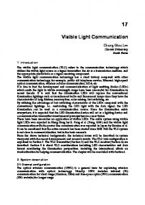
TABLE I: OOK with Manchester Encoding used in OpenVLC1.0 and BFSK Encoding used in our design. Different from OpenVLC1.0, we represent bit ZERO with 4 symbols which are ’1100’(HIGH, HIGH, LOW, LOW), we represent bit ONE with 2 symbols which are ’10’(HIGH, LOW).
ADC
RX
Bit
OOK (OpenVLC1.0)
BFSK (Our Encoding)
0
01
1100
1
10
10
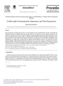
Fig. 1: System Overview: The ambient light cancellation block will filter the ambient light, leading to a ZERO output corresponding to the reception of ambient light, thereby enhancing the reception of VLC packets.
One Byte Bit 0 0
III. S YSTEM OVERVIEW In this section, we describe the system design and implementation as shown in Fig. 1.
0
0
0
Bit 0 1 1
11
receiver. They observed that the SNR varies with the ambient light level and the distance between the transmitter and receiver. While in this paper, we argue that the SNR can be maximized by nullifying the background noise. Schmid et al. in [5] presented a LED-to-LED communication system which demonstrated a data rate of 800bps with an operating distance of 2 meters. The Linux Light Bulb idea was proposed by Schmid et al. in [6]; they embedded a wireless System-ona-Chip (SoC) running OpenWRT into a normal light bulb to connect to the Internet. The performance of this bulb, especially the reliability of communication, is not yet reported. More recently, OpenVLC1.0 was proposed as a low-cost embedded VLC platform [7]. It has a full IP stack and can use LED or photodiode as the receiver. One key problem with this prototype is its limited reliability and robustness. Heydariaan et al. in [3] has investigated its performance under various experimental settings. It turned out that the platform cannot assure reliable communication with bright ambient light. Zhang et al. in [8] has proposed a new circuit to cancel the minimum offset voltage from the input optical signals. They demonstrate the proposed prototype can be immune towards sunlight and indoor fluorescent lights. However, they did not evaluate the prototype in a dynamic environment. We differ in both the design and evaluation in dynamic and challenging envirionment. Ambient Light Effects:. Li et al. [9] presented a system that can reconstruct human movement using off-the-shelf LEDs and photodiodes. They claimed higher level of ambient light intensity will cause the saturation problem when the photodiode is operating outside the linearity area. Meanwhile, Yang et al. [10] also claimed this effect from the ambient light. Li et al. later proposed a method to fade the effect from ambient noise by recognizing the rising edge of the encoded light pulse from the fluctuated ambient light in [11]. However, this does not cancel the entire interference from the ambient light leading to further effort on the edge detection accuracy.
0
00
0
Fig. 2: Encoding method to represent bit ONE and bit ZERO.
A. Modulation Our goal is to design a modulation scheme, that is robust to light interference, and with a simple logic that is possible to implement mostly in software in a low-cost embedded platform (in contrast to OFDM in high-resource systems such as LiFi [1]). Current low cost LED-to-LED or LEDto-Photodiode VLC systems use variations of On-Off Keying (OOK) modulation scheme due to its simplicity [7]. However, OOK is susceptible to ambient light interference [3]. Although there are other modulation schemes in the broader VLC space (e.g., LED-to-Camera [12], Binary Frequency Shift Keying or BFSK [13]), they do not directly address the ambient light interference in embedded VLC. We use BFSK as the modulation scheme rather than OOK in our design since it is less susceptible to ambient noise. Table I shows the modulation schemes used in OpenVLC1.0 platform and our current design. The transmitter represents bit ’1’ with a frequency, for example, 2𝑘Hz to blink the LED. It represents bit ’0’ with a frequency, for example 1𝑘Hz to blink the LED. Assuming we are continuously sending one byte. We represent the modulated signal in Fig. 2 with the encoding scheme. We use more symbols to represent one bit compared to OpenVLC1.0. Our approach improves robustness, but reduces the communication rate. B. The Receiver The main challenge in the receiver design is dynamics of ambient light in the indoor environment (due to use of different lights at different times, movement of people, etc.) and possible saturation of the photodiode. 1) Dynamics of the Ambient Light : We perform a simple experiment to study the dynamics of ambient light in a typical indoor environment. We deploy the photodiode used in OpenVLC node in four different scenarios and plot the
Fig. 3: Ambient light in different lighting settings.
input
output Adaptive DC Restoration C2
R1
de
o An
D1 th Ca
A2
od e
C1
P1
Fig. 5: Comparison of received light signal both with and without ambient light cancellation from the photodiode upon light reception and outputs 𝑉𝑜 . DC restoration. The DC restoration will generate the compensating current to the summing point between the photodetector amplifier and the DC restoration. We add the adaptive components (Fig 4) to the basic DC restoration circuit [14]. Algorithm 1 Adaptive Cancellation Algorithm
R2 C3
ADC
R3 A1
R4
Photodetector Amplifier
Vo
Fig. 4: Ambient Light Cancellation Circuit Diagram consisting of one block for photodetector amplifier, one block for DC restoration, and one for adaptive cancellation, which uses feedback from the output voltage 𝑉𝑜 using a potentiometer (P1) and a LED indicator (D1). The input and output interface to the embedded VLC board.
voltage output from the photodiode in Fig. 3. In a dark environment, the output is close to 0, except for some jitters due to light from LEDs in electronics. With stable lighting in indoor environment, the voltage is nearly constant except for jitters (constant). Occupants’ movement can cause fluctuation in light levels on the receiver (dynamic). Finally, when the light is too bright, the photodiode can get saturated (bright) meaning the output voltage will no longer increase. A receiver must be able to cope with all these variations it may encounter in an indoor deployment. 2) Ambient Light Cancellation: While DC restoration circuit [14] has been used to remove the effect of constant ambient light, those designs do not directly address the dynamics in ambient light in typical indoor deployments. A static DC restoration circuit would not work in the range of scenarios explored in Fig. 3, which can all occur in a single deployment. The compensated current generated from the circuit needs to be adaptively adjusted in the presence of these ambient light changes with a feedback and control mechanism. The mechanism (Fig. 4) has three main parts: Photodetector Amplifier. This amplifier amplifies the current
Input: WS (WindowSize) in 1: numZero = 0; numOne = 0 2: count = 0; min = 0; max = 255 3: mid = read from potentiometer 4: minSps = 20% * WS; maxSps = 75% * WS 5: while 𝑇 𝑅𝑈 𝐸 do 6: value = read one symbol from ADC 7: count++ 8: if value == 0 then 9: numZero++ 10: else if value != 0 then 11: numOne++ 12: end if 13: if count == WS then 14: count = 0 15: gap = numZero-numOne 16: if (gap>minSps) and (numZero>maxSps) then 17: min = mid ; mid = (max+min) / 2 18: write (mid) to potentiometer 19: else if (-gap>minSps) and (numOne>maxSps) then 20: max = mid ; mid = (max+min) / 2 21: write (mid) to potentiometer 22: else if (∣gap