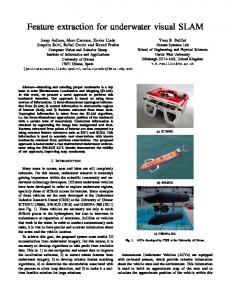
Towards Gaussian Multi-Robot SLAM for Underwater Robotics Dave Kroetsch
[email protected]
Christoper Clark
[email protected]
Lab for Autonomous and Intelligent Robotics University of Waterloo Waterloo, ON N2L 3G1 Phone: 519-888-4567 x5220 July 25, 2005
Abstract This paper presents initial steps towards developing autonomous navigation capabilities for cooperating underwater robots. Specifically, Simultaneous Localization and Mapping, or SLAM , capabilities are investigated for a group of micro vehicles each equipped with a single downward facing camera and an Inertial Measurement Unit (IMU). To verify the approach, simulations of the multi-robot SLAM running in a 3D environment were conducted, where vehicles in close proximity of one another exchange maps to improve localization.
Enabling autonomous navigation in multi-robot systems is key to making them practical. Simultaneous Localization and Mapping (SLAM), provides a means for autonomous vehicles to navigate in previously unknown environments. SLAM constructs a map of the environment, while at the same time providing a position estimate of the robot within the map.
To enable autonomous navigation, the SLAM algorithm must be scalable and real-time capable. Constant-time implementation is critical, so that an arbitrary number of robots and landmarks can be added to the map without the implementation growing to be intractable. Furthermore, the SLAM algorithm cannot be run on a single centralized server or 1 Introduction robot. Underwater communication is unreliable and This research is motivated by applications involving limited in range, forcing decentralized control and the use of cooperating underwater robots for bio- SLAM, with only periodic exchanges of map inforlogical sampling in near-shore water environments. mation. Lakes and oceans provide us with some of our most In this paper, the proposed approach is to merge valuable resources. To manage and conserve these re- world models from multiple vehicles using a method sources requires understanding them, which can only similar to fusing multiple measurements with the be accomplished through directed sampling stud- Kalman filter. This approach was originally demonies. In particular, near-shore water environments are strated with data from land vehicles [1] [2], which complex systems - both in their diversity and dy- extended the Sparse Extended Information Filter namics - that require spatial and temporal surveys (SEIF) [3] from single robot implementation to mulover large areas. Multi-robot systems offer several tiple robots. The approach was shown to be scalable, potential advantages, including the ability to simul- be real-time capable, and function well when decentaneously sample such larger areas. tralized within ad hoc communication networks.
To validate this approach, simulations were conducted in which multiple underwater vehicles successfully carried out 3D SLAM and map merging. The simulation included a full modelling of the vehicle dynamics, but assumed landmarks were easily identified. In order to implement this functionality on a robot, a vision system is required to select landmarks, identify previously observed landmarks and compute their position relative to the craft. What follows is a brief review of related literature, an explanation of the SLAM implementation, a description of how landmarks are identified for the SLAM algorithm, results including simulations, conclusions and future work.
2.2
Multi-robot SLAM
This research concerns SLAM for multi-robot systems, where robots can cooperatively map the environment and localize themselves. For ground-based rovers, several approaches have been taken to this problem. Some approaches assume known starting positions [9]. This assumption was not required for the approach taken in [1], which was also shown to be scalable, be real-time capable. In related work [10], the issue of low-bandwidth communication is taken into consideration by only exchanging those landmarks that result in the highest information gain. Other approaches include [11], where the Set Membership SLAM, or SM SLAM, is extended to multi robot case. In this case, measurement noise and motion error are not assumed to be Gaussian 2 Background distributions, but are instead viewed as unknown but bounded errors. An example of performing multiSLAM - Simultaneous Localization and Mapping - robot SLAM using vision is found in [12]. addresses the problem of using a robot to map an environment, while at the same time localizing the SLAM robot within that map. For the most part, SLAM has 3 been addressed for single ground-based robot systems and is traditionally implemented using a Kalman Fil- The technique presented in [1] enables the merging of multiple world maps that consist of landmark state ter approach [4]. estimates and associate covariance. The technique is an extension of the Sparse Extended Information Filter (SEIF) work presented in [2], which was designed 2.1 Underwater SLAM for a single robot implementation and then extended to multiple robots in cite [1]. In both [1] and [2], the Unlike ground-based mobile robots, SLAM for under- SLAM algorithms were implemented for a 2D enviwater vehicles has only recently been investigated. ronment, (i.e. using a truck in a city park). Here the The first instance of running SLAM on underwa- system has been extended to 3D, an obvious requireter robots appears in [5], where point features, or ment for operating in the underwater environment. landmarks in from the natural environment, were exMuch like the typical Kalman Filter, this approach tracted through sonar. Sonar is also used in [6] to uses a Motion Update to predict the new location verify a constant time SLAM algorithm. The SLAM of the vehicle and a Measurement update to correct implementation in [7], uses a sensor fusion (sonar and this predicted estimate at every time step. Unlike the vision) before feature extraction to make the algo- Kalman Filter approach, a Sparsifiction step is used rithm more robust. to reduce the algorithm run time. Also, additional Another approach is to drop transponders at un- map merging step is taken if vehicles have the ability known locations, and use these transponders as land- to communicate. In summary, each individual vehicle marks in the SLAM algorithm. In [8], ranges to iterates on Algorithm 1 shown below. transponders were used to estimate the vehicle and transponder locations.
Algorithm 1 Multi-Robot SLAM Algorithm for each individual vehicle. 1. Loop on t 2. Motion Update 3. Measurement Update 4. Sparsification 5. If communication with other vehicle exists 6. Merge Maps with other vehicle 7. end Loop
3.2
Measurement Updates
3.1
As more features are observed, the existing links between all previously observed features would remain continuously active. In order to preserve the constant time nature of this algorithm, sparsity constraints are made on the information matrix. For this implementation, features are deactivated as they leave the robots field of view. That is, their links to other features or robots are removed.
The measurement update uses current measurements zt with variance Z to correct the predicted state estimates as follows: ¯ t + Ct Z −1 CtT Ht = H
(5)
bt = ¯bt + (zt − zˆt + CtT µt−1 )T Z −1 CtT
(6)
In equations 5 and 6, zˆt represents the measurement that is expected given the current state estiWithin Algorithm 1 landmarks are not described mate. The measurement Jacobian C is defined by: t with position mean µ and variance σ, but with a com∂h ∂h bination of their inverses. That is, at some time step Ct = [ 0...0 0...0 ] (7) ∂x ∂y t t t, landmarks are defined by the state information matrix Ht and information vector bt . In equation 7, h is the measurement function, xt is −1 the robot pose variable, and yt is the feature position Ht = Σ t (1) variable. It is noted that Ct is sparse, which means that updates are only conducted on the fields which bt = µTt Ht (2) are affected by the current robot pose and the curIf m and n are the number of robots and features re- rently observed features. This allows for a scalable spectively, each with 6 degrees of freedom, then state algorithm that can be run in real-time. vector b ∈