Towards In-Flight Detection and Accommodation of Faults in Aircraft Engines Randal Rausch*, Daniel E. Viassolo†, Aditya Kumar†, Kai Goebel‡, Neil Eklund‡, Brent Brunell†, Pierino Bonanni† GE Global Research, Niskayuna, NY 12309
To effectively accommodate safety critical faults in-flight it is necessary to rapidly detect them and to have a means to accommodate the fault. We present results on model-based fault detection using sensor residuals from an extended Kalman filter with an embedded real-time engine model to characterize un-faulted behavior over the flight envelope. Thereafter, we present an approach for online fault accommodation via optimal changes in a set of suitable adjustments in the existing FADEC control logic. These optimal adjustments are obtained through off-line optimization for optimal recovery of stall margins and thrust and interpolated online for the existing flight conditions. We present results of the fault detection & accommodation applied to a high-bypass commercial aircraft engine over the flight envelope.
Nomenclature ACC ALT CLM CWS DTAMB EGT FADEC GA HPC HPT LPC LPT TRA PS3 VBV VSV XM
= = = = = = = = = = = = = = = = =
Active Clearance Control Altitude Component Level Model (software) of high bypass, two rotor, turbofan Cycle WorkStation software model of high bypass, two rotor, turbofan Delta from ISO standard day temperature Exhaust Gas Temperature Full Authority Digital Electronic Control Genetic Algorithm High pressure compressor High pressure turbine Low pressure compressor Low pressure turbine Throttle Resolver Angle HPC exit static pressure Variable Bleed Valve Variable Stator Vane Mach number
I.
Introduction
F
AULT detection typically waits until a sufficiently large fault signature is present before an alarm is raised. However, faults that affect aircraft safety must be detected quickly. Otherwise, undesired consequences may arise such as engine surge/stall events, power loss, severe vibrations, and no thrust response to commanded power. These events in addition to inappropriate crew response may lead to accidents [1]. Since air traffic is projected to increase in the long term, the number of accidents would also increase given the current level of reliability. To reduce this projected number of accidents NASA established the Aviation Safety Program [2]. Within the scope of this program, this paper investigates a number of faults for which in-flight accommodation is considered. *
Research Scientist, Advanced Computing Technologies, K1-5B37, One Research Circle, Niskayuna, NY 12309. Research Scientists, Electronic & Photonic Systems Technologies, {KW-D211A, KW-D208, KW-D210, KWD218} One Research Circle, Niskayuna, NY 12309 ‡ Research Scientists, Information & Decision Technologies, {K1-5C4A, K1-5C37B}, One Research Circle, Niskayuna, NY 12309. Contact Author: Aditya Kumar,
[email protected], (518) 387-6716 †
1 American Institute of Aeronautics and Astronautics
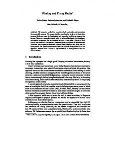
Based on the review of an engine events database of the past 20 years of DEC and FADEC operated aircraft a list of root cause faults was compiled. From this list a set of representative cases from different categories including sensor faults, actuator faults, and gas-path component damage was chosen. More specifically, compressor damage, turbine damage, variable stator vanes faults, and pressure sensor (PS3) fault were selected. The results of these failures can lead to compressor stall, loss of power, loss of thrust control, and flameouts. Thus, fast on-line detection of these faults is desired to enable appropriate fault accommodation and avoid serious engine performance loss or worse, aborted take-off (ATO) or in-flight shut down (IFSD). Also, a timely detection of these faults when they are small in magnitude will enable corrective maintenance to avoid more severe and costly consequences of the faults as they grow in magnitude. However, any fault detection method must have very small false positive alarm rates and missclassification to avoid nuisance and worse, automated implementation of a wrong accommodation that may be more detrimental than no fault accommodation. The aim for early detection of small magnitude faults with acceptable reliability is very challenging, especially in the presence of sensor noise, unknown engine-to-engine variation and deterioration and modeling uncertainty. In this work, we present results on on-line model-based detection of above-mentioned faults and automated online fault accommodation applied to a commercial, high-bypass, twin-spool, turbofan engine (for a survey on modelbased detection, see [3]). Figure 1 shows the overall architecture for the model-based fault detection and online fault accommodation. We explored several fault detection techniques, including: (i) simple rule-based sensor change detection, (ii) multiple-hypothesis correlation testing, (iii) neural networks, (iv) support vector machines, and (v) decision trees. With the exception of the first method, which focused on detection of abrupt changes in the sensed engine variables and simple logic for fault classification, the other methods used the sensor residuals obtained from an online extended Kalman filter (EKF) designed to enhance the difference between the faulted engine and an unfaulted engine model, while being robust to sensor noise and engine-to-engine variation & deterioration. The multiple hypotheses k-means and the neural network algorithms were selected for implementation in conjunction with a simple fusion algorithm that aggregated the output of the two classifiers. The results on the fault classification and magnitude are then used in the fault accommodation to enable best possible recovery of pre-fault operability & performance. In particular, for the compressor & turbine faults and the VSV actuator faults, we developed fault accommodation tables for online calculation of optimal adjustments in the existing FADEC control logic that affect the control action in a desired manner to recover lost stall margins and thrust control without violating any safety limits. On the other hand, for the PS3 sensor fault, the accommodation strategy involves replacing the faulty PS3 sensor with an estimated PS3 value in the FADEC logic, where the PS3 value is estimated using the remaining engine sensors and a specially tuned EKF. FADEC Optimal adjustment s
+
Fault Accommodation Schedules
Fault type, confidence, magnitude
Fusion Algorithm
Actuator s
+
Existing FADEC Logic
Engine (CLM)
Output
Fault Detection residual Algorithms s •Multiple Hyp. •NN
+
EKF (CLM)
Sensors
Figure 1: Fault detection and accommodation architecture In the following sections, we describe in more detail the faults addressed in this work, the model-based fault detection and fault accommodation and the results through model-based simulation studies.
II.
Engine Models
For this study, two nonlinear models of an advanced commercial high-bypass twin-spool turbofan engine were used. Both models can be run in a transient or steady state mode. The first is the truth model that is used to simulate the nominal/faulty engine. The model used for this purpose is the cycle workstation (CWS), which is a high fidelity physics-based aircraft engine model. Variation, deterioration, and fault models can be injected into the CWS model. 2 American Institute of Aeronautics and Astronautics
The CWS model is coupled with the existing FADEC control code for closed-loop engine simulations. The component level model (CLM) is used as the embedded model in the EKF to aid in fault diagnostics (see [5] for related work using a bank of Kalman Filters). The CLM is also physics-based but it is simplified to achieve fast realtime execution while sacrificing some accuracy compared to the CWS. Figure 2 shows the top-level inputs and outputs to the CLM. Flight conditions ALT, XM, DTAMB Fuel Flow VBV 9 Sensors (Y) Temperatures 4 Inputs (U) Pressures VSV CLM Engine Speeds ACC Param eters (P)
Figure 2: CLM inputs, parameters, and sensors The CLM is a continuous time transient model with the following mathematical description:
x&t = f ( xt , pt , ut ) ,
y k∆t = h( xk∆t , p k∆t , u k∆t )
where the state x, comprises the engine spool speeds and temperatures 9 states in total followed by several turbine clearance model states and a few sensor dynamic states. The input u has the 4 control inputs WF36, VBV, VSV, ACC, the environmental variables of altitude (ALT), mach number (XM), and ambient temperature (DTAMB). The CLM output, y, contains the 9 sensed outputs. The parameter vector, p, contains the engine health parameters in terms of efficiency and flow adders/scalers for each of the engine components – fan, booster, high pressure compressor (HPC), high pressure turbine (HPT), and low pressure turbine (LPT) – seal leakage scalars, and turbine clearance adders. These parameters are used to model engine-to-engine variation and deterioration.
III.
Diagnostics
In this section, we describe the faults addressed in this work for online detection and accommodation, and describe the overall model-based fault detection approach and its performance. A. Selected Faults
One of the goals of this project is to create general diagnostic technologies for the different components of an aircraft engine system. To that end we wanted to select actuator, engine, and sensor faults. We selected the variable stator vanes (actuator), high-pressure compressor and high-pressure turbine damage (engine), and Ps3 sensor as the components that are the most suitable to investigate for this project based on an investigation of an engine events database of the past 20 years of DEC and FADEC controlled engines. The fault block diagram is shown in Figure 3. Actuator Fault Engine Control
Ucmd
Actuators
HPC/HPT Fault Utrue
Engine
Sensor Fault
Sensors
Y
Figure 3: Fault block diagram For each of the faults considered, we investigated the three different fault magnitudes small, medium and large. The model values of these component faults is shown in CWS in Table 1. For a more detailed description of these faults and their modeling, see our previous work in [7]. Table 1: Fault modeling Fault Type HPC fault HPT fault VSV fault Ps3 fault
Model Parameter Change From Nominal Changed Small fault Medium fault Large fault -1.5% -3% -5% Efficiency Flow -1.5% -3% -5% -1.5% -3% -5% Efficiency Flow -1.5% -3% -5% Bias 0.8 deg 2.5 deg 5.0 deg Bias -7 PSI -19 PSI -30 PSI
3 American Institute of Aeronautics and Astronautics
B. Fault Diagnostics Results
In this project, we explored multiple algorithms for the detection of the afore-mentioned faults, their classification and magnitude identification (needed for accommodation). In particular, the different algorithms developed included: 1) Crisp rule based abrupt change detection – this method used simple logic to detect rapid changes in sensed engine outputs at steady-state operation and classify them as one of the four fault types. 2) Multiple hypotheses testing (MHT) – this method used the EKF generated sensor residuals and performed a hypothesis test using the correlation of these residuals with pre-computed fault signatures (with similarities to k-means classification). Output were both relative probabilities of the four faults and no fault as well as the magnitude of the fault when it is detected and classified. 3) Neural network (NN) – this method used a bank of neural networks for the fault/no fault identification and classification as well as the fault magnitude using the EKF generated sensor residuals. 4) SVM – this method first employed rigorous techniques for feature selection (including the EKF residuals). It was designed specifically for rapid detection of faults within the time limits allowed and used banks of binary SVMs for fault classification. 5) Tree-based fault classification – this method used the EKF residuals and a set of fault tree logic to detect the presence of a fault and classify it by comparing the residuals against thresholds obtained from statistical analysis of no fault/fault data. From the set of above fault detection algorithms developed in this work, two were selected for implementation in the FADEC – MHT & NN. The selection of these methods was decided in part based on their performance (especially in terms of calculation of a probability/confidence of the identified fault/no fault – used subsequently in the fusion, and the calculation of the fault magnitude – used in the fault accommodation), and convenience for realtime implementation in the FADEC. The performance of the MHT & NN algorithms was complementary: while the MHT algorithm provided excellent results for all fault types except HPC fault for which it had a slightly worse performance, the NN algorithm provided good results for all faults and excellent results for the HPT fault. A simple fusion algorithm was then employed to combine the results on identified fault/no fault condition, probabilities of these events and the fault magnitude from each individual method and obtain the overall fault type and magnitude. The fusion algorithm used a weighted averaging of the results from the 2 methods using the identified probabilities from the respective methods as the weights, and persistency check to obtain the overall fault type & magnitude result – which are used subsequently in the fault accommodation. An objective of the fault detection is to achieve good detection & classification performance with very low false alarm and fault miss-classification rates, since the accommodation based on a wrong fault type would unnecessarily compromise the performance of a healthy engine or an engine with a miss-diagnosed fault type. Thus, the fusion algorithm was tuned to achieve not more than 0.1% false alarm rates and not more than 0.2% miss-classification. Figure 4 shows the overall architecture of the EKF residual generation, the individual MHT & NN fault detection algorithms and the fusion algorithm. Multiple Hypothesis Testing Fault Signature
Regime Selection
Probability, Fault Type & Magnitude
Flight Condition (Alt, XM , DTAMB, TRA)
PostFilter
Fault type, probability, magnitude
Fusion Algorithm EKF residuals
PreFilter
Overall fault type & magnitude
Neural Network Probability & Fault Type
PostFilter
Fault type, probability, magnitude
Fault confidence thresholds
HPC / HPT/ VSV fault magnitude
Figure 4: Overall Fault Detection Fusion Architecture 4 American Institute of Aeronautics and Astronautics
We studied the performance of the MHT & NN fault detection and fusion algorithms using an extensive set of data generated through the high-fidelity CWS model. The data consisted of more than 2000 runs for each fault type & magnitude combination at different points in the flight envelope, TRA level, with different engines with normally distributed engine-to-engine variation and uniformly distributed deterioration level, and sensor noise. A subset of this large dataset was used to tune the MHT, NN and the fusion algorithms and the overall diagnostics performance was studied for the full data set. Table 2 shows the overall confusion matrix for the fault diagnostics for each fault type and magnitude. The results show excellent performance in detection & classification of the faults for each type and magnitude, with 0.1% false alarm rates and 0.2% miss-classification rate – note however that to achieve such low false alarm & miss-classification rates, the algorithm had to sacrifice some performance in terms of missed detection of faults, especially small faults and small/medium/large VSV faults. Figure 5 shows the performance of the MHT & NN algorithms and the fusion results for an example case with medium HPT fault. In this case, the NN algorithm initially correctly identifies the fault type as HPT fault but later miss-classifies it as HPC fault type, while the MHT algorithms correctly identifies it as HPT fault throughout. The fusion algorithm yields the correct fault type by giving more weight on the results from the MHT algorithm owing to its higher probability for HPT fault. Similarly, in other cases with HPC fault type the fusion algorithm allows emphasizing the better performance of the NN algorithm over the MHT, thereby yielding improved results than either individual algorithm. Table 2: Performance of Fault Detection & Fusion algorithms
• Sample case of medium HPT fault where NN by itself yields a wrong result (HPC) • MHT yields the correct result • Fusion enables achieving best of both algorithms
Figure 5: Example case of medium HPT fault with fusion algorithm emphasizing the better performance of the MHT 5 American Institute of Aeronautics and Astronautics
algorithm over the NN algorithm
IV.
Fault Accommodation (FA)
A. Fault Impact and Accommodation Goals
A successful FA strategy is one that regains the engine operability lost from a fault occurrence. Critical measures of engine operability are the stall margins for the fan, booster, and high-pressure compressor. The accommodation goal is to achieve steady state stall margins in a faulted engine that are equal to (or better than) pre-fault margins. In addition, the accommodation action must not cause the exhaust gas temperature to exceed limits, and should not result in a large change in thrust. Related programs include the work in [6]. The CWS simulator is used to predict the dynamic behavior of a production engine and its controller (FADEC) with a high degree of fidelity. In general, after a fault affects the engine, the FADEC attempts to recover fan speed and thus, thrust. Also, EGT increases and stall margins decrease. Figure 6 aggregates results for a total of 458 flight envelope points through a histogram showing the frequency of occurrence of a particular percentage change in each parameter in steady-state. The percentage change is computed using the formula r r Yt final − Yt0 v .100 Yt 0 Figure 6 shows that HPC faults cause significant drops in booster and compressor stall margins. Similar studies show that HPT faults and VSV faults cause a clear drop of the booster and high-pressure stall margins of the engine under FADEC control. In contrast to the HPC, HPT & VSV faults, the PS3 fault does not have any operational impact at steady state, and it affects only the transient operation during TRA burst/chops by limiting the accel/decel schedules to safeguard against stall margin, speed, temperature limits and flame blowouts. HPC fault FUEL FLOW
VBV EXIT ARE S
150
S TA TOR V ANE ANG
1
100
HPT A CC POS
500
400
400
0.5
300
300 0
0
200 200
50
-0.5
0
5
10
-1
100
100 0
0.5
N1
1
0 -10000
-5000
N2
150
5000
0 -40
-20
T25
200
0
20
P25
500
150
400
150
100
0
100
300 100 200
50
0 -0.6
50
-0.4
-0.2
0
0.2
50
100
0 -2
-1
T3
0
0 -400
1
-200
PS3
150
150
100
100
0
200
400
0
0
5
T495
10
Control Mode
80
500 400
60
300 40
50
0 -2
200
50
0
2
4
6
0 -3
FAN SM
20
-2
-1
0
0
1
100 0
2
B OOSTER SM
150
100
4
6
8
60 40
50
-4
-2
0
2
2
4
6
8
6
8
FAR4/THETA 80
100
60 40
50
20 0 -6
0
100
80 100
0
HPC SM 150
0 -80 -60 -40 -20 0 Perc ent Deltas((end-beg)/beg) for RF03
20 0 -20
-10
0
10
20
0
0
2
4
Figure 6: Histograms with steady-state changes in percentage due to HPC faults B. Architecture and Strategy for Fault Accommodation
The architecture proposed for FA is displayed in Figure 1. As shown there, for a given fault type and magnitude, we propose to change a subset of the FADEC adjustments and thus recover losses in stall margins while maintaining pre-fault thrust and acceptable EGTs. This architecture is accurate for FA of HPC, HPT, and VSV faults. In more loose terms, it also captures our strategy for Ps3 accommodation where an extended Kalman filter (EKF) is designed for Ps3 estimation under Ps3 sensor fault using the remaining available engine sensors. 6 American Institute of Aeronautics and Astronautics
For HPC, HPT and VSV faults, we have taken a two-step approach. In the first step, we design optimal fault accommodation schedules using off-line model-based optimization for the identified FADEC adjustments. In the second step, we implement on-line interpolation using the developed schedules to address the on-line fault accommodation. In this paper, we review comprehensive results for HPC fault accommodation following this twostep approach, and test its robustness to flight/engine variations. The strategy developed for FA is described through the following steps: 1. Estimate fault type and magnitude using detection and fusion algorithms 2. If the fault is a Ps3 sensor fault: Replace sensed Ps3 value by estimated Ps3 value (using EKF) 3. For HPC, HPT or VSV faults a. Use fault type, fault magnitude, and flight envelope (FE) data to determine FADEC adjustments from a pre-computed lookup Table b. Apply FADEC adjustments The lookup table is composed of 3 sub-tables, one for each fault type (see Figure 7). Inputs to these tables are flight envelope data (TRA, and sensed inlet temperature T12 and pressure P0), and fault data (fault type and magnitude). The outputs are the FADEC adjustments.
P0, T12, T RA
Figure 7: Look-up Table for FA of HPC, HPT, and VSV faults The individual look-up tables are constructed offline by fixing table inputs (fault data and FE data), and finding the best FADEC adjustments to achieve our FA goals via optimization. These are the FADEC adjustments for the table nodes or design points. For generic inputs (fault data and FE data), the corresponding FADEC adjustments are computed through online interpolation. More details on the optimization/interpolation steps follow. Table 3: FADEC adjustments identified for FA Definition Variable Bleed Valve Adjustment Adder Variable Stator Vane Adjustment aAdder Horsepower Extraction Throttle Resolver Angle Auxiliary Compressor Bleed Switch
Table 3 lists all the identified FADEC adjustments that can be used for FA. In general terms, the optimal adjustments are found by solving the following problem Minimize FADEC adjustments Cost s.t. Constraints The cost penalizes losses in fan, booster, and HPC stall margins as well as changes in thrust. It also penalizes changes in the adjustments from their nominal values to thus give preference to solutions with low “accommodation effort.” The constraints enforce the EGT upper-limit and use the FADEC logic to enforce actuator constraints. For the optimization we use a derivative-free global optimizer (Genetic Algorithm) together with a high-fidelity model of the engine in closed-loop with the FADEC; see Figure 8. 7 American Institute of Aeronautics and Astronautics
GA C o n tro l A d ju s tm e n ts F l i g h t C o n d i ti on s
F A D EC
A c tu a to r C o m m a n d s
E n g i ne S i m u la ti o n
Figure 8: Schematic showing the global optimizer (GA) in connection with the FADEC + engine simulation A previous formulation of this optimization used more adjustments then the ones listed, which resulted in good recovery of pre-fault stall margins and thrust for table nodes, but highly discontinuous adjustments. Very different sets of adjustments were assigned to two node points very close in the FE, leading to adjustments with poor FA capabilities for points in between these nodes. Reducing the number of adjustments to the minimum possible, together with including in the cost a penalty on the adjustments’ departures from their nominal values, gave us good solutions for both table nodes and generic FE points for the current formulation. Figure 9 shows the selected design and testing points in the Altitude-Mach (ALT-XM) plane, as well as in the inlet sensor plane P0-T12. C. FA for Large HPC fault
Let us focus now on the HPC fault type and large fault magnitude. By solving optimization problems offline, the optimal adjustments for the design points are obtained for two different TRA values: TRA=50 and TRA=75. FA adjustments needed for other TRAs are obtained through interpolations. Optimal TRA adjustments turned out to be very close to their nominal values of 50 or 75; therefore, for simplicity, we are not going to be using TRA adjustment for FA of HPC faults.
Figure 9: Design Points & Testing Points used to design and test the FA strategy. Point locations in the ALT-MACH plane (left) and T12-P0 plane (right) The interpolation problem is to determine, from the adjustments computed for the design the set of adjustments needed to accommodate a fault for given arbitrary point in the FE (i.e., arbitrary values of P0, T12, TRA). Our experience shows that the particular interpolation method to be used in our FA approach plays a key role. The approach proposed in this paper is to compute the FA adjustments as the weighted average of the adjustments corresponding to the N closest design points in the P0-T12-TRA space. The weights are given by the normalized inverses of the distances to the corresponding design points. FA results for TRA=60 are shown in Table 4, where we list stall margins and thrust before and after fault with and without accommodation for all 8 test points A, B, …, H. As can be seen from these tables, this FA strategy is quite successful. Notice that TRA=60 is not one of the TRAs for which we optimized offline (these are TRA=50 and 75), so we are in the most general interpolation case. Similar studies to the one in Table 4 were performed for other TRAs (35,50,75,85), and in all cases our FA approach proved to be successful. 8 American Institute of Aeronautics and Astronautics
Table 4: FA performance for Testing Points for TRA=60, half deteriorated engine, large HPC fault H
% change w ithout FA
SM fan SM boost SM comp Thrust Adjustment 60
G
F
1.3038
-3 0 -2 0 -0.047489
-1 0 -1 0 -0.53023
1
-2 0 0 0 -1.3675
SM fan SM boost SM comp Thrust Adjustment
B
1.3585
% change with FA
-2 -27 -3 0 22.09
SM fan SM boost SM comp Thrust Adjustment
C
% change with FA
-1 -25 -5 0 22.805
% change w ithout FA
SM fan SM boost SM comp Thrust Adjustment 60
-1 0 0 -1 0.19026
D
% change with FA
-2 -27 -3 0 26.641
% change w ithout FA
SM fan SM boost SM comp Thrust Adjustment 60
E
-2 -27 -4 0 18.741
% change w ithout FA
SM fan SM boost SM comp Thrust Adjustment 60
% change with FA
SM fan SM boost SM comp Thrust Adjustment
A
2.8464
SM fan SM boost SM comp Thrust Adjustment
% change w ithout FA
60
-2 -28 -5 0 18.632
% change w ithout FA
60
60
1.2864
-4 0 -2 0 -0.16863
1.5495
% change w ith FA
-2 -27 -5 0 20.15
% change w ithout FA
-1 0 0 0 0.17883
% change w ith FA
-2 -28 -3 0 31.155
% change w ithout FA
60
% change w ith FA
-1 0 -1 0 0.10112
1.1855
% change w ith FA
-2 -24 -5 0 21.254
-1 0 -2 0 0.26112
1
Figure 10: Time responses (normalized) for actuators, stall margins, thrust and EGT under large HPC fault with FA (magenta) and without FA (blue). HPC fault enters at 0.5 sec., accommodation is enabled at 2.5 sec. Actuators (1st row) are normalized with respect to max allowed values; SMs and Thrust are normalized with respect to their prefault values; EGT is normalized with respect to max allowed EGT D. Robustness Analysis for the FA approach
We assume that engine variation due to deterioration dominates other causes of variation. Note that to compute FA adjustments for the design points we have been using half-deteriorated engine models. A simple robustness analysis consists in determining the FA performance of these adjustments when used to accommodate faults for new engines and for full-deteriorated engines. Table 5 shows FA performance for some testing points for new engine at TRA=85 (high TRAs are the most challenging for FA); a similar table is available for full-deteriorated engines (not shown). In principle, the FA results for Booster SM for new engine appear not to be too promising. However, if we look closer, the Booster SMs recovered by FA for a new engine are larger than the non-fault Booster SMs for fully deteriorated engines (for all testing points). Thus, we claim that FA is good enough. The bar charts in Figure 11 illustrate this for some testing points. The same conclusions hold for other TRAs and points in the FE.
9 American Institute of Aeronautics and Astronautics
Table 5: FA robustness for some Testing Points for new engine, TRA=85, large HPC fault % change w it h o u t FA
G S M fa n SM boost SM com p T h ru s t A d ju s tm e n t
85
0 -4 6 0 0 2 1 .6 6 1
% change w it h o u t FA
F S M fa n SM boost SM com p T h ru s t A d ju s tm e n t
85
S M fa n SM boost SM com p T h ru s t A d ju s tm e n t
85
S M fa n SM boost SM com p T h ru s t A d ju s t m e n t
2
-2 -9 -2 1 -3 .1 5 3 3
S M fa n SM boost SM com p T h ru s t A d ju s t m e n t
1
0 -4 6 0 0 2 1 .3 1 3
-5 -1 5 -1 1 -3 .9 2 5 2
Point A
S M fa n SM boost SM com p T h ru s t A d ju s t m e n t
5
Point B
Point G
85
85
After fault With FA
2
-2 -1 0 -2 0 -3 .0 1 4 7
2
% change
-1 -4 0 -1 0 1 8 .8 1 1
-1 -1 6 0 0 -2 .9 8 8 7
2
Point C
Point E
After fault Without FA
-3 -1 3 0 0 -3 .5 8 9 1
% change
-3 -3 6 -4 0 2 0 .4 9 7
% change w it h o u t F A
A
% change
85
% change
0 -4 7 0 0 2 1 .9 7 6
% change w it h o u t F A
B
% change
-3 -3 6 -5 0 1 9 .4 2
% change w it h o u t FA
E
-2 -1 0 0 0 -4 .1 2 9 8
% change w it h o u t F A
C
% change
Point F
Fully det. engine (no fault)
New Engine Half det. Engine Fully det. Engine
Figure 11: Booster SMs for engines at different deterioration levels with/without FA (TRA=85, large HPC) for some test points So far we have been considering only HPC faults of large size. Given the FA adjustments for large faults, the question is how do we compute the adjustments for small size and medium size faults. One straightforward approach is to replicate the strategy we use for large fault to small and medium faults. Instead, we propose a simpler one consisting in downscaling the adjustments obtained for large faults. The selected scaling factors are 2/3 for medium faults and 1/3 for small faults. This simple approach proved to be very effective. E. FA for Ps3 sensor faults
To accommodate Ps3 sensor faults, we propose to replace the faulty Ps3 sensor readings with a model-based estimation of Ps3 via an Extended Kalman Filter (EKF). In particular, we design an EKF using the remaining sensors to obtain a robust estimate of Ps3 in the presence of random engine-engine variation and deterioration. Figure 12 shows estimation errors using this EKF for the 8 available sensors and PS3 (estimated) for idle-to-takeoff transients, for new and deteriorated engines. Even during transients, the EKF estimation is good, with errors of less than 5 psi at initial low power level to less than 10 psi at high power levels. In contrast, the open-loop model estimation error ranges from 15-20 psi. 10 American Institute of Aeronautics and Astronautics
We performed CWS simulation studies adding to the Ps3 sensor reading the expected Ps3 estimation error (computed offline) during an idle-to-takeoff operation. Simulations were done for both a new and a fullydeteriorated engine. In both cases it was found that the FADEC in closed loop with the engine and estimated Ps3, does an excellent job, with responses very close to the ones obtained for the case with no Ps3 error.
New Engine
Fully Deteriorated Engine
Figure 12: Idle-takeoff transient: Estimation errors for the nine sensed engine outputs using EKF (blue) and using an open-loop engine model (red), for new and full-deteriorated engines
V.
Conclusions We presented results on model-based online fault detection for commercial, high-bypass, two-spool, turbofan aircraft engine, focusing on a set of engine, sensor and actuator faults. We developed and implemented two different fault detection algorithms – multiple hypotheses testing & neural networks that analyze the sensor residuals generated with an EKF based on an un-faulted engine model. These two algorithms had complementary performance, which was exploited in a fusion algorithm to enhance the overall detection & classification performance. The fault detection & classification is used for online accommodation to minimize the detrimental impact of the fault on engine operability & thrust control. In particular, we identified a set of suitable adjustments in the existing FADEC logic to retain the basic controls performance and add the fault accommodation by modifying the basic controls based on the identified fault type & magnitude. The optimal values of these adjustments are computed online using a combination of off-line model-based optimization at chosen points in the flight envelope and online interpolation. The fault accommodation strategy has shown promising results for HPC fault type and we are currently working on extending this approach to the HPT & VSV faults. For the pressure sensor fault, the accommodation approach entails the use of a specially tuned EKF to estimate this pressure and replace the faulty sensor in the FADEC logic. Future extension of this work could investigate the application of the proposed fault detection & accommodation approach to a complete suite of engine, sensor and actuator faults to enhance overall reliability and avoid in-flight shutdowns and aborted take-offs. Also, the use of a tracking filter, or model parameter identification, can be explored to better match the embedded model to the specific engine before the occurrence of a fault. This would enable improved detection of small faults occurring at steady state as well as transient operating conditions.
Acknowledgments This work was supported by NASA grant NAS3-01135 Task # 3. The authors greatly acknowledge the support of Don Simon and Tak Kobayashi (both with NASA Glenn Research Center). The authors are grateful to Matt Wiseman of GE Aircraft Engines for very useful discussions.
11 American Institute of Aeronautics and Astronautics
References [1] AIA/AECMA Project Report on PSM+ICR, http://www1.faa.gov/certification/aircraft/engine_psm+icr.doc, 1998. [2] Christine M. Belcastro, Celeste M. Belcastro, “Application of failure detection, identification, and accommodation methods for improved aircraft safety”, Proceedings of the American Control Conference, Vol. 4 , 25-27, pp. 2623 – 2624, June 2001. [3] J. J. Gertler, “Survey of model based failure detection and isolation in complex plants,” IEEE Control Systems Magazine, pp. 1–11, December 1988. [4] W. Yan, K. Goebel, and J. Li, “Classifier Performance Measures in Multi-Fault Diagnosis for Aircraft Engines” Proceedings of SPIE, Component and Systems Diagnostics, Prognostics, and Health Management II, vol. 4733, pp. 88-97, 2002. [5] Takahisa Kobayashi, Donald L. Simon, “Application of a Bank of Kalman Filters for Aircraft Engine Fault Diagnostics”, Proceedings of ASME Turbo Expo 2003, Power for Land, Sea, and Air, June 16-19, 2003, Atlanta, Georgia, USA, GT2003-38550, 2003. [6] C. E. Frankenberger, III “Survivable Engine Control Algorithm Development (SECAD)”, Proceedings IEEE Aerospace Conference, 2002. Volume: 6 ,9-16. pp. 6-3015 -6-3020, 2002. [7] Kai Goebel, Neil Eklund, Brent Brunell (2004). “Rapid Detection of Faults for Safety Critical Aircraft Operation.” Paper #1360, presented at 2004 IEEE Aerospace Conference Big Sky, Montana - March 6-13, 2004.
12 American Institute of Aeronautics and Astronautics