Towards Large-Scale Network Virtualization Panagiotis Papadimitriou† , Ines Houidi§ , Wajdi Louati§ , Djamal Zeghlache§ , Christoph Werle⋆ , Roland Bless⋆ , Laurent Mathy‡ †
Institute of Communications Technology, Leibniz University of Hannover, Germany
[email protected] § Institut Telecom, Telecom SudParis, France {ines.houidi, wajdi.louati, djamal.zeghlache}@it-sudparis.eu ⋆ Karlsruhe Institute of Technology, Germany {werle, bless}@tm.uka.de ‡ Computing Department, Lancaster University, UK
[email protected]
Abstract. Most existing virtual network (VN) provisioning approaches assume a single administrative domain and therefore, VN deployments are limited to the geographic footprint of the substrate provider. To enable wide-area VN provisioning, network virtualization architectures need to address the intricacies of inter-domain aspects, i.e., how to provision VNs with limited control and knowledge of any aspect of the physical infrastructure. To this end, we present a framework for large-scale VN provisioning. We decompose VN provisioning into multiple steps to overcome the implications of limited information on resource discovery and allocation. We present a new resource selection algorithm with simultaneous node and link mapping to assign resources within each domain. We use a signaling protocol that integrates resource reservations for virtual link setup with Quality-of-Service guarantees. Our experimental results show that small VNs can be provisioned within a few seconds.
1
Introduction
The Internet has been experiencing a remarkable emergence of new applications and network services. This is due to the flexibility of the Internet’s original design and the resulting ability to act as a carrier for nearly arbitrary services. While the services on top of the Internet evolved, the core of the Internet remained unchanged over the past decades with the exception of small patches. Thereby, the current Internet infrastructure remains sub-optimal for many network applications that require high performance, reliability and/or security. To overcome this impasse, numerous Future Internet Initiatives [7], [18], [1] leverage on network virtualization to concurrently deploy and operate different network architectures within virtual networks (VNs). Recently, technology has evolved to satisfy the various needs for full network virtualization across multiple administrative domains. Although large-scale VN setup may be technically feasible, VN provisioning and management requires the separation between the
network operations and the physical infrastructure. A newly envisioned level of indirection already exists in GENI [7], 4WARD [1], and Cabernet [18]. In this context, VN Providers (VNPs) that act as brokers for virtual resources between VN Operators (VNOs) and Physical Infrastructure Providers (InPs) will have to provision VNs without having control or even knowledge of any aspect of the physical infrastructure (see [15] for VNP and VNO definitions). This entails serious implications on resource discovery and allocation, since InPs will not be willing to disclose their resource and topology information to third parties (i.e., VNPs). Currently, most existing VN embedding approaches are limited to a single administrative domain, assuming complete knowledge of physical resources and the underlying substrate topology. Thereby, such VN deployments are limited to the geographic footprint of the substrate provider. Recent work [6] presents a multi-domain VN embedding framework, where VN requests are relayed across InPs till the embedding is completed. However, this work lacks the required embedding algorithms and their evaluation and therefore, it is unclear how fast it converges to a full embedding. In this paper, we present a VN provisioning framework that allows VNPs to discover and allocate resources across multiple physical infrastructures with limited information disclosure. Furthermore, we propose a new algorithm with simultaneous node and link mapping for resource assignment within InPs. To provide the required interoperability across InPs for virtual link setup, we use a signaling protocol based on the Next Steps in Signaling (NSIS) framework [8]. Using a prototype implementation, we evaluate the performance of VN provisioning with a diverse size of virtual and substrate networks. The remainder of the paper is organized as follows. Section 2 gives an overview of the provisioning framework. In Section 3, we present our resource assignment algorithm with simultaneous node and link mapping within InPs. Section 4 discusses our signaling protocol for virtual link setup. Section 5 provides experimental results on VN provisioning and performance analysis of virtual link setup. Finally, in Section 6, we highlight our conclusions and discuss future work.
2
Virtual Network Provisioning Overview
In this section, we provide an overview of our multi-domain VN provisioning framework. In contrast to VNs deployed on top of a single shared substrate, multi-domain VN provisioning is coordinated by VN Providers, which have limited resource and topology information of the underlying substrates. Hence, virtual resources should be initially discovered and matched at a rather high level of abstraction (i.e., VNP) to identify candidate resources from which the most appropriate resources will be selected based on detailed information only available to InPs. Thereby, our approach consists in decomposing VN provisioning into the following steps: Resource Advertisement: To facilitate resource discovery, resource/service advertisement from the InPs is required. An InP will not expose any information on the substrate topology nor the number of virtual resource instances it
is willing to provide for the construction of VNs. Separate node and link specifications will essentially describe different types of virtual resources that can be offered by the InPs. Hence, the VNP will be in position to match requested with offered virtual resources across InPs. Thereby, we consider the InPs disclosing a set of offered virtual nodes and links accompanied with static attributes (e.g., node/link type, operating system, number of network interfaces, geographic location) and the associated cost. Virtual resource descriptions are formed by extracting the static attributes from resource repositories at the InPs. Upon receiving any advertised information, the VNP registers it into a local repository which is subsequently used for the resource matching step. Resource Matching: Resource matching is the identification of a set of resources offered by InPs that fulfill the requirements for each individual resource request. We consider a VN request as a weighted undirected graph Gv = (Nv , Lv ), where Nv is the set of virtual nodes nv and Lv is the set of virtual links lv between nodes of the set Nv . For a given Gv request, VNP determines for each nv ∈ Nv the corresponding M atch(nv ) set among resources advertised from InPs. This set essentially includes all possible candidates for each requested virtual node. VN Splitting: Since a M atch(nv ) set may include resources from multiple InPs, the VNP has to decide to which InP each requested virtual node nv should be assigned. Essentially, the VNP should split the VN graph into sub-graphs that will compose the requests for each target InP, while minimizing the cost for allocating all nodes and links across InPs. Previous work [10] provides heuristic and exact methods for VN splitting. Resource Assignment: Resource assignment relies on a selection process within each InP, since full knowledge of the physical resources and topology is required. Each InP assigns its partial VN to the substrate network using a VN mapping algorithm. Unlike most existing work [17], [16], [12], where node and link mapping is achieved sequentially, we develop a new heuristic resource assignment algorithm with simultaneous node and link mapping. The main objective of this algorithm is to optimize load balancing over substrate nodes. Furthermore, our heuristic algorithm yields faster execution than multi-commodity flow algorithms (e.g., [5]), which is critical for embedding VNs onto large physical infrastructures. VN Instantiation: Upon resource assignment, the selected substrate resources are allocated by the InPs in order to instantiate the requested VN. Within each InP, VN instantiation is coordinated by a dedicated management node, which signals requests to substrate nodes for virtual node and link setup. Our prototype implementation uses Xen [3] for node/router virtualization and Click Modular Router [11] (running in the Linux kernel) for packet encapsulation/decapsulation and packet forwarding. Each virtual node request (within each InP) is handled by a separate thread, speeding up VN instantiation. Similarly, separate threads allow VN setup to proceed in parallel across InPs. We use NSIS (and particularly the implementation available in [14]) to carry the required information for
virtual link setup across inter-domain paths. Besides providing interoperability, our signaling protocol improves performance since it couples virtual link setup with resource reservation via the QoS Signaling Layer Protocol (NSLP) [13].
3
Resource Assignment
Assigning VN graphs to shared substrate networks is known as an NP-hard problem. Hereby, we propose a heuristic resource assignment algorithm where node and link mapping phases are simultaneously executed in one stage. 3.1
Embedding Model and Problem Formulation
Substrate Network Model: The substrate network can be represented by a weighted undirected graph Gs = (Ns , Ls ), where Ns is the set of substrate nodes and Ls is the set of substrate links between nodes of the set Ns . Each substrate node ns ∈ Ns is associated with the capacity weight value C(ns ) which denotes the available capacity of the physical node ns . Each substrate link ls (i, j) ∈ Ls between two substrate nodes i and j is associated with the available bandwidth capacity C(ls (i, j)). Let ψ be a set of substrate paths in the substrate network Gs . The available bandwidth capacity C(P ) associated to a substrate path P ∈ ψ between two substrate nodes can be evaluated as the minimal residual bandwidth of the links along the substrate path: C(P ) =
min C(ls (i, j))
ls (i,j)∈P
(1)
Let Vs and Ms denote a node capacity vector and a link capacity matrix, respectively, associated to the graph Gs such that: – Vs =[C(nis )] is the available capacity vector for substrate nodes niv , where 1 ≤ i ≤ |Ns |. – Ms =[C(ls (i, j))] is the available bandwidth capacity matrix for substrate links lv ∈ Ls between nodes nis and njs , where 1 ≤ i, j ≤ |Ns |. Virtual Network Model: An InP receives requests to set up on-demand VN topologies with different capacity parameters over the shared substrate. Each virtual node nv ∈ Nv is associated with a minimum required capacity denoted by C(nv ). Each virtual link lv ∈ Lv between two virtual nodes is associated with a capacity weight value C(lv ) which denotes the minimum required bandwidth capacity of the virtual link lv . We represent a VN request with the quadruple Req = (Reqid , Gv , Vv , Mv ), where Reqid represents the unique identifier for the request Req. Vv and Mv denote a node capacity vector and a link capacity matrix, respectively, associated to the graph Gv , so that: – Vv =[C(niv )] is the minimum required capacity vector for virtual nodes niv , where 1 ≤ i ≤ |Nv |. – Mv =[C(lv (i, j))] is the minimum required bandwidth capacity matrix for virtual links lv ∈ Lv between nodes niv and njv , where 1 ≤ i, j ≤ |Nv |.
VN Mapping Problem Formulation: Based on the substrate and VN models, the challenge is to find the best mapping between the virtual graph Gv and the substrate graph Gs given specific objectives. Our goal is to provide a mapping, denoted by MAP, that optimizes load balancing across the substrate resources with respect to the capacity constraints. Finding the optimal VN mapping solution that satisfies multiple objectives and constraints can be formulated as an NP-hard problem, as follows: Node Mapping: Let MAP N : Nv → NsReqid ⊆ Ns denote a mapping function between virtual nodes and substrate nodes, where NsReqid represents the set of substrate nodes capable of supporting at least one virtual node of a request Reqid, i.e., NsReqid = {ns ∈ Ns | C(ns ) ≥ minnv ∈Nv {C(nv )}}. Link Mapping: Let MAP L : Lv → φ ⊆ ψ denote a mapping function between virtual links and substrate paths, where φ = {P ∈ ψ | C(P ) ≥ C(lv ), ∀ lv ∈ Lv }. 3.2
Resource Assignment Algorithm
We propose a centralized and heuristic resource assignment algorithm (Algorithm 1) with simultaneous node and link mapping. Since our objective is to optimize load balancing over substrate nodes, we use a greedy node mapping algorithm to assign virtual nodes to the substrate nodes with the maximum substrate resources. Once a virtual node nv is assigned, all virtual links directly connected to this node as well as the set of its neighborhood nodes Nei(nv ) are assigned. Virtual link assignment is based on the shortest-path (SPT) algorithm. To accomplish that, two predefined functions are used in this algorithm: SORT and HEAD function. SORT is a sorting function that sorts a vector of nodes (e.g., Ns ) based on their capacities by ordering them from higher to lower capacity. The HEAD function returns the first element (node identifier) of the vector. The SPT algorithm computes a path from node ns to each node k (ns 6= k) so that the weight between node ns and all other nodes is minimum. Let Pk denotes the shortest path between node ns and a substrate node k. The substrate path Pk is associated with the minimum path capacity C(Pk ) between k and ns (see Equation 1). Consequently, the SPT algorithm returns a set Tns associated to the node ns such that: Tns = {(Pk , C(Pk ))∀ k ∈ NsReqid }. For each virtual node j ∈ Nei (Nv ) (starting with the largest required capacity) the algorithm will select the substrate node k such that C(Pk ) is minimal. The node k should also satisfy virtual node and link constraints so that C(k) > C(j) and C(Pk ) > Mv [nv ][j]. Therefore, the virtual node j is assigned to the substrate node k and the virtual link lv (nv , j) is assigned to the substrate path Pk at one stage (i.e., simultaneous node and link mapping). The same process is repeated for the residual VN graph until all virtual nodes and links are assigned. Once the entire request is mapped successfully onto the substrate, the algorithm execution is terminated. In order to satisfy the node and link constraints of incoming VN requests, updated resource information is needed. To this end, the substrate nodes monitor
CPU load and link bandwidth which are subsequently communicated to the InP management node before embedding a requested VN. Algorithm 1 Resource Assignment Inputs: Gs = (NsReqid , Ls ), Vs , Ms Gv = (Nv , Lv ), Vv , Mv SORT(Vv ) SORT(Vs ) nv ← HEAD(Vv ) ns ← HEAD(Vs ) MAPN (nv ) ← ns // Virtual node with largest required capacity is mapped to the substrate node with maximum available capacity SORT(Nei(nv )) for each lv (nv , j) ∈ Lv ; j ∈ Nei (nv ) // Mapping all virtual links directly connected to the virtual node nv and its adjacency list Nei (nv ) do a. Tns ← SPT(ns ) b. k ← {k ∈ NsReqid \ ns ; C(Pk ) isminimal} such that: C(Pk ) > Mv [nv ][j] and Vs [k] > Vv [j] // substrate node k should satisfy the requested node and link constraints i. MAPN (j) ← k ii. MAPL (lv (nv , j)) ← Pk iii. Nv ← Nv \ j and Lv ← Lv \ lv (nv , j) // Removing the already assigned virtual nodes and links from the VN request graph if Nv = ∅ then STOP else GOTO 1 with the residual graph of the VN request Gv end if end for
4
Virtual Link Setup
The setup of virtual links across multiple domains with QoS guarantees requires a resource reservation protocol that supports inter-domain signaling. Recently, IETF approved the Next Steps in Signaling Protocol (NSIS) suite which provides a resource reservation protocol for inter-domain signaling (i.e., QoS NSLP [13]). One major enabler in this context is the generic QoS parameter specification using the QSPEC template [2], which can be mapped to domain specific QoS mechanisms. Irrespective of the herein proposed NSIS-based solution, however, InPs must agree on a common method and signaling protocol to set up virtual links between their domains a priori. We use the NSIS protocol suite (the NSIS-ka implementation [14]) to combine the virtual link setup with the resource reservation signaling via the QoS
1. Setup virtual link from DomU1@A DomU1@B
2. Init virtual link setup DomU1@A DomU1@B
InP Management Node 4. Ignores VLSP object, performs Admission Control
3. RESERVE + VLSP Object
Router A Node Management Agent
NSIS Daemon
Dom U1
CLICK IP in IP tunnel
9. RESPONSE
Node Management Agent
Dom U1 7. RESPONSE
IP forwarding eth0
Router B
NSIS Daemon
NSIS Daemon
10. Setup virtual link DomU1@A DomU1@B
eth0
5. RESERVE + VLSP Object
Router X
Dom 0
eth0
6. Setup virtual link DomU1@A DomU1@B
eth1
8. Reserves resources
Dom 0
eth0 CLICK eth0
virtual link
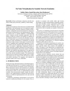
Fig. 1. Virtual link setup.
NSLP. This integration reduces the setup time of a virtual link, as the resource reservation at the same time conveys the necessary address information of the virtual link. A QoS NSLP extension mechanism for carrying new objects is used to convey the newly created virtual link setup protocol (VLSP) object. Only the substrate nodes hosting the virtual nodes at the edges of the virtual link need to support the VLSP object and act on it accordingly by installing any state required for virtual link setup. Intermediate substrate nodes may be involved in guaranteeing QoS properties of the virtual link or an aggregate of virtual links and therefore need to process the QoS NSLP content. They can, however, simply ignore and forward the contained VLSP object, which is ensured by the NSLP object extensions flags in the VLSP object header. The path-coupled signaling approach of NSIS ensures that a viable substrate path with enough resources exists to accommodate the new virtual link. The VLSP object was also used in [4] to carry the required information for virtual link setup combined with authentication. Fig. 1 shows the sequence of events during the setup of a unidirectional virtual link: Router A and Router X belong to InP1, whereas Router B resides in InP2’s infrastructure. For simplicity, we consider Router B acting as gateway border router of InP2. Both routers A and B, which support virtualization, provide a control interface to their corresponding InP management node and run an NSIS daemon that interprets and processes the VLSP object. The intermediate Router X merely needs to perform general QoS tasks, such as admission control, resource reservation, and policing (as a border router), and hence it can use NSIS without any modifications. The setup of a unidirectional virtual link between two virtual nodes (from DomU1@A to DomU1@B, both part of the same VN) is triggered by a request of the InP management node to the substrate node management agent (Step 1 ). This request contains the specification of the substrate link endpoints and the virtual link endpoints. A virtual link endpoint description at least includes identifiers for the VN, the virtual node, and the respective interface but can be easily extended. In Step 2, the request is passed via inter-process communication
(IPC) to the NSIS daemon, which puts the QoS requirements (QSPEC object) and the virtual link description (VLSP object) into a QoS NSLP RESERVE message. In Step 3, a signaling connection with the NSIS instance on Router B is established and the QoS NLSP RESERVE message is sent. As mentioned before, the intermediate Router X only interprets the contained QSPEC object and performs admission control for the virtual link while the VLSP object is ignored (Step 4 ) and forwarded to Router B in the RESERVE message (Step 5 ). On arrival of the RESERVE message at Router B, admission control is performed and on success, resources are reserved and the local end of the virtual link is set up (Step 6). A RESPONSE message is sent back towards Router A (Step 7 ), which causes Router X to reserve the required resources for the virtual link (Step 8 ) and to forward the RESPONSE to Router A (Step 9 ). Router A then reserves local resources and installs the virtual link (Step 10 ), thereby establishing the data plane from DomU1@A to DomU1@B. In Section 5.2, we subject our inter-domain solution to virtual link setup to a detailed performance analysis for the scenario given in Fig. 1.
5
Evaluation
In this section, we use our prototype implementations to evaluate the performance with VN provisioning and provide insights into inter-domain virtual link setup. 5.1
Virtual Network Provisioning
VN provisioning experiments are carried out in the Heterogeneous Experimental Network (HEN) [9] using Dell PowerEdge 2950 systems with two Intel quadcore CPUs, 8 GB of DDR2 667MHz memory and 8 or 12 Gigabit ports. A fixed number of HEN nodes compose the substrate. To explore VN provisioning with multiple InPs, these nodes are split into multiple logical clusters, each one serving as an independent InP. Separate HEN nodes undertake the role of VNP and VNO. First, we evaluate VN provisioning with a single domain. We measure the time required to provision VNs with varying size (3–10 nodes/links). Fig. 2(a) shows the substrate topology which is composed of 10 nodes. In Fig. 2(b), we demonstrate the time required for each provisioning step, including resource discovery, assignment, and VN instantiation. Our experimental results indicate that a VN can be provisioned just in a few seconds, with most time being spent within the InP for virtual node and link setup. More precisely, it takes 3.61 seconds on average across 20 runs with a small standard deviation to provision the VN composed of 3 nodes/links. Resource discovery and assignment are concluded in 0.31 and 0.17 seconds, respectively. Fig. 2(b) also shows that VN provisioning scales within our experimental infrastructure. Varying the size of the requested VN has no noticeable impact on resource discovery and assignment. According to Fig. 2(b), instantiation times
6.0
VNet Instantiation Resource Assignment Resource Discovery
5.5 5.0 4.5
time (sec)
4.0 3.5 3.0 2.5 2.0 1.5 1.0 0.5 0.0 3
4
5
6
7
8
9
10
VNet size
(a) Experimental scenario (b) Time required for VN provisioning Fig. 2. VN provisioning with single InP. 2.5
Resource Assignment Resource Discovery
time (sec)
2.0
1.5
1.0
0.5
0.0 0
5
10
15
20 25 30 35 number of substrate nodes
40
45
50
Fig. 3. Resource discovery and assignment with a diverse number of substrate nodes.
increase only slightly for larger VNs, due to the parallelism during virtual node and link setup. Tests with no parallelization during VN instantiation show significantly higher delays, even for VNs with small size. In Fig. 3, we provide more insights into resource discovery and assignment. In particular, we measure the delay incurred for these steps while provisioning a VN with 5 nodes/links on top of a substrate network with a varying number of nodes (5–50). Fig. 3 shows that the time required to embed the VN is not increased, validating the efficiency of the proposed resource assignment algorithm in terms of execution time. We further assess the performance of our algorithm with larger substrate nodes and requested VNs. To this end, we implemented a tool for constructing network topologies with CPU and bandwidth specifications. Our tests show that the delay incurred during resource assignment is less than 1 sec for substrates with a number of nodes as high as 200. As depicted in Fig. 3, resource discovery scales linearly with the number of substrate nodes, as each substrate node communicates updated resource information to the InP management node, upon an incoming VN request. For large infrastructures, delegating configuration management across multiple nodes can provide more efficiency and lower delays during VN provisioning. We also assess the performance with VN provisioning and two InPs. To this end, we use the experimental scenario of Fig. 4(a) where VNs with varying size (3–10 nodes/links) are embedded onto two InPs, each one composed of 5
6.0
VNet Provisioning
5.5 5.0 4.5
time (sec)
4.0 3.5 3.0 2.5 2.0 1.5 1.0 0.5 0.0 3
4
5
6
7
8
9
10
VNet size
(a) Experimental scenario
(b) Time required for VN provisioning
Fig. 4. VN provisioning with two InPs.
substrate nodes. Fig. 4(b) validates the high performance and the nice scalability properties within our experimental infrastructure. Regardless of its size, each VN can be provisioned within a few seconds. This shows that efficient VN splitting and high parallelization (within each InP and across all participating InPs) during VN instantiation are essential for fast and scalable provisioning of VNs. Similar performance numbers are obtained when we use our prototype implementation to assess VN provisioning in another medium-scale experimental infrastructure (composed of 60 nodes with a single quad-core CPU at 2.26 GHz and 6 GB of DDR3 memory). 5.2
Virtual Link Setup
We conduct a performance analysis of virtual link setup in a controllable environment, based on the setup of Fig. 1. Each node consists of a Pentium IV PC running at 2.8 GHz, 2 GB RAM, and 4 Gigabit Ethernet network interfaces (Intel(R) PRO/1000), interconnected by a Cisco Catalyst Switch 6500 running CatOS. Nodes A and B use a Debian Linux (Squeeze) running kernel version 2.6.18.8, patched so that Click can run with Xen. Node X uses the same Linux distribution but with the Debian distribution kernel 2.6.32-3-686. The signaling for virtual link setup follows the steps depicted in Fig. 1 and the signaling procedure is repeated 300 times (using packet dumps and in-code timestamps). VLSP objects are processed on the endpoints of the virtual link and the NSIS daemon calls a setup script for Click, passing to it the arguments extracted from the VLSP object in order to establish the virtual link. Fig. 5(a) shows the results of the VLSP setup for each of the 300 measurements. The measured time for virtual link setup includes the time required for inter-process communication, signaling via NSIS (including admission control and resource reservation), and the execution of ruby scripts on Router A and Router B, which determine and install the required Click scripts for the virtual link. On average, this takes 399ms overall, a large part of which is consumed for the execution of the two ruby scripts including Click script installation. At the sink, an average of 228ms is spent to determine and install the Click script while
Duration of VLSP Setup Signalling (w/o Click setup)
Duration of VLSP setup phases Sink Click Setup Source Click Setup QoS NSLP External Program
500
10000
400
8000 Duration [µs]
Duration [ms]
External program (MP 1−8, excl. Click setup) QoS NSLP signalling (MP 2−7, excl. Click setup) Router X RESERVE setup processing (incl. GIST handshake) Router X RESPONSE setup processing
12000
300
6000
200 4000 100 2000
0
0 0
50
100
150
200
250
300
0
50
100
Run No.
(a) with Click setup
150
200
250
Run No.
(b) without Click setup
Fig. 5. Time spent during virtual link setup.
the corresponding delay for the source is 162ms on average. With a standard deviation of only 9ms, the setup of virtual links behaves very deterministically. Fig. 5(b) shows the duration of the overall signaling exchange excluding execution time of the Click setup scripts. The two lines at the top show the virtual link setup time as measured at Router A with and without IPC. The QoS NSLP is triggered by an external program running in the node management agent, and ends with returning a result of the request to the external program. Fig. 5(b) shows the overall duration for the signalling message exchange without Click scripts. This sums up to 8 ms on average in our setup with one intermediate substrate node and to 7 ms when omitting the IPC between the node management agent and the NSIS daemon. The two curves at the bottom show the processing time of the RESERVE and RESPONSE respectively in the intermediate router X during setup. The RESPONSE processing takes only 541 µs on average, whereas the RESERVE processing requires more time since it includes each time a GIST three-way handshake phase. It becomes already apparent in this simple setup that the combined QoS/VLSP signaling is responsible only for a minor part of the overall time spent in the setup of the virtual link. Even if the substrate path across two domains comprises several hops, we expect that the resource reservation processing will not dominate the virtual link setup time.
6
Conclusions
In this paper, we discussed VN provisioning with emphasis on techniques and embedding algorithms that comply with the restrictions imposed by multiple domains, such as limited information disclosure. We also provided the required interoperability for inter-domain virtual link setup with QoS guarantees. Despite the increased complexity for resource discovery and allocation, we showed that small VNs can be provisioned within a few seconds. Our results indicate that new business models can create commercial products that setup VNs in large infrastructures in the order of minutes. The proposed VN provisioning framework
300
essentially lowers the barrier for large-scale service deployment by offering the capability to lease network slices from multiple substrate providers. Due to the limitations of our experimental infrastructure, we were not able to investigate issues of large scale. In the future, we plan to implement a simulator optimized for large scale and thereby, examine scalability issues with VN embedding onto multiple large infrastructures.
References 1. 4WARD Project, http://www.4ward-project.eu. 2. G. Ash, A. Bader, C. Kappler, and D. Oran, QSPEC Template for the Quality-ofService NSIS Signaling Layer Protocol (NSLP), RFC 5975, October 2010. 3. P. Barham, B. Dragovic, K. Fraser, S. Hand, T. Harris, A. Ho, R. Neugebauer, I. Pratt, and A. Warfield, Xen and the Art of Virtualization, Proc. 19th ACM Symposium on OS Principles, Bolton Landing, NY, USA, October 2003. 4. R. Bless, M. R¨ ohricht, and C. Werle, Authenticated Setup of Virtual Links with Quality-of-Service Guarantees, Proc. IEEE ICCCN 2011, Hawaii, USA, July 2011. 5. M. Chowdhury, M. Rahman, and R. Boutaba, Virtual Network Embedding with Coordinated Node and Link Mapping, Proc. IEEE Infocom 2009, Rio de Janeiro, Brazil, April 2009. 6. M. Chowdhury, F. Samuel, and R. Boutaba, PolyViNE: Policy-based Virtual Network Embedding Across Multiple Domains, Proc. ACM SIGCOMM VISA, New Delhi, India, September 2010. 7. GENI: Global Environment for Network Innovations, http://www.geni.net. 8. R. Hancock, G. Karagiannis, J. Loughney, and S. Van den Bosch, Next Steps in Signaling (NSIS) Framework, RFC 4080, June 2005. 9. Heterogeneous Experimental Network, http://hen.cs.ucl.ac.uk. 10. I. Houidi, W. Louati, W. Bean-Ameur, and D. Zeghlache, Virtual Network Provisioning Across Multiple Substrate Networks, Computer Networks, 55(4), March 2011. 11. E. Kohler, R. Morris, B. Chen, J. Jahnotti, and M. F. Kasshoek, The Click Modular Router, ACM Transaction on Computer Systems, 18(3), 2000. 12. J. Lu and J. Turner, Efficient Mapping of Virtual Networks onto a Shared Substrate, Washington University, Technical Report WUCSE-2006-35, 2006. 13. J. Manner, G. Karagiannis, and A. McDonald, NSIS Signaling Layer Protocol (NSLP) for Quality-of-Service Signaling, RFC 5974, October 2010. 14. NSIS-ka, A free C++ implementation of NSIS protocols, KIT, https://svn.tm.kit.edu/trac/NSIS 15. G. Schaffrath, C. Werle, P. Papadimitriou, A. Feldmann, R. Bless, A. Greenhalgh, A. Wundsam, M. Kind, O. Maennel, and L. Mathy, Network Virtualization Architecture: Proposal and Initial Prototype, Proc. ACM SIGCOMM VISA, Barcelona, Spain, August 2009. 16. M. Yu, Y. Yi, J. Rexford, and M. Chiang, Rethinking Virtual Network Embedding: Substrate Support for Path Splitting and Migration, ACM SIGCOMM Computer Communications Review, 38(2), April 2008, pp. 17–29. 17. Y. Zhu and M. Ammar: Algorithms for Assigning Substrate Network Resources to Virtual Network Components, Proc. IEEE Infocom, Barcelona, Spain, April 2006. 18. Y. Zu, R. Zhang-Shen, S.Rangarajan, and J. Rexford, Cabernet: Connectivity Architecture for Better Network Services, Proc. ACM ReArch ’08, Madrid, Spain, December 2008.