Towards Statecharts to Input-Output Place Transition Nets Transformations Rui Pais1,2,3, Luís Gomes1,2, and João Paulo Barros2,3 1
Universidade Nova de Lisboa, Faculty of Sciences and Technology, Portugal {
[email protected]} 2 UNINOVA, Center of Technologies and Systems, Portugal {
[email protected]} 3 Instituto Politécnico de Beja, Escola de Superior Tecnologia e Gestão, Portugal {
[email protected]}
Abstract. This paper proposes a set of procedures addressing a Model Driven Architecture approach to translate of SysML statechart models into a class of non-autonomous Petri nets. The main goal of this set of procedures is to benefit from the model-based attitude allowing the integration of development flows based on statecharts with the ones based on Petri nets. Several methodologies exist to transform statechart models into specific classes of Petri net models, which depend on the proposed goals to achieve. The target formalism for the translation is the class of Input-Output Place Transition Nets, which extends the well-known low-level Petri net class of place transition nets with input and output signals and events dependencies. With this Petri net class we aim to contribute with tools to be integrated on a framework for the project of embedded systems using co-design techniques. Keywords: Statecharts, Petri Nets, SysML, PNML, MDA, ATL.
1 Introduction Systems engineering problems are becoming increasingly complex. Model-Driven Software Development (MDSD) is recognized as an auspicious approach to deal with software complexity. As mentioned by Gregor Engels [1], the main goal of ModelDriven Architecture approach is to obtain the automatically generated code from behavioral models. In most cases, behavioral models are only used on early stages of a software development project to document user requirements, many times created from uses cases models. Later, they are used on the first implementation steps as a support to identify user and systems requirements. However, during requirements and code changes, behavioral models quick stays unconscious once it is not considered valuable its maintenance. Object Management Group’s (OMG) Model Driven Architecture (MDA) provides the basic terminology for MDSD. Software Development under MDA is a new software development paradigm. The vision of MDA aims to promote modeling to a central role in the development and management of application systems, permitting fully-specified platform-independent models (including behavior), decoupling the way Luis M. Camarinha-Matos (Ed.): DoCEIS 2011, IFIP AICT 349, pp. 227–236, 2011. © IFIP International Federation for Information Processing 2011
228
R. Pais, L. Gomes, and J.P. Barros
that application are defined from the technology they run on. This should improve that investments made in building systems can be preserved even when the underlying technology platforms change. Considering currently available MDA transformation tools, it was decided that development should use the Eclipse Model-to-Model Transformation (M2M) project in conjunction with ATLAS Transformation language (ATL), which is a Query/View/Transformation like transformation language, and provides an open source development under Eclipse Generative Modeling Technologies (GMT) project. The main goal that we intend to archive in the near future, using MDA, is the translation of behavioral Metamodels to an intermediate Metamodel based on Petri Nets (PN). This transformation will permit analyze of equivalent Petri Net properties, both static concepts (conflicts, priorities, etc.) and their dynamic interpretation (liveness, enabledness, fireability). From the Petri Nets Metamodel, it will be also possible to get support for automatic code generation for its simulation and execution. The behavioral model in analysis is the Unified Modeling Language (UML) Statecharts, which is a state machine variant having its origins in the well-known formalism introduced for the first time by Harel in [2], with its static semantics being described by Metamodels and a constraint language. UML Statecharts are well-known design methodology to capture the dynamic behavior of reactive systems, that helps specify, visualize, and document models of software systems. The Object Management Group has recently developed the Systems Modeling Language (SysML), which supports the specification, analysis, design, verification and validation of a broad range of complex systems. It permits the modeling of processes embracing software engineering, mechanics, electrics and electronics areas. SysML extends UML (Unified Modeling Language) and is adapted to model systems which are not entirely software based. SysML included UML state diagrams that are essentially a Harel statechart. The remainder of this paper is structured as follows: Section 2 presents motivation and innovations; section 3 mentions related work; section 4 introduces the Petri Net class used “Input-Output Place Transition class” (IOPT); in section 5 is presented translations rules to convert Statecharts elements into correspondent IOPT items; section 6 illustrates the transformation from Statecharts to IOPT Nets using as example a controller for a simple Railway System. Section 7 winds up with conclusions and future work.
2 Contribution to Sustainability Peter Sandborn defines sustainability as "keeping an existing system operational and maintaining the ability to manufacture and field versions of the system that satisfy the original requirements" [10]. Sustainability is a general term usually referring to environmental, business, and technological sustainability. Since all these visions of a system are interconnected, a positive change in a single activity can contribute to increase the global system sustainability. For example, the development of better system functionality can reduce human effort, improve product or business incomings, etc.. The present work global mission relates to the reduction of system development and testing time through automated code generation based on the analysis and
Towards Statecharts to Input-Output Place Transition Nets Transformations
229
translation of SysML models. This development will significantly contribute to increase systems sustainability, as it allows a reduction of the development, test and maintenance time, as well as the software technology obsolescence. It also permits the increase of corporate productivity. More specifically, UML and SysML can be used to model the architecture and behavior of a complex system, allowing different points of view. Transformation of behavior models (activity diagrams, statecharts, use case diagrams, interaction diagrams, and others) into specific classes of Petri net models (autonomous models, non-autonomous models, stochastic, timed, etc.) is a wellknown problem. The strategies used on models transformation significantly differ in terms of the used source model, target model, restrictions on the models, programming language, used algorithms, and goals to be achieved. In summary, the following are some of the reasons to perform formalism transformations: •
• • •
Code generation - Generation code permits the creation of tools to create, edit, check, optimize, transform and generate simulator for its execution or visualization; Code can be generated for different target platforms and languages (C, SystemC, VHDL, etc.); Model manipulation - possibility to apply well-known transformations on Petri Net models; transformations to reduce model complexity; possibility of model reorganization, division, and other manipulations; Properties analysis - Analysis and verification of model properties and constraints; Precise formalization for the behavior of UML or SysML diagrams.
3 Related Work A transformation between State Machine diagrams and Time Petri Nets is presented on [8] with the objective of analysis and verification of embedded real-time systems with energy constraints. At first sight this approach has some similarities but with a totally different goal and results. A Multi-Paradigm approach to the modeling of complex systems is presented on [7] where a tool AToM3 is presented (similar to a MDA transformation tool) and an example is presented of transforming Statechart models (without hierarchy) into behaviorally equivalent Petri-Nets. Its focus is in AToM3 tool and not in the transformation example. In [9], translation of hierarchies and other constructs in Statecharts to a specific class of Petri nets is presented, however no formalization neither tool support are referred. On our vision, the ultimate goal of the transformations between behavioral models and Petri Nets is to generate optimized code to model execution. To achieve this goal, many steps will be needed, where all the others transformations can generate useful information and equivalents formalism to be considered. Petri Nets have in this process an important role, once there are many researches on Petri Nets models simplification, transformation, code generation and Petri Net Classes. The transformation of Statecharts to Input-Output Place Transition Nets will be integrated in a framework in development that will be able to convert different behavior models to a common specification based on Petri Net Classes, and from
R. Pais, L. Gomes, and J.P. Barros Supporting Tools
SysML
XMI
Editors
Transformations
Editor
Model converter
Petri Nets
SysML Model to Petri Net
Code
Platform Independent
Modeling
Languages
PNML 2 VHDL
VHDL CPP
Platform Dependent
Editor / Simulator
PNML
PNML 2 C
PNML 2 C++
Split
OPNML 2 PNML
Supporting Arquitechture
Eclipse Modeling Framework
230
PNML 2 Java
Compiler
C Java
Platform Specific Executor
VHDL
Configurator
…
Application code for embedded target platform
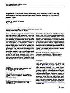
Fig. 1. Framework in development
there, platform independent and dependent code will be generated to create a model executor able to run on specific platforms. Figure 1 illustrates the framework where this contribution will be integrated, on “SysML Model to Petri Net” process. Several others contributions will be done and integrated in this process, creating a very valuable tool to be used on the modeling development process.
4 The Input Output Place Transition Net Class The Input-Output Place Transition class (IOPT) extends place-transition nets with nonautonomous constructs. It is a class of non-autonomous Petri nets in the tradition of interpreted and synchronized Petri nets of Moalla et al. [3], Manuel Silva [5], and David and Alla [4], named Input-Output Place Transition nets (IOPT) and proposed in [6]. IOPT nets get their name from the possibility to explicitly model external input and output events and signals. The events impose an environment dependency on the Petri net model. More specifically, a transition can be fired only if it is enabled and ready. As usually, a transition is enabled depending on the marking of its input places. Yet, it is ready depending on an additional guard defined as a function of external input signals, as well as on input events. Additionally, IOPT nets have a stepwise maximal firing semantics: in each step, all transitions that are enabled and ready are fired. The IOPT syntax and semantics, as well as the respective rationale, were already formally presented in [6]. Compared to place-transition nets, IOPT nets have the following additional characteristics: (1)Input and output events and signals with an edge level for input events; (2) Two types for input and output signal values; (3) Test arcs and arc weights in normal and test arcs; (4) Priorities and input signal guards in transitions; (5) Each transition can have a set of associated input events and a set of associated output events; (6) Each place can have a set of output signal conditional
Towards Statecharts to Input-Output Place Transition Nets Transformations
231
assignments and a bound attribute; (7) An explicit specification for sets of conflicting transitions (conflict sets) and sets of synchronous transitions (synchronous sets). The present work benefits from the results of the FORDESIGN project [4] where a set of tools were developed allowing the use of IOPT nets for code generation from models, namely the following: (1) a graphical editor (including animation capabilities; (2) a tool for the textual specification of model compositions (OPNML2PNML); (3) a tool for the decomposition of an IOPT model into a set of concurrent submodels; (4) translators to C and VHDL, allowing automatic code generation; (5) a configurator (for generating final code considering a specific hardware-software platform). Those tools rely on the PNML interchange format and on Petri net Type definition defined by a Relax NG grammar. Currently, we foresee the use of an Ecore metamodel for the IOPT class, presented in [10], thus offering improved robustness and maintainability, especially for a new generation of code generators.
5 Translating Statecharts to Input Output Place Transition Nets This section presents translations rules to convert statecharts elements into the correspondent Input Output Place Transition Nets items. The proposed translation procedures are based on the analysis of specific situations, through the analysis of specific model characteristics. On the current development stage, only a selected set of statecharts elements are considered: states, transitions, events, guards, action, as well as composite states, as orthogonal states (and-sets) and mutually exclusive states (xor-clusters). Other relevant items for specific modeling situations are not discussed in this paper, namely communication mechanisms, hierarchical structuring, preemption, history mechanisms, and others. Yet, the referred subset of selected characteristics is adequate to model a large number of systems. In the next section, the validation of their application to a specific application is presented. In the following subsections translation techniques for the referred elements are presented. 5.1 Mapping States Statecharts are basically constructed from state diagrams. A state represents a situation or context in a given time instant. States can be classified into simple states (normal state, initial state, or final state), and composite states, which can be of two kinds: the and-set and the xor-cluster. The xor-cluster is a state machine, in the sense that it is composed by a set of states and transitions, where at most one state can be active at a specific point in time. The and-set is the parallel composition of a set of xor-clusters, where all the xor-clusters in the and-set are active or inactive at a specific instant. In this sense, a simple state is a state that does not have any substates and corresponds to the final level of refinement. Composite states are substates that were refined through the decomposition or abstraction process. The and-set is a composite state with one or more regions. A region is simply a container for substates (a state diagram). Concurrent states correspond to states belonging to different regions that are executed concurrently.
232
R. Pais, L. Gomes, and J.P. Barros
A simple statechart state is translated to a simple IOPT place with the same name, or with a new automatic unique name if the initial statechart state does not have one, as illustrated in Figure 2. A
A
(a)
Initial
A
A
(b)
Final
A
A tr_A_Final Final
(c)
Fig. 2. (a) Statechart normal state translation; (b) Statechart initial state translation; (c) Statechart final state translation
Initial states are active the first time the model is run. The initial state is pointing to another state through a transition. This block (initial state + transition + state) will be translated into a Petri Net place marked with a token corresponding to the destination state, as illustrated in Figure 2b. The statechart final state corresponds to a state from which its execution can no longer evolve. After the execution of the state previous to the final state, the system should evolve to a state without further evolutions. Consequently, the final state will be translated to a PN final place, a place without output transitions, as illustrated in Figure 2c. 5.2 Mapping Output Actions Associated to States States can have activities associated with it and internal transitions. Activities can be from one of three types: entry, do, and exit. The entry activity is performed when the state becomes active; the do activity is performed as long as the state is active; the exit activity is performed when leaving the state (which means that the state becomes not active); finally, the internal transitions are events that may occur without causing state changes. At the current stage, only do activities assoA ciated to a state are considered. They will be A [outSignal] /outSignal translated as output signals associated to a place, as illustrated in Figure 3. Translation of entry and exit activities will be part of future Fig. 3. Statechart activity translation work. 5.3 Mapping Transitions A transition is a relationship between two states; upon the firing of a transition the first state will become non active while the second state will become active. Transitions can be classified into simple, join, or fork transition.
Towards Statecharts to Input-Output Place Transition Nets Transformations
233
A simple transition connects a A tr_A_B B A B source state to a target state, and is translated by a Petri Net transition connected by the places that correspond Fig. 4. Statechart Simple Transition translation to source and target states, as illustrated in Figure 4. In the general case, the source and target state of a transition may be at a different level in the state hierarchy. 5.4 Mapping Inputs and Outputs Dependencies Associated with Transitions Transitions are supposed to represent [guard] inEvent actions, which are atomic (not interA B tr_A_B ruptible). A transition can have an inEvent A B [guard] associated triple (a set of input events, outEvent /outEvent a Boolean guard and a set of output actions) “Event[Condition]/Action” where all parts of this triple are Fig. 5. Statechart Transition Events and Guard translation optional. A transition is defined as enabled, if it can be fired. A transition can be fired if its source state is active in the current configuration, its event is present, and its guard is satisfied. When it is fired, the source state is left, the transition actions are executed, and the target state is entered. The technique is illustrated in Figure 5. 5.5 Mapping Orthogonal States Orthogonal states are mapped as states, which mean that each and-set, all composing xor-clusters and associated states are translated into places. Fork vertices serve to split an incoming transition into two or more transitions terminating on orthogonal target vertices (i.e., vertices in different regions of a composite and-set). The segments outgoing from a fork vertex must not have guards or triggers. The technique is illustrated in Figure 6. Join vertices serve to merge several transitions coming from source vertices in different orthogonal regions. The transitions entering a join vertex cannot have guards or triggers. The technique is illustrated in Figure 7.
B
B C
tr_Fork A
A
A
A C
B D
D
D
Fig. 6. Statechart Fork Transition translation
C
B
tr_Join
D
C
Fig. 7. Statechart Join Transition translation
234
R. Pais, L. Gomes, and J.P. Barros
5.6 Mapping Mutually Exclusive States A xor-cluster contains mutually excluB sive states, which are literally like A E embedding a statechart inside a state. D C Two simple situations are considered: when the xor-cluster has no final state, B tr_Join and when the xor-cluster has a final E tr_JoinBC_E state. In both situations both the xorA tr_Fork cluster and associated states are transH lated into places, as before. Starting with C D tr_C_D the former situation, when no final state L is present, the proposed translation techniques, already proposed for states Fig. 8. Statechart and the respective IO Net and transitions, are still valid, and will with Mutually Exclusive States be complemented by a explicit modeling of the outgoing transition which will be replicated for all internal states. The proposed technique is illustrated in Figure 8, where the transition from state B to state E is translated by two transitions (as many as the number of states of the xor-cluster B), referred as tr_Join and tr_JoinBC_E. In order to avoid conflicts, priorities are associated with transitions, as illustrated in the IOPT net in the bottom of Figure 8.
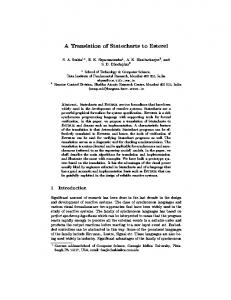
6 A Case Study To illustrate the transformation Left from statecharts to IOPT Nets, the Right example of the controller for a simple Railway System is used. GateUp, GateDown This example includes a scenario Gate Arm where there is a crossing of a Opened, Closed railway line, allowing the movement of trains in both directions (one direction at a time), with a highway motor vehicles and a gate, which allows crossing isolaFig. 9. Railway System tion when the train is passing. The system is shown in Figure 9. The statechart model is presented in Figure 10 and the respective IOPT net model in Figure 11. The initial state of the system admits that the railway line is clear and that the gate arm is open.
7 Conclusions and Future Work We have presented a proposal for the translation from statecharts to a class of nonautonomous Petri nets, the IOPT nets. This class of nets is able to model external input and output signals and events, thus allowing the alternative use of Petri nets. Besides the Petri nets known advantages, the IOPT nets allow the use of modular
Towards Statecharts to Input-Output Place Transition Nets Transformations
Left Entry WaintingLeft
t1
t3
Right Entry WaintingRight
EnteringLeft
LeavingRight
t6
t4
EnteringRight
LeavingLeft t2
Gate Arm
t5
OpenedGateArm t7
t10 GoingUp
GoingDown
t11
/a2
t12
/a1
ClosedGateArm
235
Legend: LeftTrainEntry [not in(GoingDown) and t1 not in(ClosedGateArm)] / CloseGateArm t2 RightTrainEntry t3 RightTrainExit / OpenGateArm t4 RightTrainEntry [not in(GoingDown) and not in(ClosedGateArm)] / CloseGateArm t5 LeftTrainEntry t6 LeftTrainExit / OpenGateArm t7 CloseGateArm / GateLampTurnOn t8 [true(GateArmDown)] t9 OpenGateArm t10 [true(GateArmUp)] / GateLampTurnOff t11 OpenGateArm t12 CloseGateArm a1 GateArmEngineClosing a2 GateArmEngineOpening
t8
t9
Fig. 10. Railway System Statechart [not in(GateArmClosing) and not in(GateArmDown)] LeftTrainEntry WaitingLeft EnteringLeft t1 CloseGateArm RightTrain RightTrain t3 Entry Exit LeavingRight t2 OpenGateArm
[not in(GateArmClosing) and not in(GateArmDown)] RightTrainEntry WaitingRight EnteringRight t4 LeftTrain CloseGateArm LeftTrain t6 Entry Exit LeavingLeft t5 OpenGateArm
CloseGateArm OpenedGateArm [true(GateArmUp)] t10 t7 OpenGateArm GateLampTurnOff GateLampTurnOn t11 [GateArm [GateArm CloseGateArm EngineClosing] EngineOpening] GoingDown GoingUp OpenGateArm t12 t8 [true(GateArmDown)] t9 ClosedGateArm
Fig. 11. Petri Nets corresponding to each of the three subcharts in Figure 10
constructs and can be used as an interchange format among a set of tools. The IOPT Ecore metamodel introduces IOPT nets in the MDA infrastructure, allowing MOF simulation. Hence, it becomes possible to interchange data between IOPT tools and other MDA tools by reusing the associated XMI representation, and to support automatic code generators and the exploration of the automatic proofs of behavioral equivalence between two models, using successive transformations (bidirectional transformations) and its simulation.
236
R. Pais, L. Gomes, and J.P. Barros
References 1. Engels, G.: Keynote: Automatic generation of behavioral code - too ambitious or even unwanted?, Behaviour Modelling in Model Driven Architecture. In: Proceedings of First European Workshop on Behaviour Modelling in Model Driven Architecture (BM-MDA), Enschede, The Netherlands, June 23 (2009) 2. Harel, D.: Statecharts: A visual formalism for complex systems. Science of Computer Programming 8(3), 231–274 (1987) 3. Moalla, M., Pulou, J., Sifakis, J.: Synchronized Petri nets: A model for the description of non-autonomous systems. In: Winkowski, J. (ed.) MFCS 1978. LNCS, vol. 64, Springer, Heidelberg (1978) 4. David, R., Alla, H.: Petri Nets & Grafcet; Tools for Modelling Discrete Event Systems. Prentice Hall International, UK (1992) 5. Silva, M.: Las Redes de Petri: en la Automática y la Informática. Edit. AC, Madrid (1985) 6. Gomes, L., Barros, J., Costa, A., Nunes, R.: The Input-Output Place-Transition Petri Net Class and Associated Tools. In: Proceedings of the 5th IEEE International Conference on Industrial Informatics, INDIN 2007 (2007) 7. de Lara, J., Vangheluwe, H.: Computer Aided Multi-Paradigm Modelling to Process Petri-Nets and Statecharts. In: Corradini, A., Ehrig, H., Kreowski, H.-J., Rozenberg, G. (eds.) ICGT 2002. LNCS, vol. 2505, pp. 239–253. Springer, Heidelberg (2002) 8. Carneiro, E., Maciel, P., et al.: Mapping SysML State Machine Diagram to Time Petri Net for Analysis and Verification of Embedded Real-Time Systems with Energy Constraints. In: Proceedings of the 2008 International Conference on Advances in Electronics and Micro-Electronics, pp. 1–6 (2008) ISBN:978-0-7695-3370-4 9. Gomes, L.: As Redes de Petri Reactivas e Hierárquicas - integração de formalismos no projecto de sistemas reactivos de tempo-real (in Portuguese); PhD Thesis, UNL-FCT (1997), http://hdl.handle.net/10362/2560 10. Moutinho, F., Gomes, L., Ramalho, F., Figueiredo, J., Barros, J.P., Barbosa, P., Pais, R., Costa, A.: Ecore Representation for Extending PNML for Input-Output Place-Transition Nets. In: 36th Annual Conference of the IEEE Industrial Electronics Society, IECON 2010, Phoenix, AZ, USA, November 7-10 (2010) 11. Sandborn, P., Myers, J.: Designing Engineering Systems for Sustainability, CALCE, Department of Mechanical Engineering. University of Maryland, http://www.enme.umd.edu/ESCML/Papers/SustainmentChapter.pdf