to the development of the display concept. .... In developing the concept and the proof-of-concept .... Both IDL and ENVI allow cross-platform development.
TOWARDS THE DEVELOPMENT OF MULTISENSOR INTEGRATED DISPLAY SYSTEMS A. L. Drozd, C. E. Carroll, Jr. and I. Kasperovich ANDRO Consulting Services, Beeches Technical Campus, Rome, NY 13440
P. K. Varshney and D. D. Weiner EECS Department Syracuse University, Syracuse, NY 13244
Abstract-C4 I surveillance system operators and air defense crews encounter ever-increasing amounts and types of real time information from both on- and offboard sensors and other information sources. These growing demands place undue information processing requirements on operators and aircrews that can lead to information overload. As a result, operators are forced to function as human data integrators rather than as decision makers. One solution is to provide operators a common set of display formats that present data in a highly intuitive and readily useable form mimicking human visual perception processes. This paper discusses the findings of exploratory research to develop a novel display concept called iTimeCop (Integrated Target Image Expressed in a Common Operating Picture) which is intended to provide an integrated picture of multi-disciplinary and multi-sensor (MD/MS) data within a common display environment. The technical research described in this paper was sponsored under US Air Force Contract F30602-00-C-0112 for the Air Force Research Laboratory Information Directorate, Rome Research Site. Keywords: Information Fusion, Multi-Sensor Fusion, Integrated Display, Visualization, Information Management Tools, Common Operating Picture, Situation Awareness
1.
Introduction
The MD/MS information fusion problem for C4 I system operator scenarios is complicated by the increasing number of off-board military platforms providing situation awareness data on many different tracks and targets, and the assessment of sensor fusion data from multiple sources. The data provided might be real time, near real time, or non real time based. Today’s humanmachine interfaces (HMIs) are often the bottleneck in effectively and efficiently utilizing the available information flow for decision making. This is increasingly true with the advancements in processing speeds and throughput. New capabilities must be developed to visualize and interact with information in order to provide an integrated situation awareness picture to the operator or crew. The iTimeCop concept represents a new approach for presenting an integrated picture of MD/MS data using a
M. G. Alford Air Force Research Laboratory/IFEA 32 Brooks Road, Rome, NY 13441-4114
common operating environment. As the name suggests, a capability is provided to automatically “survey” or keep track of displayed sensor data and monitor dynamic targets/tracks using range Doppler plane metrics expressed as a function of vector position and time. This is accomplished iteratively by superimposing sets of static sensor data in an integrated picture context collected over a number of time slices, or by using near real time recorded sensor data. The concept presents an integrated 4-D picture of the scene, where the fourth dimension is time, using processed data from multiple sensors and sources. It is adaptable to a variety of computer display hardware and accounts for the use of alternative pointing and multi-modal input devices to optimize human-machine interaction. Fundamentally, the display scheme allows for multiple scene overlay and rendering, data registration and integration, and target-object identification while computing target uncertainty. Cognitive techniques can be applied to assess the degree of uncertainty. Targets are represented as simplified object icons that are assigned both visual and audible cues and implicit attributes describing their nature (friendly, hostile), certainty level, range Doppler characteristics, and other properties. These act as logical guides to quickly orient the operator to the target scenario. Visualizing uncertainty and optimization of the HCI factors are key to the development of the display concept. Additionally, the display system must be readily useable by a ground operator, air crew, battlespace commander, or cockpit warfighter across various computing and display platforms with little or no training. This paper discusses several issues related to integrated display design for situation awareness and describes a prototype developed for this purpose.
2. Display system concept design The fundamental display design includes considerations for user-oriented display formats, automated and manual data drill-down concepts, operator-machine interface concepts (including various pointing and user control devices), data source analysis, connectivity, target identification evaluation concepts, and data integration
concepts. The concept involves a novel application of target object abstraction and representation techniques using a combination of colors, icons, glyphs, and animation and other visual aids to quickly direct the operator’s attention to the high-probability target(s) of concern. User controls allow the operator to “manipulate” or “interrogate” the scene to: (a) obtain characteristics on target(s) displayed within the integrated, composite, or sensor fused data layer or from constituent MD/MS layers; (b) ascertain the nature of targets (friendly, hostile), associated range Doppler plane parameters including uncertainty, source of the data, and other useful properties; (c) selectively overlay data sets, perform zoom-ins and fly-throughs, or obtain perspective views of the target area of interest; and (d) reason on the uncertainty aspects of the data and determine how data should be displayed using cognitive techniques or by applying artificial intelligence (AI) methods.
2.1 Common operating picture Creation of a detailed, timely and accurate picture of the modern battlespace is vital to the success of C4 I operations. This picture is used to make strategic decisions such as movement of assets and materials, and decisions to attack. Most modern command operations centers (COCs) employ a wide variety of systems that provide multi-disciplinary information from many different sources such as eye witness reports, aerial photographs, sonar, radar, SAR, multi-spectral imaging (MSI), hyper spectral imaging (HSI), foliage penetration radar (FOPEN), electro-optic (EO), IR and MTI data. These disparate and sometimes conflicting sources must be combined to develop a common operating picture (COP). The quantity of information is so large that it is almost impossible for a single individual to collect, analyze, and comprehend all the information. Typically, each information source is analyzed separately by a trained operator. This processed information is fused to create a COP. If this picture contained all the information that has been collected in a nearly raw form, the decision-maker would be subject to information overload. The goal is to obtain a clear, concise, coherent, complete, timely and accurate picture of the battlespace. In addition, this picture needs to be presented in an easy to understand and usable form so that the decision-maker can make sound choices based on information acquired from the multitude of information sources. If possible, this picture should also provide a risk analysis associated with different possible actions. Thus, it is imperative that automated methods and tools be developed to acquire, process, fuse, and display an integrated battlespace picture that makes it easier for C4 I decision makers to carry out their assigned
tasks. The idea is to present a common picture of the target scene, but allow the information and data to be presented differently based on the individual operator’s needs. Another important issue that has largely been ignored namely that of uncertainty, must be addressed. A key goal is the computation of uncertainty associated with integrated or fused data and its presentation in a visually intuitive way without cluttering or information overload. The extent of the general problem of data visualization and display is quite vast and depends upon the application scenario. Multiple wall screens and sand table displays are appropriate for command center facilities where a large amount of data needs to be presented in a comprehensible and coordinated manner. At the other end of the spectrum is a mobile user with a lightweight Personal Digital Assistant (PDA), a Head Mounted Display (HMD), or a Head-Up Display (HUD). In the research, a display design concept was developed with a commercial desktop workstation in mind. However, considerations were given to other types of display and pointing or control devices. It is expected that this research will also have applicability to other scenarios such as at a command center or for a mobile user.
2.2 Display system framework, algorithms and utilities The research investigated novel methods for registration, fusion, uncertainty representation and computation, information utility analysis for operators, user behavior and reaction modeling and evaluation, and HMI factors. The goal was to ensure that the design of the information portrayal algorithms matches the perceptual and information processing characteristics of the operator. The research centered on five key areas: (1) the customized HMI and use of multi-modal control and pointing devices, (2) computation and visual indication of target uncertainty, (3) symbolic representation of targets and assignment of attributes or properties, (4) interface design for relatively seamless and efficient data flow to/from the display environment, and (5) providing for powerful, but easy to use drill-down methods to interrogate target data and data layers. In developing the concept and the proof-of-concept capability, considerations were given to implementing novel and efficient methods for data processing (model construction, registration, image analysis tools, and data fusion), database design, display design (application of visualization tools and HMI optimization principles), and uncertainty computation and visualization. The references contain details on specific applications of: data processing methods; model construction;
registration algorithms; and image analysis for multimodality image data [1]; various levels of information fusion (data-level fusion, feature-level fusion, and decision-level fusion) [2-4]; and using animation, color and other methods to present uncertainty [5].Uncertainty computation and visualization issues are being investigated in a DoD sponsored MURI program [5] that is aimed at developing the methodologies and tools required for the design and analysis of time-critical visualization systems under uncertainty, using augmented reality and 4-D dynamic models of the environment. There are three major aspects of uncertainty visualization and display: computation of uncertainty, fusing of information, and visualizing uncertainty. The challenge in an integrated C4 I display system is to combine the uncertainty modeling concepts from different domains to create a common consistent representation of uncertainty. This poses new challenges in modeling and managing uncertainty that have not been addressed. The next component is the fusion and assimilation of information along with uncertainty from multiple sources in distributed mobile networks for decisionmaking. Considerable work on information and data fusion has been done by one of the authors with focus on specific tasks such as target detection and recognition problems under different optimization criteria; however, without considering the associated uncertainty. Clearly, fusion methodology that takes various forms of uncertainties into account needs to be developed. Once a common consistent representation of uncertainty is computed over the distributed mobile network, the major challenge of visualizing and displaying uncertainty in a C4 I visualization system still remains.
sound) presentation of information to the user in an unobtrusive and intuitive way must also be considered. Another approach for uncertainty representation by means of different icons representing a range of possibilities has been followed in [7]. This approach will also be further examined for possible adoption.
2.2 User behavior modeling, display optimization and HMI best practices In an interactive decision making environment, human decision-makers need to be supported during the entire decision-making process (problem identification, alternative formulation and evaluation, and solution execution). Different stages in a decision-making process may require the decision-makers to comprehend different types of data/information (such as at different abstract levels) in different formats. Thus understanding the kind of decision tasks would be of great importance to achieve a better cognitive fit between the tasks and the displays of the appropriate data/information. There are two models which have been shown to be appropriate for the study of behavior towards new computing technologies: Theory of Reasoned Action (TRA) and the Technology Acceptance Model (TAM). The TRA model is derived from attitude theory and was proposed by Ajzen and Fishbein [8]. The TAM model, introduced by Davis [9], was specifically designed to explain comp uter usage behavior. Several studies [9] have shown that TAM is indeed an appropriate modeling tool for examining the user's behavior towards new computing technology. In developing the concept, certain display techniques and proven HMI methods were applied to optimize the way information is presented to operators on multifunctional displays to enhance situation awareness. These practices included:
Research has been done to investigate a host of methods including deformation, texture mapping, glyph mapping, transparency mapping, animation, highlighting, topology mapping and sonification (use of non-speech sound) to visualize uncertainty in an 1. Identify display optimization requirements. In effect, the display must be designed to fit the user(s), their integrated manner with the scientific data [6]. The application(s), and situation(s). battlespace visualization system presents a more complex time-critical decision making scenario. The 2. Define and design the physical characteristics of experience in [6] dictates that depending upon the display that are necessary and not extraneous. This display device and the task, different techniques of principle addresses the various user options from an uncertainty mapping need to be employed. For instance, HMI perspective including the size and placement of object deformation is useful in target aiming, where the buttons/controls, text, etc.; the design information object is deformed both in time and space in the hierarchy (i.e., the display “presentation” including direction where the object is more likely to be located. In establishing relationships, categories, and naming topology mapping, the terrain is presented as an outline conventions among buttons/controls); and the actual of critical features of the terrain connected with hills and implementation of these guidelines to achieve a valleys of the region with lines. This method reduces necessary and sufficient display scheme. clutter and allows available screen space to be utilized to 3. Recast the design effort as an optimization problem. show occluded objects as icons or glyphs in an This involves converting the design guidelines to augmented reality view. Multi-modal (using vision and
cost, where the best design translates into minimum implementation and maintenance costs. There are available software metrics tools that can be used to achieve the desired design feature-cost balance, for example, the Multi-Functional Design (MFD) tool.
that if we do not know “what” or “when”, we (conservatively) tend to expect the worse outcome. In other words, it is human nature to relate higher hazard levels or “danger” to distorted images.
4. Judiciously implement special functions or capabilities that perform highly desirable tasks. For example, cognitive tools and techniques can be inserted to optimize the selection of one or more sensor data layers, and to retrieve specific contact or drill-down information.
Spheres can be used to symbolize the 3-D locations of aircraft or ground targets. Larger or exaggerated spheres can show “indefinite” space of an aircraft indicating an uncertainty level. Smaller spheres can show more exact locations with high confidence in data. However, large glyphs tend to make the user perceive a large threat. Adding in opacity with high contrast for higher confidence and more definition of location or adding in transparency with low contrast for lower confidence and less definition of location offers a possible solution.
Visualizing uncertainty is essential. There are different ways to express uncertainty. For example, a percentage value refers to how sure we are of a target’s probability. Range refers to a bounded interval within which the value falls. Error is expressed in various ways as well. Some error computations are based on raw data and the methods used to acquire such data. Other error estimates are based on the degree of accuracy of analyses and mathematical transformations. Yet other error estimates are attributed to the way data or results are presented, or on the quality of graphics used to convey res ults. The goal is to develop a means to visualize the uncertainty with a very high degree of confidence in a quantifiable manner. Icons are traditional ways of visualizing real world objects, uncertainty or probability, processes or even situations. Glyphs, on the other hand, are graphic objects that encode information through shape, color, size, text, light source, motion, and other descriptive attributes [10]. For instance, custom glyphs can be used to show target type as well as inform the operator of position, direction and speed of movement, nature (friend or foe), relevant lethality parameters, and its degree of certainty or probability. There are numerous representations and forms of objects, glyphs, or icons that can be used to illustrate the dynamics of a target including its uncertainty level. “Uncertainty ribbons” are examples of glyphs that show the degree of positional and trajectory uncertainty expressed via changes in size, color density, or extent in three dimensions. Consider the example of FOF (friend or foe). FOF can been visualized as a “happy face” or “sad face” at the extreme ends of the spectrum with blurred, hazy, or neutral dispositions when certainty about the target is not fully known [11]. The American flag verses a skull and crossbones symbol is another FOF motif. Examples of the use of these symbols are shown in Figures 1 and 2. Of course, there are also classes of neutral objects, which differ from unknown objects, that do not fall into this range. Studies support the conclusion that the operator or pilot might view a blurred image more likely as foe than anything else. Human nature demonstrates
Blinking, or continuously changing size (e.g., pulsation), or both can be used to show the degree of confidence or immediacy of the threat, which could be contradictory depending upon how such animation is used. Other possible glyphs include squares for 2-D space, lines for range, or placing spheres on ends of lines or tracks, or placing circles intermittently throughout each track line [12].
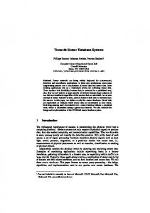
3 Application of display tools for MD/MS scenarios Several commercial tools and government utilities were integrated to establish a basic capability. A display environment was established that provides for varying levels of detail in order to enhance its utility for rapid target identification and assessment. This is illustrated in Figure 1.
3.1 Core Display Software and Support Utilities A proof of concept capability was developed using a combination of JView developed by the Air Force Research Laboratory [13] and the Environment for Visualizing Images (ENVI) produced by KodakResearch Systems, Inc. JView exploits the power and speed of Java 3-D for scene generation and for animated target rendering. It is a 3-D, runtime configurable and platform independent visualization program and API. It is written entirely in Java and utilizes the Java 3-D API to gain hardware graphics acceleration. JView relies on concrete ObjectOriented Design and Programming techniques to provide a robust and venue non-specific visualization environment. There are three types of modules that are created for this application. There are venue specific modules called facilitators that conquer the specific task
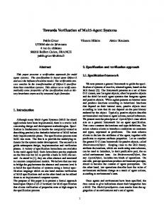
of placing objects in the scene and manipulating their behavior. The second type are plug-ins that are venue non-specific and add general functionality to the system. The last type consists of data source loaders called oddments. By creating these three classes of modules, we can quickly conquer the often arduous task of creating a tailored visualization system. JView is our current solution to representing a rapidly changing real world environment. The task of analysis and visualization extends over a diverse heterogeneous environment varying in computing platform, operating system and capabilities. The JView tool is completely data source independent. Facilitators can be written to visualize data from various data sources including simulation audit trails, live radar simulations, synthetic entities, or hardware in the loop feeds. One of the key features is its ability to run multiple facilitators simultaneously. This allows the user to ocularly fuse information that can reside in varied modes of storage and persistence. By definition, JView is a Standard Visualization Solution since it does not concentrate solely on space, air, ground or water genre. When a new data type becomes available and visualization is necessary, JView allows the programmer to quickly implement the additions. It also allows the analyst to operate in an environment in which they are familiar, instead of having to learn a new interface. JView provides another important advantage, that is, it exploits the power of Java 3-D, one of our other preferred development languages for graphics applications. Figure 2 shows examples of JView’s environment to display generated scenes using actual map and simulated air target and moving ground vehicle data.ENVI is a remote sensing, hyperspectral, data analysis and visualization tool that was written in the Interactive Data Language (IDL). IDL package can be used to program the visualization routines as well as the routines that will reason on incoming data. ENVI provides the graphical user interface (GUI) for IDL. Both IDL and ENVI allow cross-platform development permitting the programmer to build and maintain the software over different types of user systems. An illustration using ENVI and IDL for terrain cases is shown in Figure 3.
3.2 User pointing devices, operator controls and modalities The traditional keyboard/mouse approach, though popular, can restrict information flow between the user and the computer system, and ultimately to the aircraft or plant under control. Information rich environments require an operator-centered approach that adapts to heterogeneous changing connections of information sources and devices with multiple modalities. Multimodal environments must possess the capability of being interoperable. These environments may include such modalities as: gesture/speech recognition, eye gaze, lip reading and even biofeedback mechanisms attached to the crewmembers themselves. The integration of multimodal inputs for human machine interaction can be approached from the viewpoint of multiple information source fusion. Different information sources can be related to different interface modalities. Selection of the appropriate modalities to integrate and at what level to integrate them is part of the process of developing an interoperable multi-disciplinary situational awareness fusion system. In this concept, traditional analog instruments and gauges would be replaced with large flat-panel multi-function displays that combine the functions of separate instruments into a multi-function workstation. A new digital operator control center or cockpit would provide operators and pilots with equipment that is more intuitive, easier to use, and less expensive than today’s avionics equipment. To that end, a number of display pointing device options were considered including: joystick, light pen, electronic finger glove, electronic hand glove, gaze control (eye or head movement), look and speak capability (“show me…”), point & speak (“move here”), rubber band selection of a scene using a marquis tool, wireless handheld PC, visual speech recognition, throat microphone, wireless wearable computer and 3-D display (augmented reality), and multi-modal bio-feedback devices. Ancillary devices include display stabilization frames and methods to tie pointing devices into reports of confidence scores to compute target uncertainty and associated parameters during.
(a) (b) (c) Figure 1: Digitized Terrain Battlespace Scene: (a) Detailed View, (b) Mesh View, (c) Outline View
3.3 Illustration of operator user scenarios This discussion highlights some of the techniques and procedures used in the target scene generation, test and evaluation, and validation of scenarios using integrated MD/MS data. First, the operator will have the ability to read in and view a terrain map or an aerial scene. Examples of visual displays of aerial scenes and terrain maps using JView and ENVI were shown in Figures 2 and 5. The terrain map will need to be presented as a 3D object in which rotation, zoom, and scale, are among the operations to be performed. The importance of this is seen when researching the “sky-scan” or “airspace viewing” capability where a user will not only want to locate possible threats or targets on the ground, but also in the airspace above the terrain of interest. An important aspect here is a panoramic viewing camera within the system. Using this camera, the operator will have the option to choose terrain or airspace viewing based on the pointing direction of the camera.
The second type of layer pertains to roads, cities, buildings, and landmarks being placed on the terrain or combined as one layer on top of the terrain display. Techniques can be applied to reduce visual “clutter” or any other visual hindrance to the operator through the use of image processing and abstraction techniques. The next type of layer is created by overlaying the terrain map, for instance, with the composite, integrated layer that is generated from the data collected from multiple sensors. This layer will contain information regarding possible targets, threats, the uncertainty levels for each, entity (user, threat, target, etc.) positions, and directional information. Display optimization techniques and effective visualization options will be considered in order to efficiently communicate information to the operator. For example, JView provides an excellent basis for customizing and optimizing a display capability for this purpose.
(a) (b) (c) Figure 2. JView Display Environment and User Control Panel for (a) Air Targets Over Geographical Terrain, (b) Scene Manipulation (Target Homing), (c) Air Tracks and Traffic Corridors or Flight Paths
Figure 3. Illustrating ENVI/IDL Terrain Maps, Zoom Capabilities and Methods to Obtain Information on Displayed MD/MD Targets
From a large-scale terrain map that covers a wide area, target entities can be represented as blinking dots. The color of the dot would represent friend or foe to the user and the rate of blinking would represent the certainty level of the target. The operator can do one of two things in response to this. First, he can click on the dot to obtain textual information about the target entity. This information will be presented to the user through the use of a small window or dialog box that will pop up on the screen next to the dot. The other option that the user has is to zoom in on the terrain map using a pointing device or user controls. Discussions are currently taking place that will lead to the best possible pointing device options (touch pen, track ball, mouse, keyboard commands, keyboard button press, finger glove, eye gaze, head movement, voice commands, etc.) and view manipulation (zoom using a click box, keyboard buttons, view scale percentages, voice-controlled operations, etc.). If the user zooms in on the target or a subregion of the scene, depending on the percentage of the zoom, the view may still contain the same format as the initial large-scale map. When the user is at a pre-defined view camera distance, the visual format of the layer will change slightly in order to provide the most efficient analysis from the viewpoint of the operator. Instead of blinking dots, more interpretive icons can be applied. Also at this view distance, uncertainty levels can be represented visually rather than by text alone, as in previous view distances. Methods of visualizing uncertainty can be accomplished using glyphs that can dynamically “morph” as the state of the target object or scene changes over time and/or in order to quickly get the operator’s attention to the target and its intentions. This is accomplished through the application of color changes within an entity, entity animation, and varying “fuzziness” or sharpness to the entity represented by the glyph. Methods for adding geometry, modifying geometry, changing attributes, applying animation, and sonification can also be used. A single glyph works well alone, but one or more groups of a single type of glyph clustered together may be inefficient. One type of animation expressed as a blinking icon would alert the operator of immediate “danger” or that no problem exists. Intermittency might also inadvertently suggest a lower level of confidence in the data. Another possible display scheme that has been studied is a color-density mosaic map which can be used to rapidly focus the operator’s attention to “hot” and “cold” spots in the displayed scene. The operator can drill down to obtain detailed data parameters or characteristics. Drill down methods were researched for cluster views involving many groups of overlapping objects displayed on a screen. Consider, for example, a ground station
(e.g., an air base with targets) elevated well above sea level and some distance away as represented within the view frame. This adds various complexities to the 3-D viewing problem in terms of the large area, relative distances or proximities, clustering of targets, elevation, and so on. Graphically displaying this station, rendered to scale, would result in the targets and other objects in the problem to not be readily visible. For instance, if the target base were twenty miles away, when scaled to the total screen size of a display, the targets and other objects would appear as very small dots. This might lend to operator confusion due to the insufficient resolution of the display. One solution is to render the smaller objects as artificially larger objects. However, distinct objects that are closely spaced with respect to each other will then appear clustered resulting in a masking problem and an inability to properly access certain objects. Drill-down solves this dilemma by affording the user with a zoom-like function. By double-clicking on an object, the view is redrawn as a complete visualization of only the entities in close proximity to the object selected. In this case, the entities are redrawn to scale. This drilling down procedure can be performed incrementally, if so desired. In much the same manner, a possible battlefield display for a pilot could include viewing an aircraft sixty miles away on the horizon, for example. When drawn to scale, the aircraft looks like a small dot with no clear features that can be used to discern what type of aircraft it is, let alone whether it is friend, foe or neutral. The display could render distant aircraft targets larger than to scale, thus changing the small dot on the display to a larger object that can be readily noticed and recognized. However, if there are several similar aircraft targets in the same part of the sky view, then the display will be clustered; consequently, the pilot will not be able to distinguish between the aircrafts. Drilling down on the cluster and rendering only that part of the sky view will allow for true-to-scale visualization where entities will be large enough in order to identify important details and to distinguish one target from another. Depending upon the display device and operator task, different algorithms and techniques can be used to convey uncertainty. The idea is to present and convey uncertainty information in an intuitive, uncluttered manner to the operator. In general, this can involve object deformation (i.e., target “aiming” in time and space in the direction where the object is more likely to be located or “migrate” towards); texture mapping; glyph mapping; transparency mapping (i.e., where objects with high confidence appear solid as opposed to objects with low confidence that appear more transparent or ephemeral); animation; highlighting; topology mapping (i.e., presenting an outline of the
critical features of a target scene which reduces clutter and allows available screen space to be utilized to show occluded objects as icons or glyphs in an augmented reality view); sonification (use of non-speech sound); multi-modal presentation of information to the user (using vision and sound); and use of different icons to represent a range of possibilities.
[2] D. Hall and J. Llinas, “ An Introduction to Multisensor Data Fusion,” Proc. Of the IEEE, pp. 6-23, Jan. 1997.
4 SUMMARY
[4] P. K. Varshney, Distributed Detection and Data Fusion, Springer-Verlag, 1997.
Exploratory research has led to the identification of design concepts and techniques for developing a next generation 4-D visualization/display component for future military and commercial information management systems. In the case of military applications, the findings address identifiable infrastructure needs consistent with the Integrated C2 and Joint Battlespace Infosphere (JBI) concepts [14]. The JBI is connected to, and interoperable with, a variety of C2 and combat support information systems such as AWACS and Joint STARS. Such an advanced visualization/display tool can convert complex MD/MS data into usable knowledge (situation awareness) to support the JBI and integrated C2 goals for “digitally” assessing the battlespace situation. The ability to incorporate large amounts of electronic flight information that can be managed with great ease and minimal training has the potential of revolutionizing the general aviation sector. Safe and effective control has implications in other control room and control station scenarios including the operating room of a hospital, building management and safety, nuclear power plants, emergency and life support services, and the interactive workplace of the future. The algorithms and visual techniques are also applicable to any commercial industry that evaluates large amounts of data from real-time to historical data in order to determine the current state of the environment and analyze or forecast future trends.
Acknowledgments The authors wish to acknowledge Jason A. Moore and Chad F. Salisbury of the Air Force Research Laboratory/IFSB, Rome Research Site and Kurt V. Sunderland of Logicon, Inc. in Rome, NY for their technical support and assistance on behalf of this research and development.
References [1] P. K. Varshney et al., “ Registration and Classification of Multi-modality Imagery,” Proc. of the Kodak MMIFS Conf., Oct. 1999.
[3] P. K. Varshney, “ Multisensor Data Fusion,” Electronics and Communications Engineering Journal, pp. 245-253, Dec. 1997.
[5] http//wwwvideo.eecs.berkeley.edu/vismuri/murindex.html. [6] Pang et al., “ Approaches to Uncertainty isualization,” The Visual Computer, pp. 370-390, 1997. [7] Bisantz, J. Llinas et al., “ Human Performance and Data Fusion Based Decision Aids,” Proc. Fusion’99. [8] I. Ajzen and M. Fishbein. Understanding attitudes and predicting social behavior. Englewood Cliffs, NJ, Prentice-Hall, 1980. [9] F. D. Davis. A Technology Acceptance Model for Empirically Testing New End-user Information Systems: Theory and Results. Doctoral dissertation, MIT Sloan School of Management, Cambridge, MA, 1986. [10] E. Blasch, "Assembling a Distributed Fused Information-Based Human-Computer Cognitive Decision Making Tool", Proc. IEEE AES Systems Magazine, May 2000. [11] M. Bisantz, R. Finger, Y. Seong, J. Llinas "Human Performance and Data Fusion Based Decision Aids", Proc. Fusion '99. [12] S. K. Lodha, A. Pang et al., "UFLOW: Visualizing Uncertainty in Fluid Flow", http://www.cse.ucsc.edu/research/slvg/uflow.html. [13] C. F. Salisbury, S D. Farr, and J. A. Moore, ‘Webbased Simulation Visualization Using Java3D”, Webbased Simulation I: 1999 Winter Simulation Conference Proceedings, 5-8 December 1999, Ed. P.A, Farrington, et.al. [14] US Air Force Scientific Advisory Board “Summary Report on Building the Joint Battelspace Infosphere”, Vol. 1, SAB-TR-99-02, 17 December 1999.