semantics are satisfied for a small number of sender and receiver components. ..... some paths the relevant Sender or Receiver never reaches the return label.
Towards Verifying Correctness of Wireless Sensor Network Applications using Insense and Spin O. Sharma1 , J. Lewis2 , A. Miller1 , A. Dearle2 , D. Balasubramaniam2 , R. Morrison2 , and J. Sventek1 1
Department of Computing Science, University of Glasgow, Scotland School of Computer Science, University of St. Andrews, Scotland
2
Abstract. The design and implementation of wireless sensor network applications often require domain experts, who may lack expertise in software engineering, to produce resource-constrained, concurrent, real-time software without the support of high-level software engineering facilities. The Insense language aims to address this mismatch by allowing the complexities of synchronisation, memory management and event-driven programming to be borne by the language implementation rather than by the programmer. The main contribution of this paper is an initial step towards verifying the correctness of WSN applications with a focus on concurrency. We model part of the synchronisation mechanism of the Insense language implementation using Promela constructs and verify its correctness using SPIN. We demonstrate how a previously published version of the mechanism is shown to be incorrect by SPIN, and give complete verification results for the revised mechanism.
Keywords Promela; SPIN; Concurrency; Distributed systems; Formal Modelling; Wireless Sensor Networks
1
Introduction
The coupling between software and hardware in the design and implementation of wireless sensor network (WSN) applications, driven by time, power and space constraints, often results in ad-hoc, platform specific software. Domain experts are expected to produce complex, concurrent, real-time and resource-constrained applications without the support of high-level software engineering facilities. To address this mismatch, the Insense language [3, 10] abstracts over the complexities of memory management, concurrency control and synchronisation and decouples the application software from the operating system and the hardware. An Insense application is modelled as a composition of active components that communicate via typed, directional, synchronous channels. Components are single threaded and stateful but do not share state, thereby avoiding race conditions. Thus, the complexity of concurrent programming in Insense is borne
by the language implementation rather than by the programmer. Verifying the correctness of Insense applications requires that the language implementation be proved correct with respect to its defined semantics. The main contribution of this paper is an initial step towards verifying the correctness of WSN applications by modelling the semantics of Insense using Promela constructs. We focus here on concurrent programming and in particular on the correctness of the Insense channel implementation. The Insense channels and some of their associated algorithms are modelled in Promela. SPIN is then used to verify a set of sufficient conditions under which the Insense channel semantics are satisfied for a small number of sender and receiver components. The remainder of this paper is structured as follows. Section 2 provides background information on WSNs, Insense, and model checking. We then present the Insense channel model and its implementation in sections 3 and 4 respectively. Section 5 details the translation of the Insense channel implementation to Promela, develops a set of properties to verify the correctness of the implementation and demonstrates how a previously published version of the channel algorithms is shown to be incorrect by SPIN. Section 6 presents complete verification results for a revised set of algorithms and for previously unpublished connect and disconnect algorithms. Section 7 includes conclusions and some thoughts and directions on future work.
2 2.1
Background Wireless Sensor Networks
WSNs, in general, and wireless environmental sensor networks, in particular, are receiving substantial research focus due to their potential importance to society [1]. By composing inexpensive, battery-powered, resource-constrained computation platforms equipped with short range radios, one can assemble networks of sensors targeted at a variety of tasks – e.g. monitoring air or water pollution [15], tracking movement of autonomous entities (automobiles [20], wild animals [22]), and attentiveness to potentially disastrous natural situations (magma flows indicative of imminent volcanic eruptions [23]). A wireless sensor node is an example of a traditional embedded system, in that it is programmed for a single, particular purpose, and is tightly integrated with the environment in which it is placed. As with all embedded computer systems, it is essential that appropriate design and construction tools and methodologies be used to eliminate application errors in deployed systems. Additionally, a wireless sensor node is usually constrained in a number of important operating dimensions: a) it is usually battery-powered and placed in a relatively inaccessible location; thus there is a need to maximize the useful lifetime of each node to minimize visits to the node in situ to replace batteries; b) the processing power and memory available to each node are severely constrained, therefore forcing the use of cycle-efficient and memory-efficient programming techniques; and c) the range of a node’s radio is limited, thus potentially forcing each node to act as a forwarding agent for packets from neighbouring nodes.
A typical application operating on a WSN system consists of code to: take measurements (either at regular intervals or when an application-specific event occurs), forward these measurements to one or more sink nodes, and subsequently to communicate these measurements from the sink node(s) to a data centre. In order to design such an application, a variant of the following methodology is used: – A domain expert (e.g. hydrologist), using information obtained from a site visit and topological maps, determines the exact locations at which sensors should be placed (e.g. at the bends of a stream) – A communications expert, using information obtained from a site visit, determines the exact location(s) at which the sink node(s) should be placed (e.g. with sufficient cellular telephony data signal strength to enable transport of the data back to a data centre) – A communications expert, using information obtained from a site visit, topological maps, and knowledge of radio wave propagation characteristics, then determines the number and placement of additional forwarding nodes in order to achieve required connectivity and redundancy – The system operation is then simulated using realistic data flow scenarios to determine whether the design meets the connectivity, redundancy, and reliability requirements. If not, the design is iterated until the simulations indicate that the requirements are met. Implementation of such a design takes many forms. The most common are: – a component-based framework such as using the nesC extension to C under TinyOS [13] to construct the application; – a more traditional OS kernel based approach such as using Protothreads for constructing the application in C under Contiki [12]. As these examples show, and as is normal for embedded systems, the application code is usually produced using a variant of the C programming language. 2.2
Insense
A fundamental design principle of Insense is that the complexity of concurrent programming is borne by the language implementation rather than by the programmer. Thus, the language does not include low-level constructs such as processes, threads and semaphores. Instead, the unit of concurrent computation is a language construct called the component. Components are stateful and provide strong syntactic encapsulation whilst preventing sharing, thereby avoiding accidental race conditions. In Insense an application is modelled as a composition of components that communicate via channels. Channels are typed, directional and synchronous, promoting the ability to reason about programs. Components are the basic building blocks of applications and thus provide strong cohesion between the architectural description of a system and its implementation. Components can
create instances of other components and may be arranged into a Fractal pattern [6], enabling complex programs to be constructed. We envisage the future development of high-level software engineering tools which permit components to be chosen and assembled into distributed applications executing on collections of nodes. The locus of control of an Insense component is by design akin to a single thread that never leaves the syntactic unit in which it is defined. As components and threads are defined by the same syntactic entity, each component may be safely replaced without affecting the correct execution of others with respect to threading. By contrast, in conventional thread based approaches, threads weave calls through multiple objects, often making it difficult (or at least expensive) to determine if a component can be replaced in a running program. The topology of Insense applications may be dynamically changed by connecting and disconnecting channels. Furthermore, new component instances may be dynamically created and executing component instances may be stopped. These mechanisms permit arbitrary components to be safely rewired and replaced at runtime. In order to decouple the application software from the operating system and hardware, Insense programs do not make operating system calls or set specific registers to read from a device. Instead, parts of the hardware are modelled as Insense components with the appropriate channels to allow the desired interaction and are provided as part of an Insense library. The Insense compiler is written in Java and generates C source code which is compiled using gcc and linked with the Insense library for the appropriate host operating system code. The current Insense library implementation is written for the Contiki operating system [12]. 2.3
Model checking
Errors in system design are often not detected until the final testing stage when they are expensive to correct. Model checking [7–9] is a popular method that helps to find errors quickly by building small logical models of a system which can be automatically checked. Verification of a concurrent system design by temporal logic model checking involves first specifying the behaviour of the system at an appropriate level of abstraction. The specification P is described using a high level formalism (often similar to a programming language), from which an associated finite state model, M(P), representing the system is derived. A requirement of the system is specified as a temporal logic property, φ. A software tool called a model checker then exhaustively searches the finite state model M(P), checking whether φ is true for the model. In Linear Time Temporal Logic (LTL) model checking, this involves checking that φ holds for all paths of the model. If φ does not hold for some path, an error trace or counterexample is reported. Manual examination of this counter-example by the system designer can reveal that P does not adequately specify the behaviour of the system, that φ does not accurately describe the given requirement, or that there
is an error in the design. In this case, either P, φ, or the system design (and thus also P and possibly φ) must be modified, and re-checked. This process is repeated until the model checker reports that φ holds in every initial state of M(P), in which case we say M(P) satisfies φ, written M(P) |= φ. Assuming that the specification and temporal properties have been constructed with care, successful verification by model checking increases confidence in the system design, which can then be refined towards an implementation. The model checker SPIN [14] allows one to reason about specifications written in the model specification language Promela. Promela is an imperative style specification language designed for the description of network protocols. In general, a Promela specification consists of a series of global variables, channel declarations and proctype (process template) declarations. Individual processes can be defined as instances of parameterised proctypes in which case they are initiated via a defined init process. Properties are either specified using assert statements embedded in the body of a proctype (to check for unexpected reception, for example), an additional monitor process (to check global invariance properties), or via LTL properties. WSNs are inherently concurrent and involve complex communication mechanisms. Many aspects of their design would therefore benefit from the use of model checking techniques. Previous applications of model checking in this domain include the quantitative evaluation of WSN protocols [4, 17, 21] and the co-verification of WSN hardware and software using COSPAN [24] . SPIN has been used throughout the development of the WSN language Insense. In this paper we concentrate on the channel implementation. We show how even fairly simple analysis using SPIN has revealed errors in the early design, and allowed for the development of robust code, that we are confident is error-free.
3
Insense Channel Model
Insense channels are typed and directional and are the only means for intercomponent communication and synchronisation. A channel type consists of the direction of communication (in or out) and the type of messages that can be communicated via the channel. All values in the language may be sent over channels of the appropriate type including channels themselves. Inter-component communication is established by connecting an outgoing channel in one component to an incoming channel of the same message type in another component using the connect operator. Similarly the language supports a disconnect operation that permits components to be unwired. Insense supports three communication operations over channels: send, receive, and a non-deterministic select. In this paper we concentrate on the send and receive operations. Communication over channels is synchronous; the send operation blocks until the message is received and the receive operation blocks until a message is sent. These two operations also block if the channel is not connected.
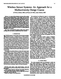
Multiple incoming and outgoing channels may be connected together enabling the specification of complex communication topologies. This facility introduces non-determinism into the send and receive operations. The semantics of send and receive can be explained in more detail by considering Fig.1 which depicts four connection topologies.
S1 cout
R1
1 0 0 cin 1 S1 cout
1 0 0 1
1 R1 0 0 cin 1
S1 cout
S1 cout
R1 1 0 0 cin 1
1 0 0 1 1 R1 0 0 cin 1
1 0 0 1 R2
1 0 0 cin 1
S2 cout
S2 cout
R2 1 0 0 cin 1 S3
b)
1 0 0 1
1 0 0 1 cout
a)
1 0 0 1
c)
1 0 0 1
d)
Fig. 1. Connection Topologies
Fig. 1 (a) depicts a one-to-one connection between a sender component labelled S1 and a receiver component labelled R1. The semantics of send and receive over a one-to-one connection are akin to sending data down a traditional pipe in that all values sent by S1 are received by R1 in the order they were sent. The topology in Fig 1 (b) represents a one-to-many connection pattern between a sender component S1 and two receiver components R1 and R2. Each value sent by S1 is non-deterministically received by either R1 or R2, but not by both. A usage scenario for the one-to-many connection pattern is that a sender component wishes to request a service from an arbitrary component in a server farm. From the perspective of the sender it is irrelevant which component receives its request. The connection topology shown in Fig. 1 (c) represents a many-toone connection pattern in which a number of output channels from potentially numerous components may be connected to an input channel associated with another component. For the depicted topology, R1 non-deterministically receives values from either S1 or S2 on a single incoming channel. In this pattern, the receiving component cannot determine the identity of the sending component or the output channel that was used to send the message and the arrival order of messages is determined by scheduling. The pattern is useful as a multiplexer in which R1 can multiplex data sent from S1 and S2 and could forward the data to a fourth component. The multiplexer pattern is used to allow multiple components to connect to a shared standard output channel. Each of the three basic patterns of connectivity depicted in Fig. 1 (a)-(c) may be hybridized to create further variations. An example variation combining the patterns from Fig. 1 (b) and Fig. 1 (c) is depicted in Fig. 1 (d).
4
Insense Channel Implementation
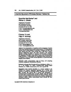
Insense channels are used for concurrency control and to provide inter-component communication via arbitrary connection topologies. Furthermore, the language is intended to permit components to be rewired and even replaced at runtime. The combination of component and channel abstractions reduces the complexity faced by the Insense programmer at the cost of increasing complexity in the channel implementation. Each Insense channel is represented by a half channel object in the implementation. Each half channel contains six fields: 1. a buffer for storing a single datum of the corresponding message type; 2. a field called ready which indicates if its owner is ready to send or receive data, 3. a field called nd received that is used to identify the receiving channel during a select operation, 4. a list of pointers, called connections, to the channels to which the channel is connected; and 5. two binary semaphores: one called mutex which serialises access to the channel and, 6. another called blocked upon which the components may block. When a channel is declared in the language a corresponding half channel is created in the implementation. Whenever a connection is made between an outgoing and an incoming channel in Insense, each half channel is locked in turn using the mutex. Next a pointer to the corresponding half channel is added to each of the connections lists and the mutex released. Disconnection is similar with the connections list being traversed and the bi-directional linkage between the half channels dissolved. The implementation of the send and receive operations are shown in Fig. 2 and were published in [10]. Numbers on the left hand side of the descriptions should be ignored - they are used for reasoning purposes in Section 5.2. The send and receive operations are almost symmetric. Both operations attempt to find a waiting component in the list of connections with the receiver looking for a waiting sender and vice-versa. If no such match is found the sender or receiver block on the blocked semaphore until they are re-awakened by the signal(match.blocked) statement in the corresponding receive or send operation respectively.
5
Verification of the Send and Receive Operations
In this section we describe the Promela implementation of the half channels and of the send and receive operations described in Section 4. We show how simple initial verification with SPIN using assert statements revealed a subtle error in the channel implementation. We then provide the corrected algorithms which have been developed with the help of model checking. A list of properties is given, specifying the semantics of the send and receive operations.
(a) The Send Algorithm
(b) The Receive Algorithm
Fig. 2. Original Send and Receive Algorithms
5.1
Send and Receive in Promela
Communication between Insense components over a channel is achieved by a send operation in one component and a corresponding receive operation in the other. We therefore model the operations in Promela using a Sender and a Receiver proctype (see Section 2.3). We can then verify the behaviour of the send/receive operations to/from given sets of components by initiating the appropriate Sender/Receiver processes within an init process (see Section 2.3). Both proctypes have an associated myChan parameter, which is a byte identifying a process’s half-channel. In addition the Sender proctype has a data parameter indicating the item of data to be sent. After initialisation we are not interested in the actual data sent, so a single value for each Sender process suffices. Half-channels Half-channels are implemented as C structs in the Insense implementation. They contain a buffer for storing an item of the channel type, semaphores and flags, and a list of other half-channels that this half-channel is connected to (see Section 4). In Promela, we implement half-channels using variations of the following typedef definition: typedef halfchan { // Binary semaphores bit mutex; // locks access to channel bit blocked; // indicates channel is blocked // Boolean Flags bit ready; //TRUE if ready to send/recv // Buffer byte buffer;
// List of connections to other half-channels bit connections[NUMHALFCHANS]; } Every sender and receiver is owner of exactly one half-channel. In our Promela specification all half channels are stored in a globally accessible array hctab. Note that we could have modelled the fields of each half channel as a set of channels (associated with a particular Sender or Receiver process). However we have used the halfchan construct to stay as true as possible to the original C implementation. Connections and Semaphores Each half-channel contains a list of other halfchannels to which it is connected. The connections list is an array of bits, where a value of 1 at index i indicates that the half-channel is connected to half-channel i in the hctab array. The Send and Receive algorithms use binary semaphores to synchronize. For example, if LOCK and UNLOCKED are constants denoting locked and unlocked status of a semaphore and me the half-channel parameter, then the wait operation (line (1) in Figure 2(a)) is represented by the following Promela code in the Sender proctype: atomic{ hctab[me].mutex!=LOCKED; // wait for mutex hctab[me].mutex=LOCKED //lock mutex } The lock can only be obtained if it is currently not in use (that is, it is currently set to UNLOCKED). If the lock is being used, the atomic sequence blocks until the lock can be obtained. The use of an atomic statement here ensures that race conditions do not occur. Data transfer In addition to the data item being transfered from sender to receiver, global flags are set to note the type of transfer. In the case of a single sender and receiver, there are two types of data transfer: either the sender pushes the data item to the receiver, or the receiver pulls the data item from the sender. Two bit flags, push and pull, used for verification purposes only, are set accordingly within appropriate atomic steps. Note that for our purposes it is sufficient for constant data values to be sent/received. In section 5.4 counters are used to ensure that duplicate data is not sent/received during a single run. 5.2
Error in the Original Version of the Send Algorithm
The send and receive algorithms were modelled in Promela as described above. Our initial model only involved one Sender and one Receiver process, where each process could only execute a single cycle (i.e. the processes terminated when the statement corresponding to return had been reached). The model was sufficient
to reveal a previously unobserved flaw in the send operation. This error was detected using an assert statement embedded in the Receiver proctype. After data has been pulled by the receiver, it should have the same value as that sent by the sender. Assuming that the sender always sends data with value 5, the assert statement is assert(hctab[me].buffer==5). A safety check showed that there was an assertion violation. Close examination of the output generated by a guided simulation provided the error execution sequence for our model. The corresponding sequence in the send and receive operations is illustrated in the algorithms given in Figs. 2(a) and 2(b), following the numbered statements from (1) to (10). Both processes obtain their own (half-channel’s) mutex lock, set their ready flag and release the lock. The receiver then checks that the sender is ready for data transfer (by checking its ready flag), then commences to pull data from the sender’s buffer. This is where the error occurs: the data item is copied although it has not been initialized by this stage. Inspection of the send algorithm shows that the sender’s buffer is not set until the penultimate line of code is reached. Possible fixes for this bug are to either set the sender’s buffer before setting the ready flag or to not set the ready flag until the buffer is initialized. To maximize parallelism, the former fix was implemented. The corrected algorithms are shown in Fig. 3. Note that in addition to the fix, a conns semaphore, used when dynamically connecting and disconnecting channels, is introduced to the half channel data structures and to both algorithms.
(a) The Send Algorithm
(b) The Receive Algorithm
Fig. 3. Corrected Send and Receive Algorithms
5.3
Extending the model for multiple processes
After adapting our Sender proctype to reflect the corrected version of the send operation, verification runs were performed to ensure that a model with single Sender and Receiver processes behaved as expected. They were then extended to run indefinitely, via additional goto statements and (start and return) labels. The current Promela implementation allows for multiple Sender and Receiver processes. Extra receivers require the global variable NUMHALFCHANS to be incremented, thereby adding an additional element to global data structures such as the half-channel table and the half-channel’s connection lists. Each receiver’s half-channel must be initialized in the init proctype and the each sender and receiver process instantiated. With multiple sender/receiver processes, variables used for verification must be adapted. In particular, rather than using a single bit to indicate a sender push or receiver pull, bit arrays of length NUMHALFCHANS are used. As with the global half-channels table, each element in these arrays is associated with a single sender or receiver process. Note that some of the properties described in Section 5.4 apply only when multiple sender or receiver processes are present. In particular, property 6, which is concerned with duplication of data, applies only to versions where a sender is connected to multiple receivers. 5.4
Properties
The following list contains the high-level requirements of the channel implementation provided by the Insense designers. This list was developed over a period of time during discussion between the designers and modellers. This helped to clarify the design specification. – Property 1 In a connected system, send and receive operations are free from deadlock – Property 2 Finite progress – in a connected system data always flows from senders to receivers – Property 3 For any connection between a sender and a receiver, either the sender can push or the receiver can pull, but not both – Property 4 The send operation does not return until data has been written to a receiver’s buffer (either by sender-push or receiver-pull) – Property 5 The receive operation does not return until data has been written into its buffer (either by sender-push or receiver-pull) – Property 6 Data passed to the send operation is written to exactly one receiver’s buffer. i.e. data is not duplicated during a single send operation – Property 7 The receiver’s buffer is only written to once during a single operation. i.e. data is never overwritten (lost) before the receive operation returns Before we can verify that the properties hold at every possible system state, they must first be expressed in LTL. Property 1 can be checked by performing a
no invalid endstates verification with SPIN, so no LTL property is required in this case. (This check would also reveal any assertion violations, like that exposing the bug in Section 5.2). In Table 1 we define propositions used in our LTL properties together with their meaning in Promela. The index i ranges from 1 to 3 and is used to access array elements associated with the ith sender or ith receiver process respectively. On the other hand, spid i and rpid i are variables storing the process identifiers of the ith sender/receiver process respectively and are used to remotely reference labels within a given sender/receiver process. Note that scount[i ] and rcount[i ] are array elements recording the number of push/pull operations executed. Variable scount[i ] is incremented when the ith sender is involved in a push or a pull, and decremented when the sender reaches its return label (similarly for rcount[i ]). Note that both senders and receivers can increment these variables, but the scount[i ]/rcount[i ] variables are only decremented by the corresponding sender/receiver. The ith elements of the push and pull arrays record whether a push or pull has occurred to or from the ith receiver. Table 1. Propositions used in LT L properties Proposition Definition Proposition Definition P ushi push[i] == T RU E P ulli pull[i] == T RU E SenderStarti Sender[spidi ]@start SenderReturni Sender[spidi ]@RET S1 ReceiverStarti Receiver[rpid i]@start ReceiverReturni Receiver[rpid i]@RET R1 Scountmax i scount[i] == 1 Rcountmax i rcount[i] == 1
We use the usual !, ||, && and → for negation, disjunction, conjunction and implication. In addition [], hi, and U denote the standard temporal operators “always”, “eventually” and “(strong) until” respectively. As shorthand we use W for “(weak) until”, where pW q denotes ([]p || (pU q)). In addition, for 1 ≤ j ≤ 3 we use the notation [PushOrPull ]j and [PushAndPull ]j to represent (P ush1 ||P ull1 || . . . ||P ushj ||P ullj ) and ((P ush1 &&P ull1 )|| . . . ||(P ushj &&P ullj )) respectively. Here R denotes the number of receivers. Properties are the same for any number of Senders greater than zero. – Property 2 • 1 ≤ R ≤ 3: []hi[PushOrPull ]R – Property 3 • 1 ≤ R ≤ 3: []![PushAndPull ]R – Property 4 • 1 ≤ R ≤ 3: [](SenderStart1 → ((!SenderReturn1 )W [PushOrPull ]R )) – Property 5 • 1 ≤ R ≤ 3: [](ReceiverStart1 → ((!ReceiverReturn1 )W (P ush1 ||P ull1 ))) – Property 6
• R = 1: Not applicable. • R > 1: [](SenderReturn1 → Scountmax1 ) – Property 7 • 1 ≤ R ≤ 3: [](ReceiverReturn1 → Rcountmax 1 ) Note that, since every process starts at the start label, properties 4 and 5 are not vacuously true. For properties 6 and 7 however, it is possible that in some paths the relevant Sender or Receiver never reaches the return label. This is acceptable - we are only interested here whether duplication is possible.
6
Experimental results
The experiments were conducted on a 2.4 GHz Intel Xenon processor with 3Gb of available memory, running Linux (2.4.21) and SPIN 5.1.7. 6.1
Verification of the corrected Send and Receive operations
To provide consistency, a template model was used from which a unique model was generated for each configuration and property being tested. This allowed us to control the state-space by only including variables that were relevant to the property being tested. Promela code for our template and some example configurations, together with claim files (one per property) and full verification output for all configurations and properties can be found in an appendix at http://www.dcs.gla.ac.uk/dias/appendices.htm. In Table 2 we give results for scenarios in which S sender processes are connected to R receiver processes, where R + S ≤ 4. Here Property is the property number as given in Section 5.4; time is the actual verification time (user + system) in seconds; depth is the maximum search depth; states is the total number of stored states; and memory is the memory used for state storage in megabytes. Compression was used throughout, and in all cases full verification was possible (with no errors). Note that there is no result for property 6 with a single receiver, as this property applies to multiple receivers only. 6.2
Verification of the Connect/Disconnect operations
The Insense designers worked closely with the model checking experts to develop previously unpublished algorithms for dynamic connection and disconnection of components. Using SPIN, deadlocks were shown to exist in previous versions of the algorithms. The final, verified algorithms are given in Fig. 4. We note that: – The connect and disconnect algorithms make use of: an additional Boolean is input field in the half channel data structures (that is set to true for incoming half channels) to prevent deadlocks from occurring by imposing a
Table 2. Results for sender and receiver verifications S:R 1:1 1:1 1:1 1:1 1:1 1:1 1:2 1:2 1:2 1:2 1:2 1:2 1:2 1:3 1:3 1:3 1:3 1:3 1:3 1:3 2:1 2:1 2:1 2:1 2:1 2:1 2:2 2:2 2:2 2:2 2:2 2:2 2:2 3:1 3:1 3:1 3:1 3:1 3:1
Property 1 2 3 4 5 7 1 2 3 4 5 6 7 1 2 3 4 5 6 7 1 2 3 4 5 7 1 2 3 4 5 6 7 1 2 3 4 5 7
Time 0.5 0.6 0.5 0.5 0.5 0.5 1.3 4.3 1.5 2.0 2.1 1.5 1.6 115.7 446.7 148.4 188.7 229.4 147.4 162.3 1.0 2.7 1.1 1.5 1.4 1.1 158.2 562.2 205.5 227.3 283.3 204.1 209.8 42.5 163.7 51.7 83.6 72.1 51.9
Depth 474 972 972 1014 971 969 1.9×10⁴ 4.1×10⁴ 4.1×10⁴ 4.2×10⁴ 4.1×10⁴ 4.0×10⁴ 4.3×10⁴ 1.0×10⁶ 2.2×10⁶ 2.2×10⁶ 2.1×10⁶ 2.2×10⁶ 2.1×10⁶ 2.4×10⁶ 1.5×10⁴ 3.2×10⁴ 3.2×10⁴ 3.3×10⁴ 3.2×10⁴ 3.2×10⁴ 2.3×10⁶ 5.0×10⁶ 5.0×10⁶ 5.1×10⁶ 5.0×10⁶ 5.0×10⁶ 5.1×10⁶ 5.9×10⁵ 1.2×10⁶ 1.2×10⁶ 1.4×10⁶ 1.2×10⁶ 1.2×10⁶
States 1488 2982 1518 2414 2425 1552 1.3×10⁵ 2.7×10⁵ 1.4×10⁵ 2.0×10⁵ 2.1×10⁵ 1.4×10⁵ 1.5×10⁵ 1.1×10⁷ 2.2×10⁷ 1.2×10⁷ 1.5×10⁷ 1.8×10⁷ 1.1×10⁷ 1.3×10⁷ 8.0×10⁴ 1.6×10⁵ 8.3×10⁴ 1.3×10⁵ 1.2×10⁵ 8.4×10⁴ 1.5×10⁷ 2.8×10⁷ 1.6×10⁷ 2.2×10⁷ 2.2×10⁷ 1.6×10⁷ 1.6×10⁷ 4.0×10⁶ 7.9×10⁶ 4.2×10⁶ 6.8×10⁶ 5.9×10⁶ 4.2×10⁶
Memory 0.3 0.4 0.3 0.3 0.3 0.3 4.0 9.7 5.3 7.3 7.9 5.3 5.7 351.6 832.0 439.3 576.8 678.0 437.1 486.2 2.5 5.9 3.3 5.1 4.7 3.3 460.1 1052.0 573.2 828.8 826.7 586.1 590.8 127.8 282.1 148.3 244.7 214.5 149.1
(a) The Connect Algorithm
(b) The Disconnect Algorithm
Fig. 4. Connect and Disconnect
–
– – –
7
common order on mutex locking for send, receive, connect, and disconnect operations; and a conn op mutex to prevent race conditions from occurring when executing multiple connect and disconnect operations concurrently. The use of a global lock here is not an ideal solution. However, its removal resulted in models with an intractable state space (exceeding a 32Gb available space limit) for more than 2 Sender or Receiver processes. Since our systems (and hence our Promela models) are inherently symmetric, progress could be achieved here with the application of symmetry reduction (see Section 7). In our Promela model, R × S Connect processes and R + S Disconnect processes are used to simulate connection and disconnection (1 Connect process per Sender-Receiver pair, and 1 Disconnect process per Sender or Receiver). The executions of these processes interleave with those of S Sender and R Receiver processes. As Property 2 of 5.4 refers to a connected system, it is not relevant in this context. All other relevant properties have been shown to hold for cases R + S ≤ 3. See Table 3. A (further) template model was used to generate models. This template and an example model is contained in the online appendix.
Conclusions and Further Work
This paper outlines an initial step towards verifying the correctness of WSN applications with a focus on concurrency. The general approach taken here is to
Table 3. Results for sender and receiver verifications, with additional Connect and Disconnect processes S:R 1:1 1:1 1:1 1:1 1:1 1:2 1:2 1:2 1:2 1:2 1:2 2:1 2:1 2:1 2:1 2:1
Property 1 3 4 5 7 1 3 4 5 6 7 1 3 4 5 7
Time 0.6 0.6 0.7 0.7 0.6 68.4 80.5 111.2 127.2 78.3 93.5 48.1 54.4 98.3 84.7 57.1
Depth 1.1×10³ 2.1×10³ 2.7×10³ 2.1×10³ 3.3×10³ 3.0×10⁵ 6.3×10⁵ 6.2×10⁵ 6.3×10⁵ 6.4×10⁵ 7.6×10⁵ 3.7×10⁵ 7.1×10⁵ 8.6×10⁵ 7.1×10⁵ 7.1×10⁵
States 1.5×10⁴ 1.5×10⁴ 2.4×10⁴ 2.4×10⁴ 1.6×10⁴ 5.1×10⁶ 5.3×10⁶ 7.6×10⁶ 8.2×10⁶ 5.3×10⁶ 6.2×10⁶ 3.7×10⁶ 3.8×10⁶ 6.4×10⁶ 5.7×10⁶ 3.8×10⁶
Memory 0.7 0.9 1.1 1.1 0.9 205.1 234.1 328.5 356.6 232.4 271.3 142.7 160.8 276.8 247.8 162.0
verify the implementation of the inter-component synchronisation mechanism of the Insense language using SPIN. Specifically, the Insense channel implementation and their associated send, receive, connect, and disconnect operations are first modelled using Promela constructs and SPIN is then used to verify a set of LTL properties under which the channel semantics are satisfied for a small number of senders and receivers. The SPIN model checker is used to reveal errors in a previously published version of the Insense channel implementation and to aid the development of revised algorithms that are correct with respect to their defined semantics. There are three avenues of further work in this area. First, the verification of the Insense language implementation is to be completed by modelling the nondeterministic select operation in Promela and using SPIN to check the relevant LTL properties. Second, we would like to show that the send and receive operations are safe for any number S of senders and any number R of receivers. This is an example of the parameterised model checking problem (PMCP) which is not, in general, decidable [2]. One approach that has proved successful for verifying some parameterised systems involves the construction of a network invariant (e.g. [16]). The network invariant I represents an arbitrary member of a family of processes. The problem here is especially hard, as we have two parameters, S and R. By fixing S to be equal to 1, however, we have applied an invariant-like approach, (from [18]) to at least show that a system with one sender process connected to any number (greater than zero) of receivers does not deadlock. (Details are not
included here, for space reasons). In future work we intend to extend this to the case where S > 1. Our systems are inherently symmetric, and could benefit from the use of symmetry reduction [19]. Existing symmetry reduction tools for SPIN are not currently applicable. SymmSpin [5] requires all processes to be permutable and for symmetry information to be provided by the user, and TopSpin [11] does not exploit symmetry between global variables. We plan to extend TopSpin to allow us to verify more complex systems and to remove the global lock from the Connect and Disconnect processes. Finally, an important aspect of further work is to extend our methodology from verifying the Insense language implementation to verifying programs. Our intention is to model WSN applications written in Insense using Promela constructs and to verify correctness of these programs using SPIN.
8
Acknowledgements
This work is supported by the EPSRC grant entitled DIAS-MC (Design, Implementation and Adaptation of Sensor Networks through Multi-dimensional Co-design) EP/C014782/1.
References 1. I. Akyildiz, W. Su, Y. Sankarasubramaniam, and E. Cyirici. Wireless sensor networks: A survey. Computer Networks, 38(4):393–422, 2002. 2. Krzysztof R. Apt and Dexter C. Kozen. Limits for automatic verification of finitestate concurrent systems. Information Processing Letters, 22:307–309, 1986. 3. D. Balasubramaniam, A. Dearle, and R. Morrison. A composition-based approach to the construction and dynamic reconfiguration of wireless sensor network applications. In Proc. 7th Int’l. Symp. on Software Composition (SC 2008), volume 4954 of Lecture Notes in Computer Science, pages 206–214. Springer, 2008. 4. P. Ballarini and A. Miller. Model checking medium access control for sensor networks. In Proc. of the 2nd Int’l. Symp. on leveraging applications of formal methods, pages 255–262. IEEE, 2006. 5. D. Bosnacki, D. Dams, and L. Holenderski. Symmetric Spin. International Journal on Software Tools for Technology Transfer, 4(1):65–80, 2002. ´ Bruneton, T. Coupaye, M. Leclercq, V. Qu´ema, and J.-B. Stefani. The fractal 6. E. component model and its support in Java. Software Practice and Experience, 36(11-12):1257–1284, 2006. 7. E. Clarke and E. Emerson. Synthesis of synchronization skeletons for branching time temporal logic. In Proc. of the 1st Workshop in Logic of Programs, volume 131 of Lecture Notes in Computer Science. Springer, 1981. 8. E. Clarke, E. Emerson, and A.P. Sistla. Automatic verification of finite-state concurrent systems using temporal logic specifications. ACM Transactions on Programming Languages and Systems, 8(2):244–263, 1986. 9. E. Clarke, O. Grumberg, and D. Peled. Model Checking. The MIT Press, Cambridge, MA, 1999.
10. A. Dearle, D. Balasubramaniam, J. Lewis, and R. Morrison. A component-based model and language for wireless sensor network applications. In Proc. of the 32nd Int’l Computer Software and Applications Conference (COMPSAC 2008), IEEE Computer Society, pages 1303–1308. IEEE, 2008. 11. A.F. Donaldson and A. Miller. A computational group theoretic symmetry reduction package for the SPIN model checker. In Proceedings of the 11th International Conference on Algebraic Methodology and Software Technology (AMAST’06), volume 4019 of Lecture Notes in Computer Science, pages 374–380, Kuressaare, Estonia, July 2006. Springer-Verlag. 12. A. Dunkels, B. Gr¨ onvall, and T. Voigt. Contiki – a lightweight and flexible operating system for tiny networked sensors. In Proc. 1st Workshop on Embedded Networked Sensors (EmNets-I). IEEE, 2004. 13. D. Gay, P. Levis, and D. Culler. Software design patterns for TinyOS. Transactions on Embedded Computing Systems, 6(4):22, 2007. 14. G. Holzmann. The SPIN model checker: primer and reference manual. Addison Wesley, Boston, U.S.A., 2003. 15. A. Khan and L. Jenkins. Undersea wireless sensor network for ocean pollution prevention. In Proc. 3rd Int’l Conference on Communication Systems Software and Middleware (COMSWARE’08), IEEE, pages 2–8, 2008. 16. R. P. Kurshan and K.L. McMillan. A structural induction theorem for processes. In Proceedings of the eighth Annual ACM Symposium on Principles of Distrubuted Computing, pages 239–247. ACM Press, 1989. 17. Marta Kwiatkowska, Gethin Norman, and Jeremy Sproston. Probabilistic model checking of the IEEE 802.11 wireless local area network protocol. In Proc. 2nd Joint Int’l Workshop on Process Algebra and Probabilistic Methods, Performance Modeling and Verification (PAPM-PROBMIV 2002), volume 2399 of Lecture Notes in Computer Science, pages 169–187. Springer, 2002. 18. A. Miller, M. Calder, and A.F. Donaldson. A template-based approach for the generation of abstractable and reducible models of featured networks. Computer Networks, 51(2):439–455, 2007. 19. A. Miller, A. Donaldson, and M. Calder. Symmetry in temporal logic model checking. Computing Surveys, 36(3), September 2006. 20. A. Skordylis, A. Guitton, and N. Trigoni. Correlation-based data dissemination in traffic monitoring sensor networks. In Proc. 2nd int’l conference on emerging networking experiments and Technoligies (CoNext’06), page 42, 2006. 21. L. Tobarra, D. Cazorla, F. Cuatero, G. Diaz, and E. Cambronero. Model checking wirelss sensor network security protocols: TinySec + LEAP. In Wireless Sensor and Actor Networks, volume 248 of IFIP International Federation for Information Processing, pages 95–106. Springer-Verlag, 2007. 22. S. Venkatraman, J. Long, K. Pister, and J. Carmena. Wireless inertial sensors for monitoring animal behaviour. In Proc. 29th Int’l Conference on Engineering in Medicine and Biology (EMBS’07), IEEE, pages 378–381, 2007. 23. G. Werner-Allen, K. Lorincz, M. Welsh, O. Marcillo, J. Johnson, M. Ruiz, and J. Lees. Deploying a wireless sensor network on an active volcano. IEEE Internet Computing, 10(2):18–25, 2006. 24. F. Xie, X. Song, H. Chung, and R. Nandi. Translation-based co-verification. In Proceedings of the 3rd International Conference on Formal Methods and Models for Codesign, pages 111–120, Verona, Italy, 2005. ACM-IEEE, IEEE Computer Society.