Traceability and Fine-Grained Constraints in Interactive Inconsistency Management Pieter Van Gorp1 , Frank Altheide2 , and Dirk Janssens1 1
{pieter.vangorp,dirk.janssens}@ua.ac.be Department of Mathematics and Computer Science University of Antwerp, Belgium 2
[email protected] Database and Information Systems University of Paderborn, Germany
Abstract. Software engineering is the multi-person activity of creating multiversion software. In the model-driven methodology, software artifacts are expressed in a variety of languages with a variety of tools. To manage the inconsistencies that can arise within and between software models, one needs a means to describe consistency constraints, detect violations of these and correct the models accordingly. This paper presents some lessons learned from building and using a platform for the development of interactive consistency maintenance software. Based on an established requirements engineering case study, the paper illustrates the need for developer interaction and the controlled tolerance of inconsistencies. This motivates the use of fine grained consistency constraints and a detailed traceability metamodel.
Introduction The specification of a software system, be it embedded control software or a large information system, is not monolithic. It consists of contributions from different disciplines (requirements engineering, security, enterprise architecture, ...) and models the system under development from different perspectives and at different levels of abstraction. The parts can overlap and contain redundant information, in any case they are interdependent. If the software system that results from this specification is to be free of errors then the parts of the specification need to be consistent. Consistency according to the IEEE “is the degree of uniformity, standardization, and freedom from contradiction among the documents or parts of a system or component” [1]. This paper uses this definition in the narrow sense by focussing on software models that need to be kept free of contradiction. Software models can be treated as graphs whose nodes represent model elements. Such nodes have attributes like name, author, visibility, etc. Edges represent links between the model elements. In an object oriented model, such edges represent associations, method calls, type declarations, etc. We will treat text documents as models as well: the nodes in this case are sections, chapters, etc. The set of relationships between the various models that are part of the specification can be perceived as an interconnection graph that joins the otherwise independent models.
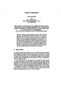
Fig. 1. Consistency relationships between objects
As Figure 1 illustrates, the relationships can differ in expressiveness: from very generic “is related to” relationships to precise relationships upon which formal constraints have been defined. Note that the IEEE defines traceability as the “the degree to which a relationship can be established between two or more products of the development process, especially products having a predecessor-successor or master-subordinate relationship to one another” [1]. The relationships in this definition are only established in the mind of a software developer. Therefore, this paper defines traceability links as the software artifacts that make these relations explicit in interconnection graphs called traceability models. The union of a traceability model and the models it connects is called an integrated model. This paper will illustrate the role of traceability models in tools for interactive consistency maintenance. Consistency can be achieved manually by reviews and inspections but also automatically by tools that evaluate constraints and restore consistency where constraints are not satisfied. Maintaining consistency over the course of the development is important but also work-intensive and time-consuming, therefore automation is desirable. The degree of automation that can be achieved however is highly dependent on the development environment, on existing processes and tools. There is a trade-off between costs and the degree of automation the developers obtain. In this paper we want to discuss the spectrum of consistency maintenance approaches and introduce two instances specifically: ToolNet [2] and CAViT [3] as representatives of manual and automatic consistency maintenance respectively. We will portray the work we carried out to combine these two approaches in the ICONS tool that supports interactive consistency maintenance. This paper is structured as follows: section 1 presents some models from a case study to motivate the need for consistency maintenance techniques. Section 2 introduces the reader to the functionality and implementation challenges of tools like ToolNet. Section 3 presents the other side of the tool spectrum by discussing the CAViT framework. Section 4 contains the core contribution of this paper. It illustrates the need for interaction, controlled inconsistencies and fine-grained consistency constraints in tools like ICONS. Obviously, this paper concludes by summarizing the lessons learned. 2
1
Case Study
To give a realistic idea of models that need to be kept consistent, this section presents some domain specific models of a sample application. The application is based on the Meeting Scheduler problem statement that was proposed by Van Lamsweerde et al. [4] as a benchmark for requirements elicitation and software specification techniques. The problem statement of the benchmark was published deliberately imprecise and incomplete [5]. The first part of the problem statement reads as follows: Meetings are typically arranged in the following way. A meeting initiator asks all potential meeting attendees for the following information based on their personal agenda: – a set of dates on which they cannot attend the meeting (hereafter referred as exclusion set); – a set of dates on which they would prefer the meeting to take place (hereafter referred as preference set). A meeting date is defined by a pair (calendar date, time period). The exclusion and preference sets are contained in some time interval prescribed by the meeting initiator (hereafter referred as date range). The initiator also asks active participants to provide any special equipment requirements on the meeting location (e.g., overhead-projector, workstation, network connection, telephones, etc.). He/she may also ask important participants to state preferences about the meeting location. The actual goal of the system is to propose an optimal meeting location and date and streamline the communication among the participants of a meeting. The proposed meeting date should belong to the stated date range and to none of the exclusion sets; furthermore it should ideally belong to as many preference sets as possible. A date conflict occurs when no such date can be found. The requirements specification distinguishes between different conflict types and describes ways of resolving them. Subsection 1.1 presents a conceptual model that formalizes the concepts, the associations and their multiplicities from the problem domain. Subsection 1.2 presents a robustness model for the “confirm meeting” use case scenario. The fragments in this paper should merely illustrate some realistic dependencies between models in different languages and should not be regarded as a complete or stable specification of a meeting scheduler. Instead, the sample models are meant to make the constraints in subsections 2.2, 3.2 and 4.2 more concrete. Since these constraints and their violations are designed to work on any application modeled by conceptual and robustness diagrams, the examples from the Meeting Scheduler should assist the reader in bridging the gap between the application model layer (M1) and the language model layer (M2) in the MOF metadata architecture [6]. 3
1.1
Conceptual Model
Figure 2 shows a conceptual model (CM) of a Meeting Scheduler application, specified in UML syntax [7]. At the conceptual level, analysts are free to use constructs such as association classes, views, and other language features. Such features may not be supported directly by the implementation language but they allow one to represent the problem domain in a way as close as possible to one’s perception of reality.
Fig. 2. Conceptual Model of a Meeting Scheduler application.
A complete conceptual model contains all relevant nouns and verbs from a problem domain as classes and operations. We could establish some traceability in this paragraph by describing in natural language how the words from Figure 2 relate to those from the requirements specification presented above. However, this would not be an adequate basis for automating the consistency maintenance between these two models. Moreover, developers may want some tool support for navigating from one model element to all its related elements in another model. 1.2
Robustness Model
The model-view-controller (MVC) pattern has been found beneficial for system evolvability [8]. Therefore, Rosenberg and Scott propose to move from analysis to design by creating robustness models [9]. User interface screens are represented by boundary objects (or interfaces), persistent classes from the conceptual model are represented by entities while application behavior is encapsulated by control objects (or services). A set of architectural rules (like “only services are allowed to access entities”) assists developers to create an evolvable design. Figure 3 shows a robustness model (RM [9]) of the application under study. Note that the entity Schedule corresponds to the class Schedule from Figure 2. The model describes the way a meeting can be confirmed by an initiator. After logging in, the initiator is directed to the main user interface screen of the application. There, he can select a particular meeting and click the “confirm meeting” button. This action triggers an update of the meeting status and a booking of the meeting location. 4
Fig. 3. Robustness Model of a Meeting Scheduler application.
Finally, the success of the use case is confirmed by sending a mail to all meeting attendees.
2
Manual Consistency Maintenance
This section illustrates how tools like ToolNet can assist developers in the manual construction of traceability links. We also discuss why one may want to restrict tool support to this low level of automation. 2.1
User Experience
A manual traceability tool like ToolNet allows one to create and navigate links between model elements. Figure 4 shows how a user may request all links related to the word “meeting” in the requirements document. A popup shows that this word is related to a model element with name “Meeting” in the application model. This model is stored in a UML tool and contains both the conceptual and the robustness model. Developers can also perform completeness checks on the set of traceability links. They may for example check whether every class in the conceptual model traces to a word in the requirements document. The underlying rationale of such a check is that artificial concepts in a conceptual model should be avoided whenever possible. 2.2
Implementation Challenges
ToolNet is a traceability tool for models residing in commercial off-the-shelf (COTS) development tools. Basili and Boehm [10] define COTS components as software with the following three characteristics: the buyer has no access to the source code, the vendor controls its development and it has a nontrivial user base. Unfortunately, the features of a component may not match the buyer’s requirements completely and it usually supports only a part of the overall development process. 5
Fig. 4. Screenshot from ToolNet operating on the requirements document of the Meeting Scheduler. This poses a number of integration challenges. First of all, extension and adaptation of the component is limited by the mechanisms provided by the vendor. Secondly, the components are unaware of each other. Thirdly, a vendor is not bound to adhere to standards but focuses on implementing a set of features to gain a competitive edge over his competitors. Lastly, the buyer has only limited influence on the development of the component. The visions of a specific buyer and the vendor may diverge, forcing this buyer to exchange one component for another. Still one needs a common language to reason about model elements and traceability links. ToolNet’s metamodel of such a language originally only supported directed and undirected binary links. The following OCL code formalizes the constraint described in the previous subsection on a metamodel for undirected n-ary traceability links: -- All classes in the CM should trace to a word in the requirements document let requirementsWordForEachCmClass(): Boolean= allClassesFromModel(cm)->forAll(cmClass| nodesOfElement(cmClass).link->select( oclIsKindOf(Class2Word) ).node->select(role="word")->size>0 )
Note that this constraint does not need the actual content of the text processor’s repository. This illustrates that some useful constraints can be enforced without knowing the precise metamodels of the integrated tools. ToolNet exploits this observation by implementing the minimalistic metamodel as the basis for a bus-like integration of COTS tools such as DOORS, Word, Matlab, StateFlow and MagicDraw. By exposing JMI interfaces for the traceability models, their repository can be integrated seamlessly with more expressive repositories such as the one containing the conceptual and the robustness model elements. The OCL constraint can thus be executed on the federated repository of the integrated model. In general, the ToolNet architecture needs to cope with the following challenges: 1. The models of the development tools do not comply to a common metamodel. ToolNet tackles this issue by exposing only a minimal interface between tools. 6
More specifically, tools expose interfaces for those artifacts that are essential in the development process. On top of those interfaces, the data structure for traceability links is defined. 2. The metamodels of the actual tools are often too generic for direct usage in the development process. Therefore, the implementation of the tool interfaces needs to take care of a gap in expressiveness. 3. The access to model repositories of the development tools is not standardized. This lack of a common abstract programming interface (API) makes accessing these repositories expensive in terms of amount of specialized code. In the context of the presented running example, the tool being integrated was MagicDraw UML, version 10. Since this tool conforms to a public MOF metamodel and exposes all UML metaclasses through JMI interfaces, we decided to expose the metamodel directly and completely to ICONS’s query and transformation engines. The potential lack of a common metamodel and the potential expressiveness gap can be tackled by the class of tools presented in the following section. In fact, ToolNet related work is being done in this direction [11]. However, a lot of COTS modeling tools are not model-driven nor JMI compliant. Moreover, even the development of metamodel mappings still requires a considerable development effort. Therefore, for some integrated tools one may want to restrict the set of metaclasses used in constraints and transformations to those from a minimalistic traceability and tool metamodel.
3
Automatic Consistency Maintenance
In model-driven engineering, stepwise refinement is supported by means of automatic model transformations to increase developer’s productivity and to enforce consistency. CAViT is a MOF compliant framework that extends the principles of design by contract for the implementation of model transformations. It allows architects to formalize the relationship between transformation rules and the consistency constraints they maintain in an object-oriented manner. Transformation rules are implemented as methods of a class that holds references to the input and output models. Consistency constraints are implemented as “transformation contracts”. Such a contract is defined by a pair of constraints: the postcondition describes the effect of a transformation method on the set of models provided that the precondition is satisfied. CAViT extends traditional design by contract by requiring that each postcondition corresponds to an invariant of the transformation class in which it is contained [3]. By implementing all desired consistency constraints as such invariants and postconditions, each instance of a transformation class can maintain the consistency of its contained models. More specifically, each time an invariant is violated for a transformation object, the CAViT engine can call the transformation method whose postcondition corresponds to that invariant and whose precondition holds at that point in time. 3.1
User Experience
Suppose that a developer has completed a conceptual model of the meeting scheduler by doing a noun/verb analysis on the requirements specification. Now he wishes to op7
timize the robustness of the application by building a design model that respects the model-view-controller principles. Therefore, he wants to construct a robustness model based on the main use cases. The developer wants to use his conceptual model as a basis for the persistent entities of this robustness model. However, he does not want to clutter the conceptual model itself with the upcoming design details. Therefore, he decides to copy all classes from the conceptual model to the robustness model and mark them as entities. Ideally, the construction of this initial robustness model from a conceptual model is supported by the development tool. With CAViT, software architects can build a library of transformations that developers can apply in a black-box manner. The following section illustrates how a conceptual model can be transformed automatically to a minimalistic robustness model. Application developers would launch this transformation by one click on a button. 3.2
Implementation Challenges
CAViT is built for integration with COTS modeling tools. As with ToolNet, a particular challenge is that the repositories of these tools cannot be changed. However, by following suitable guidelines in the design of a transformation model, a transformation repository can be wrapped seamlessly around its application model repositories. More specifically, associations between a transformation class and a metaclass from the application models should be specified unidirectionally. In summary, a software architect needs to provide three artifacts: (1) a MOF compliant definition of a transformation class, (2) a declarative consistency contract stating when a transformation method can establish what kind of consistency constraint and (3) a constructive body satisfying that contract. In the context of our running example, other work already discusses the former and the latter in detail [3,12]. The constraint presented in this section expresses that all classes from the conceptual model should correspond to entities in the robustness model. -- Sample consistency contract let CMconsistentRMcontract(): Boolean= conceptualmodelTracesToRobustnessmodel() and allClassesFromModel(cm)->forAll(cc: Classifier | allClassesFromModel(rm)->exists(rc: Classifier | this.traces->exists(t2 | t2.node->exists(cNode | cNode.content=cc) and t2.node->includes(rNode | rNode.content=rc) ) and cc.name=rc.name and rc.hasStereotype("entity") and cc.attributes()->forAll(ca| -- cc and rc have ’same’ attributes rc.attributes()->exists(ra| -- (note: attributes() defined on Class) ca.name=ra.name and ca.type.name=ra.type.name and (-- represent ’same’ type ca.typera.type or ( -- different class because should be copied -- take care of potentially used built-in types etc. not allClassesFromModel(cm)->includes(ra.type) ) ) ) ) ) )
8
The constraint is complex in that it asserts existential and qualitative properties about a variety of concepts (models, classes and attributes). This is acceptable for automatically establishing a global model property in one particular constraint violation scenario (or one particular precondition). However, it is too coarse grained to be associated with a set of small transformations that maintain parts of the constraint in an interactive manner. Therefore, it is decomposed in the following section.
4
Interactive Consistency Maintenance
The two previous sections might create the impression that all inconsistencies should be corrected automatically. However a number of authors have argued that inconsistencies should be tolerated under certain circumstances and that overly strict consistency maintenance can even be “foolish” [13]. Nuseibeh et.al. [14] even argue that each inconsistency must be treated differently. This is reflected in their proposed consistency maintenance process consisting of the following phases: (1) monitor for inconsistencies, (2) diagnose inconsistencies by means of locating, identifying and classifying, and finally (3) handle inconsistencies. The proposed actions are to ignore, tolerate or resolve an inconsistency. Tolerating an inconsistency can mean to defer, circumvent or ameliorate it. 4.1
User Experience
ICONS supports the consistency maintenance process by combining the facilities presented in the previous two sections. CAViT is used to monitor consistency constraints that were formalized in OCL. Diagnosis is supported both automatically and semiautomatically. More specifically, a model transformation can automatically assess a particular consistency violation and repair it without developer intervention. However, as an added value to CAViT, ICONS also enables transformations to present a set of violating model elements to a developer. Developers can then transform these elements manually or provide parameters to the CAViT backend. They can also specify that a particular inconsistency should be ignored by manipulating the ignoreConstraints property of a traceability link. This approach facilitates quality reviews in that inconsistencies are not just “tolerated” in an undisciplined manner: instead, they are “controlled” by a well-defined property of the traceability metamodel. A transformation has multiple constraints, each of which can be satisfied, violated or ignored. This state is visualized by means of a traffic-light analogy. Each constraint can use an arbitrary number of traceability links that may be used by other constraints as well. The state of individual traceability links can be computed on-demand. More specifically, developers can request to highlight all model elements that cause a particular inconsistency. Based on the ToolNet infrastructure, ICONS then allows developers to query for all links related to those elements. 4.2
Implementation Challenges
As pointed out before, the transformation metamodel needs to enable developers to ignore inconsistencies. Secondly, ICONS can only offer an interactive user experience 9
when constraints are checked in a fine-grained manner. Synchronization between finegrained constraints is realized by means of different classes of traceability links. More specifically, Figure 5 illustrates that one subclass of Link is provided for each set of related model element types.
CMconsistentRM (be.ac.ua.fots.transformations) applicationName : String
*
LinksOfCMconsistentRM
transformation
traceabilityLinks
*
Link (be.ac.ua.fots.metamodels.traceability) ignoreConstraints : Boolean = false
fix_eachClassTracesToAnEntity_violated_rmExists() : Boolean generateRMfromCM() : Boolean transformation * UMLmodelOfTransformation 1
applicationModel
Model
CM2RM
Class2Enttiy
Attribute2Attribute
Fig. 5. MOF instance representing the transformation model that defines the structure of the CMconsistentRM transformation and its traceability links. The navigability of the associations ensures that the Model class from the UML metamodel remains unaffected by the transformation. Link is also unaffected by the LinksOfCMconsistentRM association. Finally, the three subclasses of Link are defined in the transformation model such that they are stored in the proper repository.
The following OCL fragment illustrates how a part of the consistency of classes and entities is checked by two fine-grained constraints: -- Evaluate whether each class in the conceptual model traces to -- an entity in the robustness model let eachClassTracesToAnEntity(): Boolean= conceptualmodelTracesToRobustnessmodel() and -- ’rm’ not Undefined allClassesFromModel(cm)->forAll(cmc| allClassesFromModel(rm)->exists(rmc| this.traceabilityLinks->select(oclIsKindOf(Class2Entity))->exists(l| l.node->contains(cmc) and l.node->contains(rmc) ) ) ) -- Evaluate whether the classifiers (including entities) of all nodes related by -- a Class2Entity link have the same name let classEntity_name_match(): Boolean= traceabilityLinks->select(oclIsKindOf(Class2Entity))->forAll(l| -- for all relevant links: l.ignoreConstraints or -- user has marked that the name can be ignored, or l.node->forAll(n1,n2| -- for any couple of nodes, -- their content elements should have the same name n1.content.name=n2.content.name ) )
Figure 6 models how the the CAViT backend of ICONS contains callbacks for interacting with developers. The transformation iteratively selects those classes that are related to entities with a different name and for which the traceability link is not allowed to be ignored. For each pair of class and entity, the system prompts for user interaction. More specifically, the user should indicate whether the inconsistency should be solved 10
automatically, whether it should be ignored, or whether it should be solved manually. In the automatic case, the user should indicate whether or not the class name has precedence over the entity name. In the manual case, the system highlights the conflicting pair in the model editor.
lookupStereotypes {motmot.transprimitive=lookupStereotypes}
related to control flow Color Conventions related to interaction
Select Violating Classes and Entities {motmot.transprimitive=Select Violating Classes, motmot.constraint=classInCM.name!=entityInRM.name}
[not classEntity_name_match()]
[classEntity_name_match()] true
 fixType= chooseAlternative("How should ’"+classInCM.name+"’ be reconciled with ’"+entityInRM.name+"’?", new Object[]{"auto", "ignore", "manual"})


["auto".equals(fixType)]


["manual".equals(fixType)]


["ignore".equals(fixType)]  topdown= chooseAlternative(..., {"yes", "no"})


["yes".equals(topdown)]


Set link status to IGNORE {motmot.transprimitive=Set link status to IGNORE}


 setFocus("Reconcile names manually", new Object[]{classInCM, entityInRM})


["no".equals(topdown)]


Set name of entity to name of class {motmot.transprimitive=Set name of entity to name of class}


Set name of class to name of entity {motmot.transprimitive=Set name of class to name of entity}


Fig. 6. Story Diagram that models how a class should be reconciled with a related entity that has a different name. The behavior of most states is modeled as story patterns (primitive graph rewriting rules). Others contain a callback to one of two MOF compliant user interaction methods: setFocus or chooseAlternative. A detailed discussion thereof is left out due to space restrictions but can be found in an extended version of this paper [15].


5


Discussion


ICONS is a platform for the development of interactive consistency maintenance software. The platform consists of (1) code generators for interfacing repositories based on the Java Metadata Interface (JMI) standard, (2) a minimalistic JMI based library of methods for implementing interaction between model transformations and software developers and (3) a proof-of-concept plugin for the MagicDraw modeling tool. This paper presented parts of an ICONS application for maintaining the consistency between conceptual models, robustness models and requirements documents written in natural language. This case study has demonstrated that complex consistency constraints should be decomposed into smaller ones. This enables a tool to check fine-grained consistency constraints on fragments of models even when more coarse grained constraints have been violated in other model fragments. The coupling between the decomposed constraints consists of the navigation across traceability links of the same type. One group of constraints expresses when a particular type of traceability link should exist between 11


 a number of model elements while another group of constraints expresses what properties need to be satisfied by the related model elements. This interplay between consistency constraints was enabled by elaborating the traceability metamodels of ToolNet and CAViT. More specifically, an ICONS transformation model extends the generic CAViT traceability metamodel by subclassing the Link metaclass for each set of related model element types. Additionally, the case study illustrates how inconsistencies can be tolerated in a controlled manner. In fact, one boolean attribute of the Link metaclass sufficiently enables one to check whether a link is consistent or whether a developer allowed it to be inconsistent. Such attributes are exposed to developers by a dedicated user interface for working with traceability links. Within the ToolNet project, we have investigated two user interface approaches for interacting with these artifacts: (1) an application model centric approach based on tabular representations of the traceability data and (2) a graph based approach where traceability model elements are treated uniformly with application model elements. Based on ToolNet experience, the initial ICONS tool prototype (realized as a MagicDraw plugin) realizes an application centric, tabular representation of traceability links. This paper does not illustrate how ICONS could be applied for maintaining the consistency of relationships that are more complex than the one between classes and entities. In the end, the underlying OCL and controlled graph rewriting infrastructure is sufficiently expressive for reconciling any kind of conflicting yet formally related model elements. However, our simple case study already revealed some duplication and readability problems in the constraints and the rewriting rules. Therefore, the focus of our ongoing work lies on the development of more abstract (yet less widely applicable) constructs that solve reuse or readability problems that occur when performing well established case studies instead of intentially complex ones.


Conclusion Based on an established case study, this paper has illustrated that traceability links should be treated as first class software artifacts. The proposed traceability metamodel has a carefully designed inheritance hierarchy and enables one to tolerate inconsistencies in a controlled manner. A particular design of consistency constraints is motivated by illustrating how small and loosely coupled constraints allow one to manage inconsistencies in a fine-grained manner. Traceability links can also be used to support developers in the navigation across inconsistent models. Thus, they are an essential data structure in the communication between interactive model transformations and software developers.


Acknowledgements This work has been sponsored by the Belgian national fund for scientific research (FWO) under grant “Formal Support for the Transformation of Software Models”. Other sponsoring was provided by the European research training network “Syntactic and Semantic Integration of Visual Modeling Techniques (SegraVis)”. 12


 References 1. IEEE, editor. IEEE Standard Computer Dictionary: A Compilation of IEEE Standard Computer Glossaries. Institute of Electrical and Electronics Engineers, 1990. 2. F. Altheide, H. Dörr, and A. Schürr. Requirements to a Framework for sustainable Integration of System Development Tools. In H. Stoewer and L. Garnier, editors, Proc. of the 3rd European Systems Engineering Conference (EuSEC), pages 53–57, Toulouse, 2002. AFIS PC Chairs. 3. Pieter Van Gorp and Dirk Janssens. CAViT: a consistency maintenance framework based on visual model transformation and transformation contracts. In J. Cordy, R. Lämmel, and A. Winter, editors, Transformation Techniques in Software Engineering, number 05161 in Dagstuhl Seminar Proceedings. Internationales Begegnungs- und Forschungszentrum für Informatik (IBFI), Schloss Dagstuhl, Germany, 2005. 4. A. v. Lamsweerde and R. Darimont and P. Massonet. The Meeting Scheduler System Problem Statement. Technical report, Université Catholique de Louvain - Département d’Ingénierie Informatique, B-1348 Louvain-la-Neuve (Belgium), 1992. 5. M.S. Feather, S. Fickas, A. Finkelstein, and A. van Lamsweerde. Requirements and specification exemplars. Automated Software Engineering, 4(4):419–438, 1997. 6. Object Management Group. Meta Object Facility (MOF) specification. Object Management Group, 2002. Version 1.4. Available for download at url http://cgi.omg.org/cgibin/doc?formal/2002-04-03. 7. Object Management Group. Unified Modeling Language (UML), March 2003. version 1.5. document ID formal/03-03-01. 8. Takako Nakatani, Tetsuo Tamai, Atsushi Tomoeda, and Harumi Matsuda. Towards Constructing a Class Evolution Model. In Fourth Asia-Pacific Software Engineering and International Computer Science Conference, page 131, Clear Water Bay, Hong Kong, December 1997. IEEE Computer Society. 9. Doug Rosenberg and Kendall Scott. Use case driven object modeling with UML: a practical approach. Addison-Wesley Longman Publishing Co., Inc., Boston, MA, USA, 1999. 10. Victor R. Basili and Barry Boehm. Cots-based systems top 10 list. Computer, 34(5):91–93, 2001. 11. Johannes Jakob and Andy Schürr. View creation of meta models by using modified triple graph grammars. In Roberto Bruni and Daniel Varró, editors, Proc. ETAPS Workshop Graph Transformation and Visual Modeling Techniques (GT-VMT’2006), ENTCS. Elsevier, 2006. 12. Pieter Van Gorp, Hans Schippers, and Dirk Janssens. Copying Subgraphs within Model Repositories. In Roberto Bruni and Dániel Varró, editors, Fifth International Workshop on Graph Transformation and Visual Modeling Techniques, Electronic Notes in Theoretical Computer Science, pages 127–139, Vienna, Austria, 1 April 2006. Elsevier. 13. Anthony Finkelstein. A foolish consistency: Technical challenges in consistency management. In Proceedings of the 11th International Workshop on Database and Expert Systems Applications, 2000. 14. Bashar Nuseibeh, Steve Easterbrook, and Alessandra Russo. Leveraging inconsistency in software development. Computer, 33(4):pp. 24–29, 2000. 15. Frank Altheide, Pieter Van Gorp, and Dirk Janssens. ICONS: an interactive consistency maintenance platform. Technical report, Universiteit Antwerpen, Department of Mathematics and Computer Science, 2020 Antwerpen, Belgium, 2006.


13