IEEE Transactions on Consumer Electronics, Vol. 49, No. 4, NOVEMBER 2003
1178
Track-Following Control using a Disturbance Observer with Asymptotic Disturbance Rejection in High-Speed Optical Disk Drives Jung Rae Ryoo, Kyoung Bog Jin, Jung-Ho Moon, and Myung Jin Chung, Senior Member, IEEE Abstract — To obtain a good tracking performance in an optical disk drive servo system, it is essential to attenuate periodic disturbances caused by eccentric rotation of the disk. As an effective control scheme for enhancing disturbance attenuation performance, disturbance observers (DOBs) have been successfully applied to the track-following servo system of optical disk drives. In disk drive systems, the improvement of data transfer rate has been achieved mainly by the increase of disk rotational speed, which leads to the increase of the disturbance frequency. Conventional DOBs are no longer effective in disk drive systems with a high-speed rotation mechanism because the performance of conventional DOBs is severely degraded as the disk rotational frequency increases. This paper proposes a new DOB structure for effective rejection of the disturbance in optical disk drives with a very high rotation speed. Asymptotic disturbance rejection is achieved by adopting a band-pass filter in the DOB structure, which is tuned based on the information on the disturbance frequency. In addition, performance sensitivity of the proposed DOB to changes in disk rotational frequency is analyzed. The effectiveness of the proposed DOB is verified through simulations and experiments using a DVD-ROM drive. Index Terms — Asymptotic disturbance rejection, disturbance observer, optical disk drive system, trackfollowing control. I. INTRODUCTION Digital Versatile Disc (DVD) is a widely used optical storage medium for storing large amounts of digital audio/video data. As in the development of Compact Disc (CD) drives, efforts for improving data transfer rate have resulted in a steady increase of disk rotational speed in commercial DVD drives. The increase of disk rotational speed invokes several mechanical problems that should be dealt with by the disk drive servo system. One of the problems is the increase of disturbance frequency in the servo system. The goal of this paper is to design a track-following servo system for optical disk drives with a high-speed rotation mechanism. For data read-out in a DVD drive, the laser spot should be
positioned precisely on the center of a data track in the presence of external disturbances. Disturbances acting on the disk drive servo system are mainly caused by eccentric rotation of the disk and hence are inherently of a periodic nature having the same frequency component as the disk rotational frequency. Because the data track on the disk keeps moving inward and outward by the disturbances during the rotation of the disk, disturbance attenuation is one of the most crucial performance indices to be considered in the design of a disk drive track-following servo system [1], [2]. As an effective add-on controller for enhancing disturbance attenuation capability, disturbance observers (DOBs) for disk drive servo systems have been investigated in [3]-[6]. Despite the simple structure, DOBs are successful in improving trackfollowing control performance in disk drive servo systems. It is well known that the performance of a DOB depends on the cut-off frequency of a low-pass filter included in the DOB, i.e., the Q-filter. For a DOB to be effective, the bandwidth of the Q-filter needs to be sufficiently higher than the disturbance frequency. For this reason, many previous works have been devoted to increasing the cut-off frequency of the Q-filter without resulting in system instability [5], [7]. As the disk rotational speed increases with a view to obtaining better data throughput, so does the frequency of the periodic disturbance. The DOB for a disk drive servo system should be designed such that the cut-off frequency of the Qfilter is sufficiently higher than the disk rotational frequency and simultaneously a sufficient stability margin is guaranteed for the closed-loop system stability. Unfortunately, however, such a design might not be feasible in high-speed optical disk drives because the increase of the Q-filter cut-off frequency may cause an undesirable increase of the control bandwidth, which is established by a feedback controller. The bandwidth increase leads to a decrease of the phase margin or even an unstable system in the worst case. On this account, extending the Q-filter bandwidth is no longer applicable to optical disk drives with a very high rotation speed. To solve the problem, this paper presents a new DOB for the track-following servo system of a high-speed DVD-ROM drive. A constraint is eliminated from the DOB design by modifying the DOB structure and a filter included in the DOB is chosen such that asymptotic disturbance rejection can be obtained. To meet the well-known internal model principle, which states that for asymptotically tracking an oscillating reference input, the same oscillating mode should be included in the closed loop [8], [9], a band-pass filter is adopted for the
J. R. Ryoo and M. J. Chung are with the Department of Electrical Engineering and Computer Science, KAIST, Daejeon, Korea (e-mail:
[email protected],
[email protected]). K. B. Jin is with the Department of Control System Engineering, Korea University of Technology and Education, Cheonan, Korea (e-mail:
[email protected]). J.-H. Moon is with the Department of Electrical Engineering, Kangnung National University, Kangnung, Korea (e-mail:
[email protected]). Contributed Paper Manuscript received August 28, 2003 0098 3063/00 $10.00 © 2003 IEEE
J. R. Ryoo et al.: Track-Following Control using a Disturbance Observer with Asymptotic Disturbance Rejection in High-Speed Optical Disk Drives Neutral Position
Rotation Axis
x
Vertical Direction
Recorded Layer
Radial Direction
Disk
Spindle Motor
Objective Lens
Laser Spot
eT
C (s )
uc
uq
kf f
mf
df
dc Optical Element
PD
Fine Actuator
Coarse Actuator
Fig. 1. Schematic view of an optical disk drive track-following mechanism.
C (s )
u
P (s )
P(s )
x −
Q(s )
d
e
K PD
Q(s) K PD Pn ( s)
LD
mc
eT
M (s )
u
1179
x
d −
e
K PD Fig. 2. Block diagram of a general track-following servo system.
DOB. If the disk rotational speed is known exactly, the proposed DOB is capable of perfectly rejecting the external disturbance. Even when the disk rotational speed is slightly deviated from a nominal value, the proposed DOB shows a better performance of disturbance attenuation than conventional DOBs. The sensitivity of the proposed DOB with respect to changes in disturbance frequency is analyzed. In addition, some important issues to be considered for digitally implementing the track-following servo system are described. The performance of the proposed DOB is verified through several simulations and experiments with a DVD-ROM drive. II. SYSTEM DESCRIPTION AND LIMITATIONS OF THE DOB A. Track-following Servo System Track-following control in a disk drive is a radial position control for locating the laser spot on the center of a data track. Fig. 1 illustrates a schematic view of an optical disk drive track-following mechanism, which is a dual-stage actuator comprising a fine actuator and a coarse actuator. Because the role of the coarse actuator in track-following mode is simply to move the fine actuator slowly over the operation range, tracking performance is almost entirely dependent on the control of the fine actuator. In this paper, therefore, only the fine actuator is considered in the design of the track-following servo system. Shown in Fig. 2 is a general track-following servo system, where P(s ) is the fine actuator and C (s ) is a feedback compensator. d denotes a periodic disturbance signal of the disk rotational frequency caused by eccentric rotation of the disk. The position error between the track center and the laser spot position is amplified by the photo detector gain K PD and
Fig. 3. Structure of a track-following servo system using a conventional DOB.
then fed to C (s ) . As a result, the track-following servo system is formulated as an error feedback servo system as shown in the figure. The compensator C (s) is designed in such a way that a high loop gain is obtained at the disk rotational frequency for good disturbance attenuation and a sufficient phase margin is guaranteed for system stability. The fine actuator, which is a voice-coil-motor (VCM), determines the radial position of the laser spot x by moving the objective lens to which a spring and a damper are attached. Therefore, a second-order mass-spring-damper model is usually adopted to represent the fine actuator dynamics. The nominal model Pn (s ) of the fine actuator considered in the paper is expressed as 183.81 [V/m], (1) Pn ( s ) = 2 s + 209.21s + 159310 where the input and output are the terminal voltage of the fine actuator and the resultant objective lens position, respectively. Note that (1) is a nominal plant model that does not include the VCM coil inductance and high-frequency resonance modes, which are difficult to model. The control bandwidth, therefore, should be limited below 3 kHz in order not to excite the highfrequency resonance modes. B. Properties and Limitations of the DOB Fig. 3 depicts the structure of a track-following servo system for a disk drive, in which a conventional DOB is employed. The DOB creates an estimate of the disturbance and compensates for its effect using the estimate. Q(s) is chosen as a unity-gain low-pass filter since the advantage of the DOB is valid in the frequency region where Q( s) ≅ 1 . The feature originates from the high loop gain induced by the positive feedback block denoted by M (s) expressed as
M ( s ) = 1 (1 − Q( s)) ,
(2)
which indicates that as Q(s) approaches 1 at low frequencies, the gain of M (s) approaches infinity. Accordingly, it is desirable that Q(s) have as wider a bandwidth as possible. However, the allowable bandwidth of Q(s) is limited by requirements of control bandwidth and stability margin. Fig. 4 shows loop gains of the track-following servo system with and without the DOB, where a compensator given by
1180
IEEE Transactions on Consumer Electronics, Vol. 49, No. 4, NOVEMBER 2003
(a)
Fig. 4. Comparison of the open loop frequency responses with (solid) and without (dash) the DOB.
(b) Fig. 5. Simulation results: tracking error with the conventional DOB ((a) 4200 rpm, (b) 9000 rpm).
TABLE I. TRACKING SERVO SPECIFICATIONS REQUIRED AT TWO DIFFERENT ROTATIONAL SPEEDS
Q (s ) , which entails an undesirable increase of the control
Read-out Speed Disk rotation Disturbance freq. High freq. resonance Control bandwidth Required phase margin Required loop gain Roll-off
C ( s) = 0.64
8X
16 X
4597 RPM 76.6 Hz 20 kHz 3 kHz 60 deg 70 dB - 43 dB/dec
9194 RPM 153.2 Hz 20 kHz 3 kHz 60 deg 70 dB -54 dB/dec
( s + 2513)( s + 4398)( s + 5654) (s + 377)(s + 18850)(s + 31416)
and a third-order low-pass filter given by 3ω 2 s + ω c3 with ω c = 600π Q( s ) = c (s + ω c ) 3
bandwidth and decrease of stability margin secured by the feedback compensator C (s ) .
(3)
(4)
are used in constructing the loop gains. It is evident that the DOB-based servo system has much higher loop gain at low frequencies below 100 Hz without severely affecting the bandwidth and phase margin obtained with the compensator (3). According to the DVD specifications, the upper limit of the disk radial runout is peak-to-peak 100 µm and the allowed offtrack error limit is ±0.022 µm [10], which implies that a loop gain of at least 70 dB is required at the disk rotational frequency for an error-free read-out operation. In addition, a phase margin of 60 º is required as a stability margin. Table I summarizes the servo system specifications required at two different rotational speeds. It is readily verified from Fig. 4 and Table I that the servo system with the DOB using the lowpass filter Q (s ) in (4) meets the gain and phase requirements at the DVD 8X speed. The requirements, however, are not met even with the DOB at the DVD 16X speed. It may be possible to meet the gain requirement by increasing the bandwidth of
Fig. 5 presents simulation results performed at two different disk rotational frequencies, 4200 revolutions per minute (rpm) and 9000 rpm. The tracking error obtained at 4200 rpm remains below 0.022 µm designated by the dashed line, but the tracking error obtained at 9000 rpm is not acceptable. The results imply that the conventional DOB including a low-pass filter is no more effective in optical disk drives with a highspeed rotation mechanism, as expected from Fig. 4 and Table I. In the next section, we propose a new DOB for effective attenuation of the disturbances existing in high-speed optical disk drives. High-speed optical disk drives generally employ the Constant Angular Velocity (CAV) mode to eliminate the necessity for spindle velocity control according to the radial position of the laser spot. In such disk drives, therefore, the frequency of the periodic disturbance is known and measurable. The information of the known disturbance frequency will be advantageously used for achieving asymptotic disturbance rejection.
III. A NEW DOB FOR ASYMPTOTIC DISTURBANCE REJECTION A. Modified DOB Structure First, we present a modified DOB structure, which is a slightly modified version of the aforementioned conventional DOB structure. The low-pass filter Q(s ) included in the DOB should satisfy the following two requirements: • Properness of the inverse plant model block: the order of Q(s ) should be determined such that the transfer function
Q( s ) Pn−1 ( s ) is proper. • Stability preservation: the bandwidth of Q(s ) should be
J. R. Ryoo et al.: Track-Following Control using a Disturbance Observer with Asymptotic Disturbance Rejection in High-Speed Optical Disk Drives
eT
C (s )
uc
u uq
P (s )
x −
Q(s )
M (s )
d
1181
e
K PD
F (s) K PD Pn ( s )
Fig. 6. Structure of the track-following servo system using the modified DOB.
limited to preserve the overall system stability. The first requirement puts a restriction on the order of the filter Q(s ) . To get rid of the restriction from Q-filter design, we introduce another filter F (s ) dedicated to meeting the first requirement. The resultant modified DOB structure is shown in Fig. 6, where Q(s ) is also relocated. Because F (s ) is not a decisive factor in determining control performance, we can use a general low-pass filter with an appropriate bandwidth and order. It should be noted that the proposed DOB structure does not impose an additional computational burden because F (s )
Fig. 7. Frequency responses of the band-pass filter different values of
ς
Q(s ) with three
.
simply takes the place of Q(s ) in the inverse plant model block. The modified DOB structure provides more freedom for the Q-filter design with no additional expenses. B. Band-Pass Type DOB To achieve an asymptotic tracking property, we introduce a second-order band-pass filter given as 2ςω 0 s (5) Q( s ) = 2 s + 2ςω 0 s + ω 02
where ς is the damping ratio and ω 0 is the center frequency of the band-pass filter, which should be set to the disturbance frequency, i.e., the disk rotational frequency. With the above band-pass filter Q(s ) , the transfer function M (s ) is described as
Fig. 8. Open loop frequency responses with the modified DOB with three different values of ς .
(6)
gain sensitivity to changes in the disk rotational frequency in that ς determines the sharpness of the frequency response of
accordingly a sharp peak appears at ω 0 in the magnitude
Q(s ) around ω 0 . It is known that as ς increases, the magnitude response of
M (s) =
s 2 + 2ςω 0 s + ω 02 1 = , 1 − Q(s) s 2 + ω 02
response of the loop gain of the servo system shown in Fig. 6. It is obvious that due to M (s ) , the same oscillating mode as the external disturbance is included in the servo system. This fact means that the servo system is capable of asymptotic disturbance rejection, as the internal model principle states. The center frequency ω 0 of the band-pass filter Q(s ) is set to the disk rotational frequency, which is assumed to be exactly known. The actual rotational frequency, however, might differ slightly from the assumed frequency because of incomplete spindle control. For this reason, it is desirable that the loop gain of the DOB-based servo system be insensitive to changes in the disk rotational frequency. The other parameter ς of the band-pass filter Q(s) can be used to tune the loop
Q(s ) becomes wider around ω 0 . Hence, a large value of ς is preferable so as to obtain a loop gain that does not vary abruptly around ω 0 . Figs. 7 and 8 show frequency responses of Q(s ) with three different values of ς and the resultant frequency responses of the loop gain, respectively. In constructing the plots, ω 0 is set to 300π rad/sec corresponding to a disk rotation speed of 9000 rpm, and the added filter F (s ) is chosen as a second-order lowpass filter described as F ( s ) = 1 ( s 1400π + 1) 2 . As shown, a larger value of ς yields a wider magnitude response around ω 0 , which is accompanied with a smaller phase margin. In this respect, ς should be chosen carefully so as to obtain a good balance
1182
IEEE Transactions on Consumer Electronics, Vol. 49, No. 4, NOVEMBER 2003
Freq. Error -10% -1% Loop gain 0% (dB) 1% 10% Phase margin (deg)
TABLLE II. LOOP GAIN SENSITIVITY DOB with BPF ( ς ) Conv. W/O DOB DOB 0.25 1.0 4.0 47.0 44.3 44.0 43.7 41.4 70.6
53.5 49.6 49.2 48.8 45.5 67.3
55.1 72.2
66.5 84.2
78.5 96.3
71.7 50.3 68.7
83.7 61.8 63.0
95.8 73.8 44.8
∞
∞
∞
between loop gain sensitivity versus phase margin. Table II lists the loop gains of the servo systems without a DOB, with the conventional DOB, and with the modified DOB calculated around the assumed disk rotational frequency, 150 Hz, where the frequency error indicates the percentage of the disk rotational frequency deviation. Although the servo system with the proposed DOB shows larger gain variations around the disk rotational frequency regardless of the value of ς than
(a)
(b) Fig. 9. Simulation results: (a) external disturbance, (b) tracking error with the proposed DOB.
the servo system without a DOB or with the conventional DOB, it gives a much higher loop gain at each of the deviated rotational frequencies nevertheless. It is readily seen that as ς increases, the gain sensitivity decreases but the resulting phase margin also decreases, which indicates that ς can be used as a tuning parameter that provides a tradeoff between gain sensitivity and stability margin. The rotational speed of the spindle motor is controlled within an error limit of 1% in the CAV mode, therefore it is expected from Table II that an improved track-following performance is achievable without a significant decrease of the stability margin even when the disk rotational frequency is not exact. C. Simulation Studies We performed two simulations to examine the validity of the proposed DOB. In the simulations, it is assumed that a disk with an excessive radial runout of peak-to-peak 200 µm rotates at 9000 rpm, as shown in Fig. 9(a). The amount of the runout is two times as much as the runout limit according to the DVD specifications. The center frequency ω 0 of the band-pass filter
Q(s ) included in the proposed DOB was tuned to the disk rotational frequency, 300π rad/sec, to reject the disturbance caused by the disk runout. As shown in Fig. 9(b), the disturbance is completely rejected by the DOB so that the frequency component of 150 Hz does not appear in the tracking error. In the second simulation, it is assumed that the disk rotational frequency is deviated by ±1% from the assumed one, 150 Hz, due to incomplete spindle control. Fig. 10 shows the obtained tracking errors. In this case, the center frequency ω 0 of the band-pass filter Q(s ) does not match the disturbance frequency, therefore perfect disturbance rejection is not achievable. Nevertheless, the disturbance is sufficiently attenuated and the resulting tracking performance is still satisfactory in that the tracking errors remain within the
(a)
(b) Fig. 10. Simulation results: tracking error when the rotational frequency is deviated by (a) –1% and (b) +1%.
allowed limit of 0.022 µm.
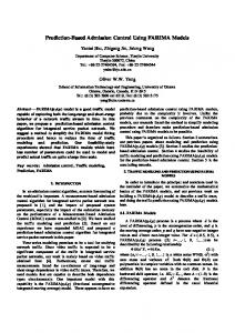
IV. EXPERIMENTS A. Experimental Environment The track-following servo including the proposed DOB was digitally implemented on a 32-bit floating-point digital signal processor (DSP), as illustrated in Fig. 11. We adopted the floating-point DSP just for convenience but it is not much more difficult to realize the track-following servo on a fixedpoint DSP. The program for the DOB-based track-following servo was executed at a sampling rate of 200 kHz, which is an extremely high sampling rate for control applications but common in commercial DVD-ROM drives. The powerful computing capabilities of the DSP make it possible to implement the digital servo algorithm having such a high sampling rate. The disk rotational speed is controlled in the CAV mode using Hall sensors attached to the spindle motor.
J. R. Ryoo et al.: Track-Following Control using a Disturbance Observer with Asymptotic Disturbance Rejection in High-Speed Optical Disk Drives
TABLE III. GAIN AND PHASE VARIATIONS DUE TO TIME DELAY FACTORS AND THE ZERO-ORDER HOLD
Actuator driver
Focus
PD signal
Freq. (kHz)
Fine Coarse Spindle
DAC
LPF DVD-ROM Drive Hall signal
DSP
1183
Pure Time Delay Zero-order Holder
Phase (deg) Mag. (dB) Phase (deg)
3 kHz
5 kHz
10 kHz
-3.2 -0.003 -2.7
-5.4 -0.01 -4.5
-10.8 -0.04 -9.0
Amp RF Amp
ADC
Focus error Tracking error
DSP based digital control system Fig. 11. Schematic view of the DSP-based digital servo system. (a)
ADC
DSP
DAC
T ADC : 0.5 µsec
TDSP : 1.5 µsec
TDAC : 1.0 µsec
Error Signal
G zoh (s )
To Actuator DVD-ROM Drive
Fig. 12. Time delay factors existing in the digital servo system.
B. Implementation Issues A digital equivalent of the DOB-based track-following servo, which was originally designed in the analog domain, is obtained by the bilinear transformation [11]. And, the digital controller was implemented as cascaded Infinite Impulse Response (IIR) filters in the DSP firmware. Because the sampling frequency is sufficiently higher than the control bandwidth of 3 kHz, the characteristics of the original analog controller are expected to be preserved fairly well by its digital equivalent. Additional time delays, however, are inevitably introduced to the digital control loop, which results in a decrease of the phase margin [12]. It is required, therefore, to analyze the undesirable effects of the time delays inherent in digital control systems. Fig. 12 illustrates time delay factors existing in the digital track-following servo system, where TADC , TDSP , and TDAC denote the analog-to-digital (AD) conversion time, the DSP computation time, and the digital-to-analog (DA) settling time, respectively. The sum of these three time delay factors amounts to about 3.0 µsec in our experimental setup. Another source of time delay is the zero-order hold the transfer function of which is expressed as 1 − e − sTs G zoh ( s ) = (7) sTs
(b) Fig. 13. Experimental results: tracking error at 3000 rpm (a) with the low-pass type DOB and (b) with the band-pass type DOB.
where Ts is the sampling period. The phase decrease induced by a time delay is dependent on the frequency at which the phase decrease is calculated. Table III lists magnitude and phase variations caused by the sum of the three time delay factors and the zero-order hold, the values being calculated at three exemplary frequencies, 3 kHz, 5 kHz, and 10 kHz. As the control bandwidth of the track-following servo is about 3 kHz, the phase decrease calculated at 3 kHz can be interpreted as the phase margin decrease induced by the digital implementation. In other words, a phase margin decrease of about 6º takes place in the digitally implemented track-following servo system. Such a phase margin decrease is unavoidable and thus should be taken into account in the design of the analog compensator (3). C. Experimental Results Experiments were conducted using two different controllers, one having the conventional low-pass type DOB and the other having the proposed band-pass type DOB. The same feedback compensator (3) was used in both cases in order to compare the effects of the two DOBs. Also, experiments were conducted at three different spindle speeds, 3000 rpm, 6000 rpm, and 9000 rpm with each DOB. The damping ratio ς of
Q(s ) included in the proposed DOB was set to 1 and the center frequency ω 0 was adjusted to the spindle frequency at each speed. Fig. 13 shows tracking errors by both controllers obtained when the disk rotates at 3000 rpm, where tracking errors are
1184
IEEE Transactions on Consumer Electronics, Vol. 49, No. 4, NOVEMBER 2003
(a)
(a)
(b) Fig. 14. Experimental results: tracking error at 6000 rpm (a) with the low-pass type DOB and (b) with the band-pass type DOB.
(b) Fig. 16. Experimental results: tracking error at 9000 rpm (a) with the low-pass type DOB and (b) with the band-pass type DOB.
(a)
(a)
(b) Fig. 15. Experimental results: frequency spectrum of the tracking error at 6000 rpm (a) with the low-pass type DOB and (b) with the band-pass type DOB.
(b) Fig. 17. Experimental results: frequency spectrum of the tracking error at 9000 rpm (a) with the low-pass type DOB and (b) with the band-pass type DOB.
sufficiently small and remain within the allowable limit designated by the dashed line. No noticeable performance difference is seen because the spindle frequency is relatively low. Fig. 14 shows tracking errors by both controllers obtained when the disk rotates at 6000 rpm. In this case, the tracking error by the controller with the conventional DOB exceeds the allowable limit from time to time, whereas the tracking error by the controller with the proposed DOB is still acceptable. The reason for the performance difference is clearly seen from Fig. 15 showing the frequency spectrums of both the tracking error signals. The disturbance appearing at the spindle frequency, 100 Hz, is successfully attenuated by the controller with the proposed DOB. However, the controller with the conventional DOB fails to attenuate the disturbance. The effectiveness of the proposed DOB can be far more obviously seen from Fig. 16, which shows tracking errors by both
controllers obtained when the disk rotates at 9000 rpm. Whereas the controller with the conventional DOB shows far worse tracking performance, the controller with the proposed DOB shows little performance degradation, the reason for which can be reconfirmed by the frequency spectrums of the tracking error signals shown in Fig. 17. It is evident from the above results that the proposed bandpass type DOB is excellent in rejecting disturbances of a very high frequency, which cannot be dealt with by the conventional low-pass type DOB.
V. CONCLUDING REMARKS In this paper, we proposed a new DOB structure for trackfollowing control in optical disk drives with a high-speed rotation mechanism. We could achieve an asymptotic tracking property against an external disturbance of a very high
J. R. Ryoo et al.: Track-Following Control using a Disturbance Observer with Asymptotic Disturbance Rejection in High-Speed Optical Disk Drives
frequency by adopting a band-pass filter in the DOB. Even when the disturbance frequency is slightly deviated from an assumed value by incomplete spindle control, the disturbance attenuation performance achieved by the proposed DOB was satisfactory. We verified the effectiveness of the proposed DOB by various simulation and experiments using a DVDROM drive. While the proposed DOB has been described with respect to the DVD-ROM, it can be applied to other optical disk drives that operate in the CAV mode.
REFERENCES [1]
T. H. Akkermans and S. G. Stan, “Digital servo IC for optical disc drives,” Contr. Eng. Pract., vol. 9, no. 11, pp. 1245-1253, 2001. [2] S. Bittanti, F. Dell’Orto, A. D. Carlo, S. M. Savares, “Notch filtering and multirate control for radial tracking in high-speed DVD-players,” IEEE Tran. Consumer. Electron., vol. 48, no. 1, pp. 56-62, Feb. 2002. [3] K. Fujiyama, R. Katayama, T. Hamaguchi, and K. Kawakami, “Digital controller design for recordable optical disk player using disturbance observer,” in Proc. Adv. Mot. Contr., 2000, pp. 141-146. [4] M. T. White, M. Tomizuka, and C. Smith, “Improved track following in magnetic disk drives using a disturbance observer,” IEEE/ASME Trans. Mechatron., vol. 5, no. 1, pp. 3-11, March 2000. [5] J. R. Ryoo, T.-Y. Doh, and M. J. Chung, “Disturbance Observer Design for Track-following Control in Optical Disk Drive using Structured Singular Value,” in Proc. Int. Conf. Contr., Automat., Syst., 2002. [6] K.-S. Kim, S.-P. Hong, “Enhancing the tracking performance in optical storage systems using a disturbance compensator,” in Proc. Amer. Contr. Conf., 2002, pp. 1384-1388. [7] Y. Choi, K. Yang, W. K. Chung, H. R. Kim, and I. H. Suh, “On the Robustness and Performance of Disturbance Observers for SecondOrder Systems,” IEEE Tran. Automat. Contr., vol. 48, no. 2, pp. 315320, Feb. 2003. [8] J. W. Howze and S. P. Bhattacharyya, “Robust tracking, error feedback, and two-degree-of-freedom controllers,” IEEE Trans. Automat. Contr., vol. 42, no. 7, pp. 980-983, July 1997. [9] L. H. Keel, S. P. Bhattacharyya, and J. W. Howze, “Robust tracking and disturbance rejection with two DOF controllers and distributed internal models,” in Proc. Amer. Contr. Conf., 1997, pp. 3892-3896, 1997. [10] DVD Forum, “DVD specifications for read-only disc—Part 1. Physical specifications. Version 1.01,” 1997. [11] K. Ogata, Discrete-Time Control Systems, Englewood Cliffs, NJ:Prentice-Hall, 1995. [12] J.-H. Moon, M.-N. Lee, M. J. Chung, S. Y. Jung, and D. H. Shin, “Track-following control for optical disk drives using an iterative learning scheme,” IEEE Tran. Consumer Electron., vol. 42, no. 2, pp. 192-198, May. 1996.
1185
Jung Rae Ryoo received the B.S. and M.S. degrees in electrical engineering from Korea Advanced Institute of Science and Technology in 1996 and 1998, respectively. He is currently studying toward the Ph.D. degree in electrical engineering at Korea Advanced Institute of Science and Technology. His research interests include robust motion control, optical disk servo control, and DSP-based digital control system. Kyoung Bog Jin received the B.S. and M.S. degrees in electrical engineering from Han-yang University in 1985 and 1987, respectively and the Ph.D. degree in automation and design engineering at Korea Advanced Institute of Science and Technology in 1999. He is currently with Department of Control System Engineering at Korea University of Technology and Education, where he is currently an Assistant Professor. From 1987 to 1994, he worked for Samsung Electronics Co., Ltd. in the field of servo technology, and from 1999 to 2000, he worked for ODD R&D Group of Samsung Electronics Co., Ltd as a senior research engineer. His research interests include optical disk servo control, robust control, and iterative learning control. Jung-Ho Moon received the B.S. degree in control and instrumentation engineering from Seoul National University in 1991, the M.S. and Ph.D. degrees in electrical engineering from Korea Advanced Institute of Science and Technology in 1993 and 1998, respectively. In 2002, he joined the faculty of the Department of Electrical Engineering, Kangnung National University, Korea, where he is an Assistant Professor. From 1998 to 2000, he worked for Samsung Electronics Co., Ltd as a Senior Research Engineer, and from 2001 to 2002, he worked for Humax Co., Ltd as a Senior H/W Engineer. His research interests include iterative learning control, digital control, and disk drive servo systems. Myung Jin Chung received the B.S. degree in electrical engineering from Seoul National University in 1973, the M.S. degree in electrical and computer engineering in 1977 and the Ph.D. degree in computer, information, and control engineering in 1983 both from the University of Michigan. Since 1983, he has been with the Department of Electrical Engineering and Computer Science at Korea Advanced Institute of Science and Technology, where he is currently a Professor. In 1976, he worked for the Agency for Defense Development, Seoul, as a member of technical staff and from 1981 to 1983 he worked for the Center for Robotics and Integrated Manufacturing, the University of Michigan. His research interests include robust control, intelligent control, robot path planning and control, tele-robot control, and multi-sensor fusion.