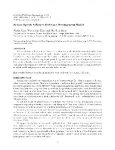
Tracking Requirements and Threats for Secure Software Development Brandon Malone
Ambareen Siraj
Department of Computer Science Tennessee Technological University Cookeville, TN 38505, USA
Department of Computer Science Tennessee Technological University Cookeville, TN 38505, USA
[email protected]
[email protected] A structured software development process offers many advantages over more ad hoc approaches. Primarily, a structured method can lead to consistent, replicable development results [2]. Modeling can assist a structured development process by allowing abstract representation of decisions made at different stages throughout the process, allowing the most educated decisions to be made at the right time [10].
ABSTRACT Many opportunities of use of systems also open doors for their misuse. Misuse of a system could manifest itself in a variety of forms. One common misuse of a system lies in security breaches. This research investigates tracing requirements and threats through a series of models to identify, maintain the visibility of, and ultimately help mitigate, security threats to a system. The proposed Tracking of REquirements And Threats (TREAT) approach is a model driven framework which blends together several known modeling techniques to conceptualize and design a secure software system. TREAT considers security requirements along with system requirements from the very inception of the software and traces them throughout the software lifecycle in between various software artifacts.
This paper proposes the Tracking of REquirements And Threats (TREAT) approach, a model driven framework which blends together several known modeling techniques to conceptualize and design a secure software system. Security requirements are considered along with system requirements from the very inception of the software and can be traced throughout the software lifecycle in between various software artifacts. Section 2 examines related works to TREAT. Section 3 presents TREAT in detail with brief background on the various modeling techniques it incorporates. Section 4 illustrates an example that brings the TREAT process to life. Finally, future work and conclusions close the paper.
Categories and Subject Descriptors D.2.10 [Design]: Methodologies
General Terms Design, Security, Verification.
Keywords 2. RELATED WORK
Requirements Tracking, Misuse Case, Security Engineering.
While risk analysis and security remain elusive goals to track down, many existing methods describe various development activities that can boost confidence in the security of a system. Some approaches consider the system conceptually, focusing only on hypothetical compromises in system architecture. An example is The Architectural Tradeoff Analysis Method (ATAM) that lends "a structured technique for understanding the tradeoffs inherent in the architectures of software intensive systems" [3]. Other methods direct their attention to actual implemented systems like Wang et al. who investigate a method that derives threat traces using UML sequence diagrams [9]. There are other security techniques that fall somewhere between the very abstract and very concrete system descriptions. Pauli and Xu propose an architectural design and analysis approach to designing secure information systems driven by threats [6, 7] using use and misuse cases and candidate architectures. The TREAT approach embraces risk analysis and security at all stages of development. Rather than tossing the existing methods out the window [3, 6, 7, 9], it attempts to match the most pertinent form of risk analysis to each development stage. E.g., while constructing and evaluating system architectures, TREAT employs ATAM to identify security compromises. Wang et al.‟s threat model security testing assists in testing the system source code. TREAT draws on Pauli and Xu‟s threat driven approach for tracking threats. By espousing a number of different security analysis methods, TREAT addresses security problems throughout the entire software life cycle.
1. INTRODUCTION Systems often suffer from security vulnerabilities because their development approaches incorporate security aspects in an ad hoc or “penetrate-and-patch” manner instead of building security in from the very beginning of the software life cycle [5]. Tracing desired system functionality into an actual implementation benefits other aspects of development, as well. Seeds of tracing sown early in the development planting season reap benefits when assessing change impact later in the project harvest.
Permission to make digital or hard copies of all or part of this work for personal or classroom use is granted without fee provided that copies are not made or distributed for profit or commercial advantage and that copies bear this notice and the full citation on the first page. To copy otherwise, or republish, to post on servers or to redistribute to lists, requires prior specific permission and/or a fee. ACM-SE ‘08, March 28–29, 2008, Auburn, AL, USA. Copyright 2008 ACM ISBN 978-1-60558-105-7/08/03…$5.00.
278
Also, tagged values label any connection which is threatened by or mitigates a misuse in that context. Hence, this step precisely ties together the use cases and the components, as well as tracks security threats from the misuse cases directly to specific system components and messages.
3.4 System Structure
TREAT begins by capturing desired system functionality with the help of use case and misuse cases. Use case diagrams help to address questions such as: What task shall the system facilitate? Who shall perform the task? While use cases model functionality the system should exhibit, misuse cases uncover opportunities for the abuse of system; that is, they describe actions that must not occur in order to preserve assurance in the functionality of the system. For a more detailed discussion of use and misuse cases, please refer to [4, 8].
Following logical behavior modeling, TREAT further refines the architectural sequence diagrams into robustness diagrams. Robustness diagrams help to answer questions such as: What sort of behavior do the elements exhibit? How do the elements work together to fulfill the system activities? [1] Different elements within the system supply different functionality to the overall application. Some handle interactions with users or outside systems; others persist data pertinent to system, and others manage complex business logic. In TREAT, all components interacting with an actor become boundary classes as they must handle the communication between the system and the outside entity. The rest of the components function as controller classes that manage the application flow, or represent externally implemented components which do not require classes. Tagged values adorn each of the components threatened by or mitigating a misuse. The messages themselves also serve as objects in the system. Entity classes represent the messages sent between the boundary and controller components. These entities maintain all parameters passed from the first component to the second. The entity classes also receive a tagged value for each threatening or mitigated misuse case. The tagged values maintain valuable tracking information that links each class to relevant security concerns.
3.2 Component Architecture
3.5 System Interfaces
Next, TREAT develops and evaluates potential component architectures. Component diagrams help to address questions such as: What elements are required to fulfill the tasks in the use cases? What elements are required to mitigate the threats in the misuse cases? The component diagram maintains an abstract view of the elements of the system [1]. The diagram distinguishes between each distinct logical component and the messages passed between them. In this manner, the component diagram reflects the interactions between business and technical infrastructure system components. In addition to enumerating the components, component diagram can also be used to illustrate the interfaces facilitating the communication between them [1]. TREAT uses a traceability chart, similar to that of Pauli and Xu, to track which components contribute in order to complete each of the use cases [6, 7].
Finally, TREAT generates system interfaces with class diagrams for the controller and boundary classes identified in the sequence and robustness diagrams. Class diagrams help to answer questions such as: What are the properties and behaviors of the classes? What are the static relationships between the classes? It describes the classes that compose the system [4]. Included with the classes come the properties and behaviors of each, as well as the static relationships between them. In TREAT, the system interface follows directly from the message passing in sequence diagrams. For every message originating from a boundary or controller class, the class contains a method named Send, where is the name of the entity class representing the message. The Send method has no parameters; its duties only include generating an instance of the entity class and invoking an appropriate Receive method. A Receive method lies in the interface for every message destined for the boundary or controller class. The Receive method, named Receive, where is the name of the entity class representing the message, handles the call from a Send method. The Receive method accepts a single argument: an instance of the entity class representing the message. Its diverse responsibilities can include updating any state variables of the class, invoking any Send methods as indicated by the sequence diagrams, etc. Currently TREAT does not address determining or updating state variables. That task remains in the hands of the developer.
Figure 1. The Tracking of Requirements And Threats approach.
3. THE TRACKING OF REQUIREMENTS AND THREATS APPROACH (TREAT) TREAT is proposed with the belief that a truly secure development process must consider security at all levels. Following is a description of the TREAT model (figure 1).
3.1 Requirements and Threats
3.3 Logical Behavior After identifying the components and their interrelationships, TREAT elaborates on the logical architectural behavior between the components with the help of sequence diagrams. Sequence diagrams address questions such as: What messages flow between the components? Which messages occur in which order to complete each use case? For each use case, one (or more) sequence diagram(s) depicts the temporal and logical relationships between the messages [4]. In TREAT‟s logical behavior modeling, in order to highlight security details, any component which is threatened by or helps to mitigate a given misuse case in the context of the use case in question receives an appropriate tag.
3.6 Evaluation and Comparison Throughout the development process, TREAT evaluates the security of the system to ensure its ability to quash any threats to
279
architecture employs the heuristic of adding a component for each use case. Also, the system relegates the „Encrypt Data‟ task to Secure Socket Layer (SSL); hence, it appears as a component in the system. At this point, the ATAM approach could identify tradeoff points highlighting security compromises in the architecture [3]. Figure 3 portrays the component architecture. Table 1 charts the components necessary to implement use cases.
its expected secure operation. Misuse cases initially recognize the threats to the system description. Later, use of ATAM assists evaluation of component architectures [3]. A variety of heuristics identify security risks and inconsistencies in later models. Finally, use of Wang et al.‟s threat model security testing verifies the security of the final source [9]. In TREAT misuse cases materialize hazards to the system and justify security-related entities in more refined system descriptions. Employing ATAM on the proposed system architecture(s), sensitivity points are associated with components based on expert opinions. With that knowledge, the tradeoff points highlight components with more than one sensitivity point.
4.3 Logical Behavior With a subset of the use cases and components defined, development begins to refine them into a series of logical steps. Following TREAT, each use case receives elaboration in a sequence diagram enumerating the message passing between components necessary to realize the use case. Additionally, the diagram includes tagged values mapping the components to relevant security concerns. Application of the heuristics described in Section 3.6 can ensure consistent security descriptions between the use case diagrams and the sequence diagrams.
As the design process unfolds, TREAT continues to keep tabs on security concerns. Several heuristics help identify inconsistencies between the logical system behavior and the previous development artifacts. First, within a given sequence diagram, a simple check can ensure consideration of associated mitigation for all threats. Unmitigated threats raise a flag as potential security vulnerabilities. Additionally, after specifying a sequence diagram for a given use case, a comparison between the misuses documented in the use case diagram and the sequence diagram can reveal any potential threats not carried over from the more abstract diagram. Also of benefit, threats discovered in the sequence diagrams but absent from use cases indicate a necessary revision to the use case diagram, and hence call for a second look at requirements and threat analysis.
Figure 4 elaborates the sequence diagrams for the „Fill Shopping Cart‟ use case. While the figures somewhat veil the fact, other sequence diagrams may refine certain portions of these high level uses of the system. E.g., a more specific sequence diagram may describe the „Show Screen‟ interaction between the system and the user in the „Fill Shopping Cart‟ diagram in more detail.
4.4 System Structure From the sequence diagrams flow the robustness diagrams. According to TREAT, each component interacting with an actor translates into a boundary class, and all other components correlate to controller classes or externally implemented components. Since SSL is externally implemented in the system, it does not require any classes. Additionally, each message between system components necessitates an entity class. Figure 5 contains the robustness diagram for „Make Secure Purchase‟.
TREAT does not drop its guard even after the implementation of the source code. Dynamic source code analysis techniques evaluate the runtime execution of the source. The Send and Receive methods derived in the system interfaces closely resemble the source code expectations for the threat model security testing of Wang et al [9]. Simple additions to the beginning and ending of the Send and Receive methods, in tandem with automating random user actions, facilitate the generation of execution traces. After an investment of time in specifying the threat traces, comparison between the two reveals threats manifest in testing.
4.5 System Interfaces Using the sequence diagrams and robustness diagrams, TREAT derives the software interfaces for the boundary and controller classes. Using the class distinctions discovered in the robustness diagrams and the messages defined in the sequence diagrams, Send and Receive methods accrue to the boundary and controller classes. Based on the Send and Receive methods, simple source code additions can allow security testing using the automated threat trace method of Wang et al [9]. Figure 6 presents the interfaces derived from the sequence and robustness diagrams.
4. AN ILLUSTRATED EXAMPLE In order to bring the Tracking of Requirements and Threats approach to life, a simple example stepping through each of the five steps is considered. The diagrams model a simple online store that allows customers to fill a shopping cart, procures their credit card information, and then sends the relevant information to a credit card processing service. Of course, the system should ensure the integrity of the order and the secrecy of the customers.
5. CONCLUSIONS
4.1 Requirements and Threats
TREAT embraces the belief that a secure process leads to a secure system. It contributes to secure software engineering by proposing a framework that allows consideration of and tracking of security at all stages of system development. By blending a combination of known approaches with existing and novel application, it helps to ensure a secure system implementation.
Because the store wishes to allow customers to make purchases, this becomes a use case. The first stage of this action entails allowing the user to fill a shopping cart. Care must be paid to prevent a hacker from altering the contents of the cart. Figure 2 models a more complete description of the interactions between users, the system, and attackers. Textual descriptions have been omitted due to spatial constraints.
TREAT advocates utilizing misuse cases and ATAM to identify threats in the initial system description and architecture. It proposes extension to existing modeling techniques such as sequence, robustness, and class diagrams to trace identified threats into source code. It also proposes a series of heuristics to identify inconsistencies in security specification and their
4.2 Component Architecture Next, an architecture describes the components necessary to fulfill the use case requirements. No hard and fast rules govern the generation of the architecture from the use cases; however, this
280
descriptions in between the modeled diagrams. Wang et al.‟s threat traces are utilized to test the final source code. TREAT is a work in progress. Future work on TREAT would be to investigate aspects such as consideration of message types in analysis and derivation of security metrics to aid analysis. Additional endeavors could aim to develop CASE tools facilitating the process.
6. REFERENCES [1] Ambler, S. W. “Agile Models Distilled: Potential Artifacts for Agile [2] [3] [4] [5] [6] [7] [8] [9] [10]
Modeling”, Agile Modeling, http://www.agilemodeling.com/artifacts. Accessed 4/15/2007. Hefner, R. 1997. Lessons learned with the systems security engineering capability maturity model. In Proceedings of the 19th international Conference on Software Engineering. ICSE '97. ACM, New York, NY. Kazman, R., Klein, M., Barbacci, M., Longstaff, T., Lipson, H., and Carriere, J. The Architecture Tradeoff Analysis Method. Int‟l Conf. Engineering Complex Computer Systems (ICECCS98). Aug. 98. Lethbridge, T.C. and Laganière, R. Object-Oriented Software Engineering: Practical Software Development using UML and Java, McGraw-Hill, 2005, p. 138. McGraw, G. “Testing for Security During Development: Why we should scrap penetrate-and-patch”, IEEE Aerospace and Electronic Systems, 13(4), pages 13 – 15, April 1998. Pauli, J. and Xu, D. Misuse Case-based Analysis of Secure Software Architecture, In Proc. of ITCC'05, April 2005. Pauli, J. and Xu, D. Threat-Driven Architectural Design of Secure Information Systems. In Proc. of ICEIS‟05, Miami, May 2005. Sindre, G. and Opdahl, A. "Capturing Security Requirements through Misuse Cases", Norsk Informatikkonferanse 2001. 2001. Wang, L., Wong, E., and Xu, D. A Threat Model Driven Approach for Security Testing. Int‟l Conf. Software Engineering Workshops. 2007. Zinnikus, I., Elvesæter, B., Fischer, K., Vayssiere, J., and Benguria, G. 2006. A Model Driven Approach to Agent-Based Service-Oriented Architectures. (Erfurt, Germany, September 2006).
Figure 2. Requirements and Threats with Use Case Diagram.
Figure 3. Component Architecture with Component Diagram.
Figure 4. Logical Behavior with Sequence Diagram for Fill Shopping Cart use case.
Figure 5. System Structure with Robustness Diagram.
Figure 6. System Interfaces with class diagram. 281