TrafRoute: A Different Approach to Routing in Vehicular Networks Raphael Frank∗ , Eugenio Giordano†‡ , Pasquale Cataldi§ and Mario Gerla† ∗ Department
of Computer Science - University of Luxembourg, 1359, Luxembourg e-mail:{
[email protected]} † Computer Science Department - University of California, Los Angeles, CA 90095, US e-mail: {giordano|gerla}@cs.ucla.edu § Mobile Communications Department - EURECOM, Sophia-Antipolis, 06560, France e-mail:{
[email protected]} ‡ DEIS, WiLab - Universit`a di Bologna, Bologna, 40136, Italia Abstract—In the near future vehicular networks based on wireless technology will be part of our lives. Efficient and robust routing algorithms will play a key role in the success of such technology. In this paper we present TrafRoute, an efficient and robust routing scheme for vehicular networks, suitable for both Vehicle-to-Vehicle and Vehicle-to-Infrastructure communications. TrafRoute introduces a novel approach to routing that involves landmark-based routes and forwarder self-election, exploiting the knowledge of the underlying road network. We demonstrate TrafRoute’s efficiency and robustness through simulation studies performed with accurate mobility and propagation models. Index Terms—Vehicular Networks, Routing, Efficient Forwarding, IEEE802.11, Simulation.
I. I NTRODUCTION Routing in vehicular networks is challenged by extremely large number of nodes, high mobility and very uneven node density (with aggregation at intersections). Traditional routing solutions investigate three main approaches: proactive, reactive and geographic routing. Proactive protocols require a distributed global knowledge of the network, which is maintained by periodic updates. In a Vehicular Ad hoc Network (VANET), high mobility forces frequent updates. The high update rate and the large number of nodes in a VANET severely impact proactive routing scalability and make it a poor choice for urban vehicle routing. Reactive protocols build routes on demand, thus scale better to number of nodes. However, these protocols are vulnerable to high mobility, as paths frequently break. Geographic routing outperforms proactive and reactive routing in most urban setting and is, in fact, by far the preferred scheme. It is stateless, and thus unlimitedly scalable to network size. It approximates well the minimum total distance path. It has however some drawbacks. For example, during its greedy progress, it can get stuck in local maxima. The popular perimeter routing escape from local maxima does not work well in urban grids, as reported in [1] and [2]. Moreover, conventional geo-greedy forwarding tends to select long and unreliable links, leading to high loss rates. Finally, geo-routing requires a separate procedure to find the destination position, i.e. a location service. Several location service solutions have been
proposed, but, to the best of our knowledge, no geographic routing protocol has been evaluated in conjunction with them. Therefore, it is still not clear what would be the impact of the delay and overhead introduced by the location service on the routing performance. In this paper we propose TrafRoute, a novel routing scheme that combines the three canonical approaches overcoming most of their limitations. TrafRoute is a reactive loose “source routing” scheme designed to be very efficient on relatively short distances and to exploit the presence of infrastructure for longer distances. TrafRoute builds a path to the intended destination only when there is a demand to route traffic to it. It finds the route using a discovery technique that takes into account the vehicular traffic distribution, providing much more reliable paths. In addition it relies on an efficient forwarding technique which is much more efficient than conventional flooding. The resulting route built by TrafRoute is a sequence of IDs. However, these are not actual vehicle IDs (which would be too volatile due to high mobility); rather, the IDs of a set of predefined landmarks, called Forwarding Points (FP), that need to be traversed in order to reach the destination. TrafRoute limits the set of vehicles that act as forwarders to the ones located in proximity of a FP, forcing the transmissions to happen only between neighboring FPs, thus ensuring the use of high quality links. At each FP, vehicles continuously (in a proactive way) run a self-election procedure to determine which subset of them will actually perform the forwarding. Each vehicle independently elects itself as forwarder according to its own position, relative to the underlying road network, and information received from the neighbors. TrafRoute allows the election of multiple forwarders per single FP. Since the route consists of a sequence of FPs, multiple forwarders at each FP provide multiple route options and therefore improve robustness. The main contributions of this paper are: (1) a Loose Source Routing scheme (TrafRoute) that overcomes the local maxima problems of conventional greedy geo-forwarding; (2) a “virtual ID” mechanism in the source route that guarantees robustness to mobility; (3) a novel forwarder self-election scheme that minimizes control overhead and provides both robustness and
2
efficiency; (4) the validation of TrafRoute using a realistic traffic pattern and a realistic propagation model. The rest of the paper is organized as follows. In section II we present the general concept of the protocol. Section III provides an in depth description of the routing and forwarding scheme used by TrafRoute. In section IV, we present the simulations results. The related work is reviewed in section V, and the article concludes in section VI. II. P ROTOCOL OVERVIEW Using pure ad hoc multi-hop communications over large distances results in poor network performance in terms of throughput and delay. Infrastructure-only schemes, in which vehicles only connect to each other through fixed Road Side Units (RSU) along the road, are much more efficient. However, the cost of providing a full citywide coverage is prohibitive, especially due to maintenance issues. The best solution results from the careful trade-off between two approaches: pure multihop communication for short distances and infrastructure assisted routing for longer distances. For this purpose the city-wide road network is divided into smaller areas called Sectors. Intra-sector communications will be performed in a multi-hop fashion, and inter-sector communications will be relayed through the infrastructure. Each Sector contains one roadside unit called Central Relay Point (CRP). Each vehicle, as it enters a new Sector, registers at the CRP. The CRPs maintain, via an Internet overlay, a shared Distributed Hash Table (DHT) indexing the vehicle associations as proposed in [3]. Therefore, each packet that is relayed to the infrastructure will be re-routed to the CRP to which the destination is currently associated. Using this scheme, two Sectors that are geographically distant become “virtual neighbors” allowing efficient communications that involve a small number of wireless hops. TrafRoute consists of two main phases: Route Discovery and Route Maintenance. Both discovery and maintenance are designed to be transparent to the underlying scheme, be it pure multi-hop or infrastructure aided. The route discovery is initiated at the source vehicle by issuing a Route Request packet (RREQ). The RREQ is forwarded using broadcast through the whole originating Sector. If the destination is not in the same Sector, the CRP, upon receiving the RREQ, discovers using the DHT index the target CRP and forwards the RREQ packet to the corresponding Sector, where the RREQ will be further distributed using broadcast. The dissemination of the RREQ follows an efficient scheme, described in section III-C, which reduces “superfluous flooding” by involving only a subset of the vehicles located in the proximity of strategically convenient locations called Forwarding Points (FP). At all times the vehicles proactively perform a selfelection procedure based on their position, the underlying road network and their neighboring information. For TrafRoute we assume that vehicles are equipped with some localization device such as a GPS, that provides also information about the road map. When the destination has received a RREQ it replies using a unicast Route Reply packet (RREP) that
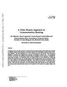
will be returned to the source along the source route traced by the RREQ packet. Once the RREP reaches the source, the route discovery phase is over and the route maintenance phase begins. Due to mobility, the route between two cars is subject to frequent breaks. Thus, during an ongoing data transfer, periodic Route Checks are performed. If any check fails the route maintenance phase is over and a new route discovery phase begins. The advantage of performing a new route discovery rather than a expensive route recovery is that the new route is exploits the current traffic conditions within the Sector, providing a more robust path that in most cases remains valid for a longer period of time. The above description focuses on Vehicle-to-Vehicle (V2V) communications. Vehicle-to-Infrastructure (V2I) communications are a special case of V2V. Likewise, communications between two vehicles within the same Sector are a special case of the above. Once the associated CRP detects that the destination is registered in the same Sector, it takes no action. Thus the destination itself, upon being discovered by the RREQ will return the RREP directly to source. In this case the route is entirely wireless. TrafRoute can seamlessly handle any of the cases described above without requiring any change to its functionality. III. P ROTOCOL D ETAILS A. Forwarding Points Given the intrinsic broadcast nature of the wireless channel, to efficiently disseminate information along wireless ad hoc networks, it is best to restrain the transmissions to a portion of relay nodes without reducing the connectivity of the network. A key concept used by TrafRoute is the efficient forwarding scheme that takes into account the topological characteristics of the road network. In fact, we can define a set of geographic locations that are strategically chosen to reduce the set of forwarding nodes. We can then force the vehicles to act as forwarders only if they are in one of these locations. In the remainder of this paper we will refer to these locations as Forwarding Points (FP). The best strategy to adopt is to try to geographically cover the entire network with the smallest possible number of FPs without compromising the overall connectivity of the network. In order to do so we must consider the nature of urban propagation. The spectrum of VANET standards only allows Line of Sight (LoS) communications with few obstacles in between. The presence of road obstacles (buildings, trees etc.) strictly limits the signal propagation along a road segment. As a consequence, the graph restricted to vehicles at intersections is almost as connected as the full graph including all the vehicles. We therefore pick as FPs all the road intersections. To our favor, it is well known that road intersections and traffic lights tend to create dense vehicles clusters [4]. These clusters are thinly connected to each other through much more dispersed vehicles along the road segments [5]. Moreover, most road intersections are within radio range of each other. In Figure 1 we show the cumulative distribution of the distance between two connected intersections, for the whole Los Angeles County, extracted
Cumulative Distribution Function
3
1 0.8 0.6 0.4 0.2 Cumulative Distribution
0 0
200
400
600
800
1000
Connected intersection distance
(a) Orthogonal junction
Fig. 1. Cumulative distribution of distance between connected intersections for the Los Angeles County, California.
from the TIGER database [6]. We can observe that more than 90% of the intersections are less than 300 meters apart. Commercial IEEE802.11b/g cards can easily bridge such distances in line of sight. However it is possible that a road segment may be longer than the LoS maximum distance at which two nodes can communicate. In this case, some geographic areas would remain uncovered, requiring the placement of additional FPs where needed. TrafRoute requires each node to know its own position and therefore some sort of navigation device. However the list of FPs and their properties can be defined in advance and then distributed to the vehicles (for example it could be downloaded from the Internet using 3G). Therefore the protocol does not depend on the map information that might have different accuracy for different versions and providers. Every FP is defined by a unique ID that is built concatenating its home Sector ID and an incremental ID that identifies it within the Sector. Each FP is characterized by its geographical coordinates lon, lat, the IDs of the neighboring FPs and the minimal forwarding radius rmin . One of the key concepts introduced by TrafRoute is the forwarder self-election based on the distance from the closest FP. As we will see in section III-B, rmin plays a key role in the forwarder self-election procedure. Therefore, we set the value of rmin to be proportional to the size of either the intersection or the road the FP lies on, as presented in Equation 3. q 2 in 2 (Lin min ) + (Lmax ) q 2 out 2 = (Lout min ) + (Lmax )
αin = αout
(1) (2)
1 · (αin + αout ) · Lwidth (3) 2 As we can observe from (1) and (2) the value of rmin considers the number of lanes entering (Lin ) or leaving (Lout ) an intersection. In particular, if more than two roads are intersecting, only the biggest, that defines Lmax , and the smallest, that defines Lmin , are taken into account for the computation of rmin . In (3) the coefficients obtained in (1) and (2) are averaged out and multiplied by the lane width (Lwidth ). The resulting area covers the center of the intersection as shown in Figure 2(a). Moreover, the geometrical center of the FP is located at the intersection of the virtual lines that divide rmin =
(b) Non-orthogonal junction
Fig. 2. Representation of a FP for different junction types. The inner circle represents the area in the rmin radius, while, the larger one the area in the rmax radius.
each road in half. It is worth saying that while in orthogonal junctions this coincides with the center of the intersection, as shown in Figure 2(a), if two streets meet at an angle, the center of the FP will not be the point of contact between the two roads, but will be in the position that ensures LoS with adjacent FPs, as shown in Figure 2(b). B. Neighboring and Forwarder Self-election In TrafRoute each vehicle is a potential forwarder, thus to be able to perform the routing decision each vehicle must obtain information about its neighborhood. In order to keep this information as fresh as possible, each node periodically broadcasts a HELLO packet containing the following information: a FP ID field, containing the identifier of the closest forwarding point; a Forwarder Flag, consisting of a single bit representing the result of the forwarder self-election procedure; a Sector ID, identifying the geographical area in which the node is currently located; and finally, a Penetration Index (PI), representing the number of distinct FPs that the vehicle can reach. The PI is calculated counting the number of distinct neighboring FPs covered by a least one forwarder. Each vehicle stores the information about its neighbors in a table that is refreshed upon receiving a new HELLO packet. After a defined timeout period in which no HELLO packet has been received from a particular vehicle, the entry is deleted from the neighboring table. Using both, its location and neighboring information each vehicle performs the forwarder self-election procedure that will determine whether it will act as a relay or not. Each vehicle finds the closest FP and computes its distance d from it. A vehicle always elects itself as a forwarder if d < rmin , where rmin is associated with the closest FP. As discussed in section III-A, if a vehicle is within a radius rmin from the FP it means that it is in an advantageous position that allows to connect to other FPs. For sparse traffic scenarios there might not always be a vehicle within rmin distance from a FP. In fact, there may be nodes just outside of rmin . In that case, none of the nodes would become a forwarder, thus limiting the connectivity of the network. To prevent this from happening, we extend the forwarding area beyond the actual crossing, including potential forwarders located on the edge of the intersection (e.g. cars waiting at a red light). However, as we increase the distance from the intersection, the connectivity
4
dref = rmin + ∆r(N, N )
(4)
With ∆r(N, N ) being calculated as follows: N
∆r(N, N ) = rmin · (N − 1)− β
(5)
A vehicle only elects itself as a forwarder if its actual distance to the nearest FP is smaller than dref . In Figure 3 we introduce the ratio Rd = ∆r(N, N )/rmin as a function of the current number of neighbors for different neighbor averages. Rd represents how dref is close to rmax ; its value is 0 when dref = rmin and it is 1 when dref = rmax . The parameter β is a normalization factor. For our simulations, we choose β = 50 as this will result in having Rd quickly tend to 0 for dense traffic scenarios, whereas in sparse traffic scenarios, Rd decreases only slowly and thus increases the forwarding area as shown in Figure 3. The choice of β very much depends on the application and traffic scenario. For general urban traffic, we found that β = 50 provides the best results. As we can observe, for an increasing current number of neighbors, the reference distance from the FP center decreases. In fact, when there are many neighbors around a vehicle, it is more likely that at least one is in a better position, i.e. closer to the center of the intersection. Conversely, a small number of neighbors implies that the chances to have a vehicle in a better position are much lower, then the reference distance will be close to rmax . In addition, Figure 3 shows the impact of the neighbor average N . A low value of N implies a low density of vehicles in the local area, thus the reference distance is close to rmax regardless of the current number of neighbors. Vice versa, high values of N imply high local density thus requiring to set the reference distance very close to rmin in order to have few, but well placed forwarders. C. Route Discovery When a node wants to initiate a new connection, it issues a new Route Request (RREQ) packet. Each RREQ has a unique identification number that is obtained combining the source address and a locally generated forwarding ID. RREQ packets are disseminated along the network, using broadcast. In order to distribute the RREQs in an efficient way, vehicles are allowed to re-broadcast the packets only if they are forwarders,
1 0.8 0.6 Rd
to cars located on intersecting roads quickly drops, due to the surrounding buildings. Therefore we also allow vehicles to become forwarders if they are located at a distance from the closest FP between rmin and rmax = 2 · rmin . However, allowing all vehicles in this area to become forwarders regardless of the local density would result in a too large number of forwarders. A good estimate of the local density would be the current number of neighbors N . However, interference and collisions often cause the loss of HELLO packets, therefore the instantaneous number of neighbors is subject to sharp peaks and drops. For this reason each node also keeps track of the average number of neighbors N over the last 10 seconds. N provides a good estimate of the density of vehicles in the surroundings. Each vehicle then independently computes the following reference distance:
0.4 0.2 0 5
10
15
20
25
30
35
40
45
50
Current Number of Neighbors Neighbor Avg. 2 Neighbor Avg. 10
Neighbor Avg. 20 Neighbor Avg. 50
Fig. 3. The different curves show Rd as a function of the current number of neighbors (N ) for several neighbor averages (N ).
and each specific RREQ is only re-broadcasted once. RREQ packets are also scoped to the Sector they were generated in, meaning that nodes outside the Sector where the RREQ was generated will just discard the packet. As the RREQ packet will cover the entire Sector, it will reach the Sector CRP. If the CRP recognizes that the destination is in another Sector, it will forward the RREQ to the corresponding CRP; it will discard the packet otherwise. At each re-transmission of the RREQ each forwarder adds its current FP ID to the packet. The sequence of traversed FPs constitutes the path that will be used to route the packets between source and destination. To avoid the use of unreliable links, forwarders are only allowed to rebroadcast RREQ packets that are received from neighboring FPs, i.e. separated by a single road segment. Once the destination receives the RREQ it will issue a Route Reply (RREP) packet containing the inverse FP path and send it back to the source using unicast. The RREP will be forwarded back to the source following the same scheme as data packets. If the source node does not receive the RREP packet after a timeout period, a new route discovery is issued. D. Data Transfer and Route Check After a successful route discovery, both source and destination nodes have a valid communication path. This route is composed out of FP IDs that need to be traversed by each packet. A small header, containing the sequence of FPs, is added to each data packet. At each forwarding step, the forwarding node chooses the next hop among its neighbors that are on the next FP and have elected themselves as forwarders. If there is more than one eligible node, the one with the highest penetration index is selected as next hop. In addition, every intermediate hop checks if the destination is among its neighbors. If so, it directly delivers the packets to the destination. This might happen if the destination node moves along the transmission path in direction of the source node. The forwarding choice is performed in a per-packet fashion, i.e. each time a packet needs to be forwarded, the forwarding node will perform the choice. Hence, subsequent packets might be forwarded to different nodes although they are on the same FP, thus increasing the reliability of the perhop transmission.
5
IV. E VALUATION In this section we present an evaluation of the performance of TrafRoute carried out through simulation. All of the following results were obtained using the same simulation framework. The simulation framework consists of three main components: VERGILIUS [7], CORSIM [8] and QualNet [9]. In particular we used VERGILIUS to extract the map information from the TIGER database [6] and to build the mobility scenario. We then used CORSIM to obtain a mobility trace that was processed again by VERGILIUS in order to obtain the signal attenuation between nodes. Indeed VERGILIUS implements the validated propagation model, presented in [10], that takes into account the presence of buildings hence increasing the realism of the simulations. We then used QualNet to perform the network simulations using IEEE802.11b and the standard transmitted power of 15 dBm. A. Forwarding Points Our first evaluation study investigates how increasing vehicle density affects the forwarding scheme. For this study, we used a 500x500m road network, containing 30 FPs. Realistic mobility scenarios have been generated using the tools referenced previously. As explained in section III-A, every vehicle independently elects itself as a forwarder if its location and neighboring information meet the requirements. Figure 4 shows the average ratio of forwarders at every FP for growing vehicle density. We refer to Average number of nodes as the number of vehicles that are inside the map at each second, averaged over the duration of the simulation. For a very sparse traffic scenario the number of FPs having no forwarder does not exceed 30%. Having at least one forwarder
at the remaining FPs will in most cases result in a successful communication. Please note that due to the mobility of the cars, some FPs located on less crowded intersections are sometimes empty even for the dense mobility scenarios. This does not affect the performance of the forwarding scheme. Indeed, it enforces the use of the strong communication path over the crowded main roads. With a growing vehicle density, the number of FPs having more than one forwarder grows as the probability of having a car within an FP grows at the same time. However, the number of forwarders will not exceed a certain threshold as the number of cars momentarily located at a FP is limited. In addition, for every simulated scenario, the elected set of forwarders within every FP is sufficient to interconnect the entire network. 1 0.8 Portion of FPs
During an ongoing communication the source node periodically issues a Route Check (RCHECK). The purpose of the route check is to make sure that the packets are actually getting delivered providing transparency to upper layers. For example, in the case of a UDP connection, the source keeps generating packets and does not check if any of them gets delivered. If the connection drops, the sending node is not aware of it and therefore, the transmission of packets results to be not only useless, but also a waste of resources. The RCHECK procedure consists of sending a small packet along the path. The destination will then reply with a RCHECK Reply Packet. If the source node does not receive a reply within a timeout period, the path is dropped and a new route discovery is initiated. Performing a new route discovery every time a RCHECK fails provides a fresh path that is also the most reliable at that moment. Another approach could be to perform periodic Route Updates during ongoing data transfers. However, Route Updates could only be performed taking into account information available either at the source or at the destination. Not considering the variation of traffic conditions along the path, would likely result in a very unreliable route. Performing a new route discovery is not more expensive and exploits the global traffic conditions in the current Sector, providing a more robust path, that in most cases remains valid for a longer period of time.
0.6 0.4 0.2 0 60
80
100
120
140
160
180
200
220
Average Number of Nodes 0 Forwarders
Fig. 4.
1 Forwarder
>1 Forwarders
Average Number of Forwarders at each FP.
B. Route Discovery In this section we are interested in evaluating the performance of the route discovery. In fact, while most of the geographic routing protocols assume to know a priori the position of the destination vehicle by mean of a location service, TrafRoute autonomously finds the route to destination, thus obtaining the best and most updated one. The route discovery simulations have been performed on the same map scenario used in Section IV-A. For an increasing average number of cars, two performance metrics have been evaluated and compared to the discovery procedure of AODV [11]. In order to obtain comparative results, the source and destination have been chosen on the same road segment for every simulation. Figure 5 shows the discovery delay with a confidence of 90% for an the increasing node density, i.e. the time elapsed at the source node’s side between sending the RREQ and receiving the RREP. Please note that the vehicular distribution slightly varies for every density scenario, making some scenarios more efficient than others (e.g. more cars located at strategic intersections). The standard discovery procedure employed by AODV performs a ring search, i.e. the lookup perimeter is increased every time the destination cannot be found. As a result, the average discovery delay considerably increases with a growing distance between source and destination. The use of AODV in flooding mode provides slightly better results in terms of
6
delay, but has a much higher cost in terms of exchanged packets. As shown in Figure 6, the discovery overhead of both AODV methods is much higher than using TrafRoute, mainly because the route requests are re-broadcasted by every vehicle in the network, which often results in poor network performance [12]. However, the main advantage of the TrafRoute discovery procedure is that the resulting path is not bound to specific nodes. As discussed in Section III-C, the route follows a sequence of landmarks (FP IDs), making the path much more robust to mobility as compared to AODV. 700
TrafRoute AODV-Flood AODV-Ring
600 Delay [ms]
500 400 300 200 100 0 60
80
100
120
140
160
180
200
220
Average Number of Nodes
Number of Discovery Packets
Fig. 5. Route Discovery delay as a function of vehicle density for AODV and TrafRoute.
250 200
TrafRoute AODV-Flood AODV-Ring
150 100 50 0 60
80
100
120 140 160 Average Number of Nodes
180
200
220
Fig. 6. Number of packets generated by the route discovery procedure as a function of the vehicle density for AODV and TrafRoute.
C. Route Usage In this section we present the advantage of using a source routing approach as opposed to a stateless geographic approach adopted by many routing protocols for VANET. For this purpose we built two different mobility scenarios over the same road topology (see Figure 7). The two scenarios have the same average density of vehicles, but the distribution of the vehicles on the road is different. In particular, scenario A considers a “uniform” distribution of vehicles on the map, while scenario B considers a higher density of vehicles along the main roads. We chose two locations on the map, S and D on the edge of one of the main roads. Every second of the simulation the closest vehicle to S transmits a packet of 128 bytes to the vehicle that is closest to D. In Figure 7, we show the resulting routes for TrafRoute and GPSR [13]. The blue solid lines represent the successfully delivered packets and the red dashed lines represent the dropped packets.
It is evident from Figures 7(c) and 7(d) that TrafRoute dynamically adjusts to the different vehicle density and, in this case, chooses a longer but more reliable path. Figures 7(a) and 7(b) instead show that the geographic approach has two main disadvantages. First, the geographically shortest path often involves the use of links that cut the corners of the streets. These links are often very weak and thus unreliable for long data transfers. Instead, TrafRoute mainly uses LoS links that are stronger and thus more reliable. Second, since the routing is performed using only a local knowledge of the network, the route often encounters dead ends, triggering the recovery procedure that is not efficient in urban scenarios. These considerations are true not only for GPSR that is one of the simplest geographical routing protocols, but also for more complex geographical routing protocols. Considering Figures 7(a) and 7(b), since D is located south of S, the packets are forwarded in that direction as soon as there is the chance. In fact, many packets follow the first road that heads south, which turns out to be a dead end. A more complex geographic routing scheme would build the route computing the whole path from S to D. Such approach would instead choose the second road that turns south, a solution that could work for scenario A, but not for scenario B. In conclusion, for urban scenarios, that often present an uneven distribution of vehicles, it is more desirable to have knowledge of the complete path between source and destination, making of source routing a better candidate. D. Data Transfer In this section we evaluate the performance of an ongoing data transfer using TrafRoute. Two scenarios have been simulated; a transmission where both vehicles are in the same Sector (intra-sector); and a remote transmission where the vehicles are in two different Sectors (inter-sector). The remote transmission uses roadside units (CRPs) to relay the data. For every scenario, we used 500x500m Sectors containing an average number of 140 cars. Figure 8 shows mobility paths of the source and destination node for both scenarios. A 60 second CBR flow has been used as evaluation application. As shown in Table 1, for the inter-sector scenario TrafRoute obtains a slightly higher delivery ratio despite a higher average number of hops. The reason for this counterintuitive result is the higher stability of the path, as it involves two static nodes. In fact, this also reflects on the higher number of successful route checks. As we can see from Table 1, the delivery ratio at the application layer is lower than at the network layer. This is due to the fact that at the destination, packets may arrive out of sequence. As TrafRoute uses virtual routes, it is possible that subsequent packets take different routes, resulting in different end-to-end delays and consequently out of sequence delivery. However, considering the harsh mobility scenario, assuring packet ordering might result in a waste of resources. Packet drops only occur if there is no suitable forwarder at an FP along the route. As the path from the source to the destination is virtual, the critical part of the route is the last hop as the
7
(a) GPSR — Scenario A Fig. 7.
(b) GPSR — Scenario B
(c) TrafRoute — Scenario A
(d) TrafRoute — Scenario B
Route comparison between TrafRoute and GPSR for two scenarios with different distribution of vehicles (uniform and non-uniform).
destination might have moved out of the transmission range of the last FP. However, if the destination node moves towards any FP along the route, it will still be able to receive the packets as the protocol checks if the destination is in the neighborhood at every hop. In order to keep the control overhead as low as possible, periodical route checks (RCHECK) are only initiated for active data transfers. For both simulated scenarios, approximately one third of the initiated RCHECKs were successful, keeping the route active. The remaining unsuccessful RCHECKs trigger a new route discovery, providing a fresh path between the source and destination. As described in section III-D, a new route discovery provides a more robust path introducing a fairly low overhead. The high variance of the end-to-end delay is caused by the buffering of packets at the source during the discovery phase and in case no suitable forwarder is found on the first FP. The buffered packets will only be sent out once a new route has been established or if a new forwarder becomes available at the first FP. Nevertheless, delays of several seconds remain an exception as the average delay is around 100ms for both scenarios. Please note that for the computation of the endto-end delay in the inter-sector scenario, we did not take into account the time overhead introduced by the DHT to find the Sector where the destination car is located.
(a) Intra-sector Paths Fig. 8.
(b) Inter-sector Paths Mobility Scenario
V. R ELATED W ORK Over the last few years, different approaches have been proposed to perform routing in vehicular networks, in this section we review the most popular. The majority of them use stateless geographic routing to transmit data. This implies the use a location service to retrieve the position of the destination. To the best of our knowledge, none of the following routing
TrafRoute Delivery Ratio CBR Delivery Ratio Packet Drop on Route Ratio Packet Drop on Last Hop Ratio RCHECK initiated Successful RCHECK End-to-End Delay [ms]
Number of Hops
Intra Sector 0.74 0.61 0.058 0.044 12.9 4.2 Min: 9 Max: 2241 Avg: 85 Min: 2.7 Max: 5.1 Avg: 3.9
Inter Sector 0.83 0.69 0.065 0.001 12.3 5.3 Min: 17 Max: 5532 Avg: 102 Min: 5.0 Max: 6.1 Avg: 5.5
TABLE I T RAF ROUTE P ERFORMANCE M ETRICS
protocols has been evaluated in conjunction with a location service. In addition, it could not be verified if a realistic simulation environment has been used to evaluate the protocols, which, as shown in [14], heavily influences the results. In GyTAR [15] the routes are built following a greedy procedure that finds the best sequence of intersection that connects source and destination.The best sequence of intersections is progressively built choosing the next-hop vehicle, at an intersection, according to its speed and direction but also to the vehicle density between the current intersection and the one relative to the candidate next-hop. Similarly, the LOUVRE [16] creates an overlay network on top of an urban topology based on the traffic density between two overlay nodes (defined by intersections). The computation of the traffic density on a road segment is distributed among the vehicles passing over it and the overlay link state routing table is constructed using the Dijkstra algorithm. The packets are then forwarded in a greedy stateless fashion towards the destination. A greedy procedure progressively selects the locally optimal path. However, the locally optimal path might not be the globally optimal. In contrast, TrafRoute uses the globally optimal path, as demonstrated in section IV-C. The idea of Sectors in vehicular networks is not new. For example, in RAR [17] vehicles affiliate to Sectors (that are composed of and managed by several roadside units). Connection between vehicles are created exploiting the infrastructure and without using hierarchical addressing. RAR works in a V2I2V fashion, thus limiting multi-hopping. This allows to minimize
8
the packet loss and to decrease the delay because routing will be handled by the infrastructure. The main drawback of this approach is that it requires the installation of a great number of roadside units, which is highly expensive and not feasible in all the cities. In our approach we use infrastructure only if vehicles belong to different sectors, thus limiting the number of roadside units. CAR [18] is a protocol that integrates locating destination with finding connected paths between source and destination. After finding a path, it is auto-adjusted on-the-fly by vehicles on the path. During the path discovery, nodes add an anchor, indicating positions and velocity vectors of the current and previous forwarder, to a broadcast packet in their direction if different from the previous forwarder. This method is very similar to marking the path by listing the FP IDs. In fact, in theory, the direction of the velocity vectors change only when intersections are found and the packets travel on a different road segment. However, this method is prone to errors due to the accuracy of the velocity vectors. In fact, an anchor is added whenever two velocity vectors are parallel. In a realistic scenario, due to error positioning, this might not always happen even for vehicles traveling on the same lane of the same road. Therefore, the overhead of the packet might grow considerably. VI. C ONCLUSION AND F UTURE W ORK In this paper we presented TrafRoute, a routing protocol for vehicular networks that implements an innovative forwarding scheme that involves self-election based on position, knowledge of the road topology and node density. TrafRoute implements virtual routes, made out of FPs rather than of actual vehicles, that are much more durable and reliable. Routes are built on demand considering the current vehicular traffic density. Using CRPs, the pool of vehicles that can efficiently communicate with each other can be extended to geographically distant areas. Performance evaluation shows that TrafRoute introduces a low control overhead and provides robust communication paths that achieve high delivery ratios. Future work will focus on a more detailed study on the benefits of landmark-based source routing and provide a comparison with stateless geo-routing protocols and the overhead introduced by the mandatory use of location services. ACKNOWLEDGMENT Raphael Frank would like to thank the National Research Fund of Luxembourg (FNR) for financially supporting this work. Eugenio Giordano would like to thank Microsoft Research for financially supporting this work through its PhD Scholarship Programme. Pasquale Cataldi wishes to acknowledge the European Commission for their support by partially funding this work work through the FP7 ICT Project iTETRIS (No. FP7 224644). R EFERENCES [1] B. Karp and C. Berkeley, “Challenges in geographic routing: Sparse networks, obstacles, and traffic provisioning,” in Presentation at the DIMACS Workshop on Pervasive Networking, 2001.
[2] K. C. Lee, P.-C. Cheng, J.-T. Weng, L.-C. Tung, and M. Gerla, “VCLCR: A practical geographic routing protocol in urban scenarios.” UCLA Computer Science Department, Tech. Rep. TR080009, 2008. [3] M. Gerla, B. Zhou, Y. Lee, F. Soldo, U. Lee, and G. Marfia, “Vehicular grid communications: the role of the internet infrastructure,” in Proceedings of the 2nd annual international workshop on Wireless internet. ACM New York, NY, USA, 2006. [4] A. Mahajan, N. Potnis, K. Gopalan, and A. Wang, “Evaluation of mobility models for vehicular ad-hoc network simulations,” in IEEE International Workshop on Next Generation Wireless Networks (WoNGeN), 2006. [5] M. Fiore and J. H¨arri, “The networking shape of vehicular mobility,” in Proceedings of the 9th ACM international symposium on Mobile ad hoc networking and computing. ACM New York, NY, USA, 2008, pp. 261–272. [6] Census, “Topologically Integrated Geographic Encoding and Referencing system,” http://www.census.gov/geo/www/tiger/, Last Accessed in July 2009. [7] E. Giordano, E. D. Sena, G. Pau, and M. Gerla, “Vergilius: A scenario generator for vanet,” in 2010 IEEE 71st Vehicular Technology Conference: VTC2010-Spring, 2010. [8] University of Florida, “Traffic Software Integrated System - Corridor Simulation,” http://mctrans.ce.ufl.edu/featured/tsis/, Last Accessed in July 2009. [9] Scalable-Networks, “QualNet Network Simulator,” http: //www.scalable-networks.com, Last Accessed in July 2009. [10] E. Giordano, R. Frank, G. Pau, and M. Gerla, “CORNER: a Realistic Urban Propagation Model for VANET,” in Proceedings of Seventh IEEE International Conference on Wireless On-demand Network Systems and Services (WONS 2010). IEEE, February 2010, pp. 99–105. [11] C. Perkins and E. Royer, “Ad-hoc on-demand distance vector routing,” in proceedings of the 2nd IEEE Workshop on Mobile Computing Systems and Applications, vol. 2, 1999, pp. 90–100. [12] S.-Y. Ni, Y.-C. Tseng, Y.-S. Chen, and J.-P. Sheu, “The broadcast storm problem in a mobile ad hoc network,” in MobiCom ’99: 5th annual ACM/IEEE international conference on Mobile computing and networking. New York, NY, USA: ACM, 1999, pp. 151–162. [13] B. Karp and H. Kung, “GPSR: greedy perimeter stateless routing for wireless networks,” in Proceedings of the 6th annual international conference on Mobile computing and networking. ACM New York, NY, USA, 2000, pp. 243–254. [14] E. Giordano, R. Frank, A. Ghosh, G. Pau, and M. Gerla, “Two Ray or not Two Ray this is the price to pay,” in Proceedings of Sixth IEEE International Conference on Mobile Ad-hoc and Sensor Systems (MASS 2009), October 2009. [15] M. Jerbi, R. Meraihi, S. Senouci, and Y. Ghamri-Doudane, “GyTAR: improved greedy traffic aware routing protocol for vehicular ad hoc networks in city environments,” in Proceedings of the 3rd international workshop on Vehicular ad hoc networks. ACM New York, NY, USA, 2006, pp. 88–89. [16] K. Lee, M. Le, J. Haerri, and M. Gerla, “Louvre: Landmark overlays for urban vehicular routing environments,” Proceedings of IEEE WiVeC, 2008. [17] Y. Peng, Z. Abichar, and J. Chang, “Roadside-aided routing (RAR) in vehicular networks,” in IEEE International Conference on Communications, 2006. ICC’06, vol. 8, 2006. [18] V. Naumov and T. Gross, “Connectivity-aware routing (CAR) in vehicular ad-hoc networks,” in IEEE INFOCOM 2007. 26th IEEE International Conference on Computer Communications, 2007, pp. 1919–1927.