Computer specialists are rarely trained in the world of tracks and trains, while signaling experts are ... which is very close to the PLC source code. The coding of the ..... [7] Fagan, M.E.: Design and Code Inspections to Reduce Errors in Program.
Computers in Railways XI
651
Train control language – teaching computers interlocking J. Endresen1, E. Carlson1, T. Moen1, K. J. Alme1, Ø. Haugen2, G. K. Olsen2 & A. Svendsen2 1 2
ABB, Bergensveien 12, 1375 Billingstad, Norway SINTEF, Forskningsveien 1, Oslo, Norway
Abstract Computer specialists are rarely trained in the world of tracks and trains, while signaling experts are rarely computer specialists. This paper is about bridging the gap between trains and computers with a specially designed language that enables the signaling experts to create consistent train interlocking systems. The language is supported by tailored tools created with open source technology on the development platform Eclipse. From the formal definition of the language in the form of a metamodel, a graphical editor is generated. The systems created with that graphic editor are then transformed for several purposes that are internally consistent. The editor makes sure that the systems conform to the language, and the language makes sure that the systems conform to the way interlockings are designed. The transformations then produce interlocking tables and even actual code automatically from the graphically created model. Keywords: interlocking, Computer Based Interlocking (CBI), code generation, Domain Specific Language (DSL), eclipse.
1
Introduction
A railway interlocking system is a system that prevents conflicting and dangerous train movements through a network of tracks and ensures that no clear signal is given to a train unless the requested route is safe and locked. Today all new interlocking systems are computer based (CBI). Configuring the interlocking system for a particular station has been a manual process requiring multiple steps from creating and verifying the requirements (e.g. interlocking tables) to validating the final code. This paper describes a Domain Specific WIT Transactions on The Built Environment, Vol 103, © 2008 WIT Press www.witpress.com, ISSN 1743-3509 (on-line) doi:10.2495/CR080631
652 Computers in Railways XI Language for specifying stations and to allow automatic generation of interlocking tables and the code for the CBI etc. This Train Control Language will improve the completeness and consistency of the specifications and reduce the human effort.
2
Current CBI development process
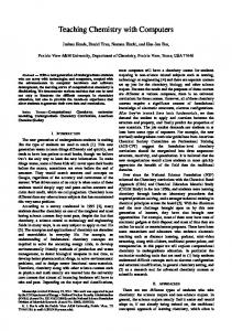
ABB’s Computer Based Interlocking is a hardware redundant programmable logic controller (PLC). The two PLC’s have diversified code called A and B to enhance the safety of the system. The current workflow for developing a specific CBI is illustrated in Figure 1. Note that the figure shows the basic workflow and not all the details. Input requirement specification Train routes Interlocking tables National rules
Functional specification
Formal review of Functional specification
Design specification
Formal review of tools and libraries (not repeated for every CBI)
Program A
Program B
Integration test of A and B
Factory Acceptance Test
Site Acceptance Test
Figure 1:
Workflow for developing a specific CBI.
The input requirement specification is made up of two parts: One part is the customer’s and the other is the generic CBI specification. The customer’s parts contain drawings showing the structure of the station with its basic elements (tracks, switches, signals, track circuits, derailers etc.) and train routes and interlocking tables. The interlocking tables are basically a set of Boolean equations for what needs to be true before allocating a route to a train. The national rules must also be incorporated into the CBI. From the above inputs ABB generates a functional specification, which is a mapping of the interlocking tables into a set of logical equations for the CBI. WIT Transactions on The Built Environment, Vol 103, © 2008 WIT Press www.witpress.com, ISSN 1743-3509 (on-line)
Computers in Railways XI
653
This process is manual and hence it is susceptible to errors. To ensure that the functional specification is correct it is formally but manually reviewed, often by the customers themselves. The functional specification is further refined into the design specification, which is very close to the PLC source code. The coding of the PLC is done by selecting parameterized functional blocks. The development of the design specification and the programming of the PLC are both manual operations. The development of the A and the B code are done by two separate teams with different tools and libraries in order to reduce the probability of common mode failure. The libraries incorporate the national rules. The functional specification, tools and libraries are formally reviewed according to the Fagan inspection method [7]. This is a structured method for finding errors in documents such as specifications, programming code and designs. The method is good for finding inconsistencies and errors, but timeconsuming. The PLC code is tested at three separate levels. The Integration tests reveal among other things the different interpretations of the specifications by the two development teams. The Factory and Site Acceptance tests ensure the conformance to the input requirement specifications. ABB and SINTEF (the largest independent research organization in Scandinavia) have developed a Domain Specific Language (named “Train Control Language”) for specifying CBI’s and automating the above process. The vision was to be able to combine the station drawing with the train routes and interlocking tables in the TCL. From the models created in the TCL language, the PLC code and test cases should be automatically generated. In the future the TCL could be used by the customers eliminating one more manual step.
3
Domain specific modeling languages
Domain specific languages (DSL) can be seen as bridges between the experts of an application domain and the experts of computer science. Application designers and programmers need to be experts in modeling and programming and they need to be experts in the application domain to be able to know what to describe for the computer. Since the computer science knowledge requires a specialist education in itself, the designers of applications are most often computer specialists with an additional education in the area of the application. Creating a DSL is a way to make it possible for application domain experts to become designers of the applications with no loss in generality or efficiency. The application domain experts will design the application by using the DSL while the computer specialists are responsible for implementing the DSL with supporting tools. The DSL must be created and this requires close cooperation between computer language experts and domain experts. When the DSL has been created and the supporting tools have been produced, the application specialists can apply the language to design new applications. The idea is that we now see other persons making the applications. Application experts with little knowledge of modeling should be able to produce computer WIT Transactions on The Built Environment, Vol 103, © 2008 WIT Press www.witpress.com, ISSN 1743-3509 (on-line)
654 Computers in Railways XI based systems. The computer language specialists will concentrate on improving the tool implementations and the code automatically generated from the DSL editors.
4
Train Control Language (TCL)
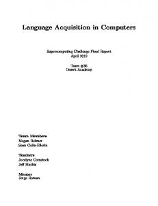
We shall now walk through the definition of a DSL called TCL, Train Control Language. The purpose of the language is to define train stations from the point of the interlocking. 4.1 Defining TCL The definition of a DSL is done through a metamodel. A metamodel is a model of the language. It defines the language concepts and the relations between these concepts. Typically we apply class diagrams from UML [9] to define metamodels. UML is a general modeling language. Figure 2 shows one small part of the TCL metamodel that we shall use to explain the essence of metamodeling. A Station has a name and it contains Tracks, TrackCircuits and Stillers (local route setting device). A station contains even more objects, but they are not included in our extract in Figure 2. Each of these concepts (or “metaclasses”) contains attributes that describe values that add to their definition. Tracks have a name, a length, a gradient and speed limits.
Figure 2:
A small piece of the TCL metamodel.
WIT Transactions on The Built Environment, Vol 103, © 2008 WIT Press www.witpress.com, ISSN 1743-3509 (on-line)
Computers in Railways XI
655
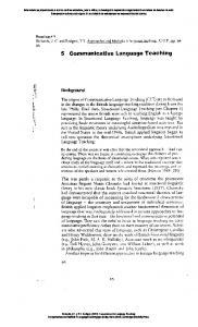
We also notice the relation (association) between TrainRoute and TrackCircuit. This relation describes that a TrainRoute involves a number of TrackCircuits. Thus we have explained three important characteristics of a metamodel, namely the composition (Stations contain TrackCircuits etc.), attributes (Station has a name) and relations (TrainRoute refers to a number of TrackCircuits). In Figure 3 we show how conceptual generalization hierarchies are described in the metamodel. A Switch is a special type of Track and Switches come in two variants, RemoteSwitches and ManualSwitches. The point of defining such inheritance hierarchies is to define similarities between concepts and this will normally make the language description more compact and concise. Whatever we define for all Tracks should also hold for all Switches.
Figure 3:
Track inheritance hierarchy.
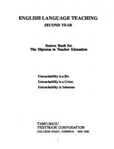
In order to show the overall complexity of a metamodel for a fairly simple language we present the full TCL metamodel in Figure 4 even though the texts are barely readable. As a comparison a general purpose modeling language like UML will have hundreds of metaclasses. Since TCL is developed exclusively for this domain, the level of abstraction can be raised and a more precise model of the train domain can be produced. The metamodel defines the terms of the language and the logical way they connect together. In fact the metamodel is a model of the internal representation of some description in the DSL. But the metamodel says neither in itself anything about how the language will appear for the user, nor what the meaning WIT Transactions on The Built Environment, Vol 103, © 2008 WIT Press www.witpress.com, ISSN 1743-3509 (on-line)
656 Computers in Railways XI
Figure 4:
The whole TCL prototype metamodel.
of the terms should be. In other words for the TCL we do not yet know how we would recognize a Switch in a description of a Station, and we do not really know what a Switch is meant to be or do. 4.2 The concrete syntax of TCL We have now presented the metamodel of TCL, but we want to know how the terms will appear for the TCL users. This is what we call concrete syntax of the language. We need to determine whether we want to define train stations in a graphic way or through lines of text. We have chosen to define train stations graphically. The basic technology that we have used to define TCL and its supporting tools come from the open source community eclipse.org and its modeling framework EMF [5]. There exists an umbrella over EMF called GMF [4] that can be used to define the graphics of the terms of the metamodel. For each of the metaclasses symbols and connections are defined and associated with the respective metaclasses. For TCL a description of a train station will look as depicted in Figure 5.
Figure 5:
Concrete graphic TCL of a train station.
WIT Transactions on The Built Environment, Vol 103, © 2008 WIT Press www.witpress.com, ISSN 1743-3509 (on-line)
Computers in Railways XI
657
In fact the GMF technology helps produce an editor for TCL based on the metamodel and the graphic definitions. This editor is embedded into the eclipse environment. 4.3 The semantics of TCL Now we have an editor and we have a definition of the abstract and concrete syntax of TCL. We still do not know what the meaning of our drawings is. Given that the notation has been taken from traditional train notations, the computer generated drawings could be used to communicate between train specialists that have a prior understanding of these symbols. This is not, however, our main goal. We want to use TCL to make the signaling experts able to design the interlocking systems all the way such that the interlocking systems will actually work safely without having to bring in programmers to interpret the signaling experts’ designs. What we need is to define the meaning of the TCL language and we do that by defining how to generate interlocking code directly from the TCL descriptions. To define the code generators we use the tool MOFscript [6, 8] that have been developed at SINTEF. To give an idea of what this code generation definition look like, we show in Figure 6 a piece of a MOFscript program. The MOFscript program contains 'Togvegsperrefunksjon for skifteveg (Tsp.' cName')\n\n' 'Gren_1_Tsp.' cName '\n' 'Boolsk uttrykk:\n' 'Gren_1_Tsp.' cName '\t= TO.Tsp.' cName ' * Tsp.H' startName '/' if (tr.routeName.size() > 2){ //if not fik.sign: print an extra 'H' 'H' } endName '\n\n' 'Gren_2_Tsp.' cName '\n' 'Boolsk uttrykk:\n' 'Gren_2_Tsp.' cName '\t= Tsp.H' startName '/' if (tr.routeName.size() > 2){ //if not fik.sign: print an extra 'H' 'H' } endName ' * Sf.' tr.trackCircuits.first().name ' * (' foundSwitch = false tr.trackCircuits->forEach(tc:station.TrackCircuit){ tc.tracks->forEach(track:station.Track){ if (track.oclIsKindOf(station.RemoteSwitch)){ if (foundSwitch){ //do not write this char if this is the first switch '*' } track.name.substring(0, 1) 'K' track.name.substring(1, 2) if (tr.routeName.substring(1, 2).equals("2")){ '+' }else{ '-' }
Figure 6:
MOFscript example (extracts).
WIT Transactions on The Built Environment, Vol 103, © 2008 WIT Press www.witpress.com, ISSN 1743-3509 (on-line)
658 Computers in Railways XI statements to generate fixed text, and statements to fetch variable information from the repository. The repository is defined by the TCL metamodel and since the MOFscript engine has been made aware of the TCL metamodel it is able to interpret the instructions to fetch the values from the repository. MOFscript also provides simple control structures like loops and conditionals. It is clear that the MOFscript definitions must be made by specialists in code generation, but they need to work in close cooperation with the domain experts to know what to produce. In our case we produce functional specifications in the form of logical predicates for the interlocking. We can make code generators for different formats. We have made generators that take a TCL description and produce the interlocking table in tabular form as shown in Figure 7. That interlocking table is produced from the definition of the station shown in Figure 5.
Figure 7:
Interlocking table.
5 Advantages gained using TCL The big advantage of the approach is that the domain specific language TCL is a clear interface between the realms of computer science and that of signaling. TCL makes the signaling experts capable of creating advanced computer systems without knowing the details of computer programming. The development of safety related systems for railway is governed by three CENELEC European Norms, EN 50126 [1], EN 50128 [2] and EN 50129 [3]. The norms advocate that a development shall be done according to the V-model with distinct phases with predefined activities. The V-model is a software development process where specification, design and development are on the left part of the V, and integration, test and validation are on the right part of the V. The verification of each phase consists of ensuring that the output from the phase is fulfilling the input requirements to the phase. Using TCL does not influence the V-model approach currently applied by ABB. TCL provides automatic generation of several different artifacts previously manually developed. The integration, test and validation will still be performed but in addition some automatic validation can be supported. WIT Transactions on The Built Environment, Vol 103, © 2008 WIT Press www.witpress.com, ISSN 1743-3509 (on-line)
Computers in Railways XI
659
If we walk through the software techniques recommended in [2] we find that the TCL approach complies at least as well with these recommendations as does the traditional development. TCL can be said to be “Formal methods” as the language is precisely defined. Using TCL is obviously also a “modular approach” and can be seen to constitute “design and coding standards” since the code generation can be designed to follow said standards. The TCL translators will have to be “proven in use”, but since the TCL language is more manageable than general purpose languages a systematic testing of the code generators is feasible. The model may also be checked for consistency and completeness, either directly on the model itself, or through generating formats of logic that are then analyzed by existing tools. In this way much of the tedious and error-prone manual controls can be eliminated and the highly competent signaling experts can instead be used to refine the designs through the TCL language. The redundancy introduced by the A and B teams as explained by Figure 1 can be achieved in the TCL approach by applying different teams to design alternative code generators. Furthermore while some tests can be produced automatically from the TCL specification, other corresponding tests should be made manually.
6
Conclusion
We have shown how creating a domain specific language TCL can improve the development process of interlocking systems. Signaling experts will to a larger extent be able to design the systems directly. The interlocking systems will be directly generated from the graphic representation and auxiliary representations will be produced for validation and tests. The traditional manual work will be eliminated or minimized. From our experiences with the prototype system we believe that the approach has definite potentials, but comprehensive validation of the code generators is needed as well as more experiments with larger stations must be conducted since bigger stations also imply more intricate combinatory constraints. Such constraints should in fact lend themselves well to the more automated approach.
Acknowledgements The work presented here has been developed within the MoSiS project ITEA 2 – ip06035 part of the Eureka framework.
References [1] CENELEC, “EN 50126: Railway Applications - The specification and Demonstration of Reliability, Availability, Maintainability and Safety (RAMS),” CENELEC WIT Transactions on The Built Environment, Vol 103, © 2008 WIT Press www.witpress.com, ISSN 1743-3509 (on-line)
660 Computers in Railways XI [2] CENELEC, “EN 50128: Railway Applications – Communication, Signaling and Processing Systems – Software for Railway Control and Protection Systems,” CENELEC [3] CENELEC, “EN 50129: Railway Applications: Safety Related Electronic Systems for Signaling,” CENELEC [4] eclipse.org, “Eclipse Graphical Modeling Framework (GMF).” http://www.eclipse.org/modeling/gmf/ [5] eclipse.org, “Eclipse Modeling Framework Project (EMF).” http://www.eclipse.org/modeling/emf/ [6] eclipse.org, “MOFScript.” http://www.eclipse.org/gmt/mofscript/ [7] Fagan, M.E.: Design and Code Inspections to Reduce Errors in Program Development. IBM Systems Journal. 15, 182–211 (1976) [8] Oldevik, J., “MOFScript Eclipse Plug-In: Metamodel-Based Code Generation”, in Eclipse Technology Workshop (EtX) at ECOOP 2006. Nantes, (2006) [9] OMG, “UML Superstructure V 2.1.2 ” OMG formal/2007-11-02, November 2007 (2007),
WIT Transactions on The Built Environment, Vol 103, © 2008 WIT Press www.witpress.com, ISSN 1743-3509 (on-line)