for compression gainâwe call this process transform domain spar- sification (TDS). Specifically, for each pixel in the depth map, we first define a quadratic ...
2011 18th IEEE International Conference on Image Processing
TRANSFORM DOMAIN SPARSIFICATION OF DEPTH MAPS USING ITERATIVE QUADRATIC PROGRAMMING Gene Cheung# , Junichi Ishidao, Akira Kubotao, Antonio Ortega∗ #
National Institute of Informatics, o Chuo University, ∗ University of Southern California ABSTRACT
Compression of depth maps is important for “texture plus depth” format of multiview images, which enables synthesis of novel intermediate views via depth-image-based rendering (DIBR) at decoder. Previous depth map coding schemes exploit unique depth data characteristics to compactly and faithfully reproduce the original signal. In contrast, since depth map is only a means to the end of view synthesis and not itself viewed, in this paper we explicitly manipulate depth values, without causing severe synthesized view distortion, in order to maximize representation sparsity in the transform domain for compression gain—we call this process transform domain sparsification (TDS). Specifically, for each pixel in the depth map, we first define a quadratic penalty function, with minimum at ground truth depth value, based on synthesized view’s distortion sensitivity to the pixel’s depth value during DIBR. We then define an objective for a depth signal in a block as a weighted sum of: i) signal’s sparsity in the transform domain, and ii) per-pixel synthesized view distortion penalties for the chosen signal. Given that sparsity (l0 -norm) is non-convex and difficult to optimize, we replace the l0 -norm in the objective with a computationally inexpensive weighted l2 -norm; the optimization is then an unconstrained quadratic program, solvable via a set of linear equations. For the weighted l2 -norm to promote sparsity, we solve the optimization iteratively, where at each iteration weights are readjusted to mimic sparsity-promoting lτ -norm, 0 ≤ τ ≤ 1. Using JPEG as an example transform codec, we show that our TDS approach gained up to 1.7dB in rate-distortion performance for the interpolated view over compression of unaltered depth maps. Index Terms— Depth-image-based rendering, transform coding, sparse representation 1. INTRODUCTION Continuing cost reduction of consumer-level cameras means images and videos previously taken by one camera from a single viewpoint can now be captured economically by an array of cameras to record multiple viewpoints. If, in addition to captured texture maps (RGB images), depth maps (per-pixel physical distances between camera and locations of the scene’s objects in 3D space) are also available1 , then novel intermediate views can also be synthesized via depthimage-based-rendering (DIBR) techniques such as 3D warping [1], using neighboring texture and depth maps as anchors. Having both captured and seemingly unlimited intermediate views available at the client can translate to richer visual experiences such as free viewpoint TV [2], where the client can interactively select any desired viewpoint of the scene of interest for observation. However, encoding and transmitting texture and depth maps of a large number of 1 Depth maps can be estimated from texture maps, or captured explicitly using time-of-flight cameras.
978-1-4577-1302-6/11/$26.00 ©2011 IEEE
133
captured views—a format called texture-plus-depth [3]—can incur a high transmission cost. One practical necessity for texture-plusdepth format then, is efficient encoding of depth maps. Recent efforts to encode depth maps [4] exploit depth signal’s unique characteristics, such as smooth surfaces and sharp edges, for efficient compression. However, the goal in these approaches is to reconstruct a signal ˆs as close as possible to the original s for a given coding rate. In contrast, given that a depth map is a means to synthesize intermediate views and not itself observed, we remark that one can explicitly manipulate depth values without directly causing signal degradation as observed by users, as long as the manipulation does not lead to severe synthesized view distortions. In fact, it has been shown [5] that in low texture regions of a scene, errors in depth have limited effect on the synthesized views. In this paper, we propose to exploit this degree of freedom to manipulate depth values (to some controlled extent) to maximize representation sparsity in transform domain for compression gain, a process we call transform domain sparsification (TDS). An orthogonal transform coder maps a signal s ∈ RN to a set of N pre-defined basis functions φi ’s spanning the same signal space RN of dimension N . In other words, a given signal s in RN can be written as a linear sum of those basis functions using coefficients αi ’s: N X αi φi (1) s= i=1
Only non-zero quantized transform coefficients α ˆ i ’s are encoded and transmitted to the receiver for reconstruction of approximate signal ˆs. αi ’s are obtained using a complementary set of basis functions φ¯i ’s; i.e., αi = hs, φ¯i i, where hx, yi denotes a well defined inner product between two signals x and y in Hilbert space RN . Compression efficiency of transform coding depends to a large extent on the representation sparsity of signal s in the transform domain; i.e., the number of zero quantized coefficients α ˆ i ’s. Much effort in transform coding is spent on finding basis functions φi ’s that maximize representation sparsity for a class of signals. In the case of depth map encoding, we solve the complementary problem: given a set of orthogonal basis functions φi ’s, we “sparsify” the signal s in transform domain, optimally trading off its representation sparsity and its adverse effect on synthesized view distortion via DIBR. In particular, we perform sparsification of depth map as follows. For each depth pixel in a code block, we first define a quadratic penalty function, where larger deviation from its nadir (ground truth depth value) leads to a larger penalty. Synthesized view’s distortion sensitivity to the pixel’s depth value determines the sharpness of the constructed parabola. We then define an objective for a depth signal in a code block as a weighted sum of: i) signal’s sparsity in the transform domain, and ii) per-pixel synthesized view distortion penalties for chosen signal. Given that sparsity (l0 -norm) is non-convex and difficult to optimize, we replace the l0 -norm in the objective with a computationally inexpensive weighted l2 -norm; the optimization
2011 18th IEEE International Conference on Image Processing
2. RELATED WORK Compression for depth maps has previously been investigated [4], but the goal there was to reconstruct the original signal (depth map) faithfully, while in this paper we explicitly manipulate the signal (without causing severe synthesized view distortion) for compression gain. A similar recent work is [5], where the authors analyzed how compression error in depth values can lead to distortion in synthesized views, and proposed a new metric for mode selection in H.264 encoding of depth maps. We differ in that we explicitly sparsify the depth signal in transform domain for coding gain. [6] also presented a signal manipulation problem, where given the constraint that code blocks must fall within their assigned quantization bins of the compressed image, high frequency components across block boundaries are eliminated via projection on convex sets (POCS). [7] discussed near-lossless image compression, where any given pixel value can have an error of no more than ±v during compression. More recently, [8] proposed to trade off signal quality with l1 -norm of the transform coefficients for coding gain in a lapped biorthogonal transform setting. Our work differs from these previous work in two respects: i) we define one penalty function per depth pixel to reflect the unique sensitivity of synthesized view distortion to the pixel value; and ii) we use iterative weighted l2 -norm minimization to promote sparsity in the transform domain, which can be efficiently solved compared to l1 -norm minimization. In our earlier work [9], we have studied the depth map sparsification problem, where don’t care regions (DCR) were first defined per-pixel restricting the search space of depth signals, then weighted l1 -norm was minimized iteratively to find a sparse representation in the transform domain. The problem setting in [9] is a restricted one, however, where a single disparity map at the middle viewpoint location of the desired synthesized view is encoded. [9] further assumes ground truth texture map at the same middle viewpoint is available to construct DCR. In this paper, we consider the more realistic scenario where left and right depth maps need to be encoded for view synthesis at any location in between. Further, only left and right texture maps at those same anchor locations are available to construct our per-pixel penalty functions. Finally, we propose iterative quadratic programs to find sparse solutions, which is far more computationally efficient than iterative weighted l1 -norm minimization in [9]. 3. DEFINING PENALTY FUNCTIONS A pixel Il (m, n) in the left texture map can be mapped to a shifted pixel Ir (m, n − Dl (m, n) ∗ γ) in the right texture map, where Dl (m, n) is the disparity value in the left depth map corresponding to left texture pixel Il (m, n), and γ is the camera-shift scaling factor for this camera setup. To derive synthesized view’s distortion sensitivity to left depth pixel Dl (m, n), we define error function El (k; m, n) given depth error e: it is the difference in texture
134
abs err vs. depth value 30
gt err func quad1 quad2
25 absolute error
is then an unconstrained quadratic program, solvable via a set of linear equations. For the weighted l2 -norm to promote sparsity, we solve the optimization iteratively, where at each iteration weights are readjusted to mimic sparsity-promoting lτ -norm, 0 ≤ τ ≤ 1. Using JPEG as an example transform codec, we show that our TDS approach gained up to 1.7dB in rate-distortion performance for the interpolated view over compression of unaltered depth maps. The outline of the paper is as follows. We first overview related work in Section 2 and discuss how we define penalty functions per depth pixel in Section 3. We discuss our chosen objective and formulate our optimization in Section 4. We then present our sparsitypromoting iterative quadratic algorithm in Section 5. Results and conclusion are presented in Section 6 and 7, respectively.
20 15 10 5 0 80
100
120 depth value
140
160
(a) Per-pixel penalty function
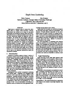
(b) Penalty curvature for Teddy
Fig. 1. Error and quadratic penalty functions constructed for one pixel in right view (view 6), and curvature of penalty functions for entire right view in Teddy.
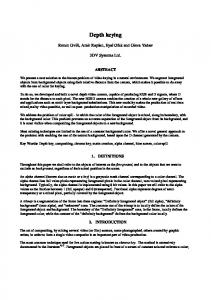
pixel values between left pixel Il (m, n), and incorrectly mapped right pixel Ir (m, n − (Dl (m, n) + e) ∗ γ) due to error e. We write: El (e; m, n) = |Il (m, n) − Ir (m, n − (Dl (m, n) + e) ∗ γ) | (2) Error function Er (e; m, n) for the right depth map can be derived similarly. As an example, the blue curve in Fig. 1(a) is the resulting Er (e; m, n) for the right view (view 6) of multiview sequence Teddy [10]. One can see that, in general, as the depth value deviates from the ground truth disparity value Dr (m, n) (red circle), the error increases. For mathematical convenience ( so that the to-be-discussed optimization can be formulated as an unconstrained quadratic program), we fit a per-pixel quadratic penalty function gi (si ) to the error function and use gi (si ) instead: gi (si ) = (1/2)ai s2i + bi si + ci
(3)
where si is the disparity value corresponding to pixel location i, and ai , bi and ci are the quadratic function parameters. The procedure we use to fit gi (si ) to the error function is as follows. Given threshold ρ, we first seek the nearest disparity Dl (m, n) − e value below ground truth Dl (m, n) that results in error El (−e; m, n) exceeding ρ + El (0; m, n). Using only two data points at Dl (m, n) − e and Dl (m, n), and assuming gi (si ) has minimum at ground truth depth value Dl (m, n), we can construct one quadratic function. Similar procedure is applied to construct another penalty function using two data points at Dl (m, n)+e and Dl (m, n) instead. The sharper of the two constructed functions (larger a) is the chosen penalty function for this pixel. Continuing with our earlier example, we see in Fig. 1(a) that two quadratic functions (in dashed lines) with minimum at ground truth depth value are constructed. The narrower of the two is chosen as the penalty function. In Fig. 1(b), the per-pixel curvature (parameter a) of the penalty functions of the right depth depth of Teddy is shown. We can clearly see that larger curvatures (larger penalties) occur at object boundaries, agreeing with our intuition that a synthesized view is more sensitive to depth pixels at object boundaries. 4. PROBLEM FORMULATION Given the defined per-pixel penalty functions, we now formulate our depth signal sparsification problem TDS—trading off representation sparsity in the transform domain with synthesized view distortion— as iterative unconstrained quadratic programs. 4.1. Defining Objective Function Let s be a depth signal in the pixel domain, where si is the depth value of the i-th pixel. Let Φ be a chosen orthogonal transform.
2011 18th IEEE International Conference on Image Processing
Hence α = Φs is the transform coefficient vector. Since only nonzero quantized transform coefficients are coded, in general the fewer the number of non-zero entries in α, the better the compression performance. The number of non-zero entries in α is equivalent to the l0 -norm kαkl0 of α: kαkl0 = |{i|αi > 0}|
2. Find optimal αo to (7) for weighted l2 -norm minimization with penalties by solving (10). 3. Set each weight wi to (|αoi |2 + �2 )−
(4)
Using the per-pixel penalty functions gi (si )’s we defined (in the pixel domain) in the previous section, we can now write our objective function for TDS as a sum of l0 -norm and weighted penalties of coefficient vector α (in the transform domain): X min kαkl0 + λ gi (φ−1 (5) i α) α
1. Initialize weights wi = 1/(|αti | + �)2 , where αti is the i-th transform coefficient of the ground truth depth signal st .
�
4−2τ 2
αo
2−τ 2
if | Qii | ≥ 0.5, and
otherwise.
4. Repeat Step 2 to 3 until convergence in quantized coefficients α ˆ oi ’s. Fig. 2. Iterative algorithm to solve weighted l2 -norm minimization with penalty functions gi (si )’s.
i
φ−1 i
where is the i-th row of the inverse transform Φ−1 , and λ is a weight parameter to control the relative importance of representation sparsity and synthesized view distortion of the sought solution. (5) is an unconstrained optimization problem where the optimization variables are transform coefficients αi ’s. Because of the combinatorial nature of l0 -norm kαkl0 in (5), finding the optimal solution to (5) is non-convex and NP-hard in general. We hence next propose alternative functional to serve as surrogate to the original objective (5) that can be more efficiently solved. 4.2. Weighted l2 -norm Surrogate Instead of minimizing l0 -norm kαkl0 directly, numerous previous approaches seek the minimum l1 -norm solution instead [11]. More generally, the weighted lp -norm kαklp (w) of coefficient vector α with weight vector w is defined as: !1/p X p wi |αi | 0