Oct 12, 2018 - Abstract. The Business Process Modeling Notation (BPMN) is a language for capturing business processes. It is able to model the complex ...
IOP Conference Series: Earth and Environmental Science
PAPER • OPEN ACCESS
Transformation and Visualization of BPMN Models to Petri Nets To cite this article: Lei Li and Fei Dai 2018 IOP Conf. Ser.: Earth Environ. Sci. 186 012047
View the article online for updates and enhancements.
This content was downloaded from IP address 139.81.183.231 on 12/10/2018 at 13:32
GBEM IOP Conf. Series: Earth and Environmental Science 186 (2018) 1234567890 ‘’“” 012047
IOP Publishing doi:10.1088/1755-1315/186/5/012047
Transformation and Visualization of BPMN Models to Petri Nets Lei Li1, Fei Dai2* 1
School of Information Science & Engineering, Yunnan University, Kunming, 650091, China 2
National Pilot School of Software, Yunnan University, Kunming, 650091, China
Abstract. The Business Process Modeling Notation (BPMN) is a language for capturing business processes. It is able to model the complex concepts of systems such as: choice, parallel, and synchronization. However it suffers from the lack of an unambiguous definition, so we may produces models with semantic errors. On the other hand, Petri nets are a formal tool with solid mathematical principles [4]. Moreover, it offers a number of analytical techniques. So Petri nets and BPMN have complementary abilities: BPMN can handle the modeling and Petri nets can handle the analysis. In this paper, we propose an approach for transforming BPMN models to Petri nets models, then assign coordinates of Petri nets elements and control the path of every arc. Finally, we get a valid and neat Petri net model which is both convenient and practical for human analysts and other Petri nets analysis techniques.
1. Introduction The Business Process Modeling Notation (BPMN) [1] is a language for capturing business processes. It is able to model the complex concepts of systems such as: choice, parallel, and synchronization. It combines elements from many notations for business process modeling, including Activity Diagrams component of the Unified Modeling Notation (UML) [2], the XML Process Definition Language (XPDL) and so on. But BPMN suffers from the lack of an unambiguous definition, so we may produces models with semantic errors. Petri nets are a formal tool with solid mathematical principles [3]. Moreover, it offers a number of analytical techniques. So Petri nets and BPMN have complementary abilities: BPMN can handle the modeling and Petri nets can handle the analysis. Analyses of BPMN models capturing critical applications can be helpful to ensure the absence of errors and the correctness. There are many previous works focusing on the transformation of BPMN models to Petri nets models. In [4], the authors used the meta-modelling and model-transforming to generate Petri nets models for BPMN using AToM3 graph tool. In [5], the authors map the BPMN models to Kripke structure and check the validity of major properties. In this paper, we propose an approach for transforming BPMN models to Petri nets models, then assign coordinates of Petri nets elements and control the path of every arc. Finally, we get a valid and neat Petri net model which is both convenient and practical for human analysts and other Petri nets analysis techniques.
Content from this work may be used under the terms of the Creative Commons Attribution 3.0 licence. Any further distribution of this work must maintain attribution to the author(s) and the title of the work, journal citation and DOI. Published under licence by IOP Publishing Ltd 1
GBEM IOP Conf. Series: Earth and Environmental Science 186 (2018) 1234567890 ‘’“” 012047
IOP Publishing doi:10.1088/1755-1315/186/5/012047
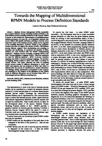
2. Subset of BPMN This paper reports experiences in defining a mapping between a subset of BPMN and Petri nets. The subset of BPMN mainly consists of elements for control-flow perspective, it is illustrated in Figure 1(Icons for BPMN elements are collected from Yaoqiang BPMN Editor [6], it is a graphical editor for business process diagrams, compliant with OMG specifications). Other non-functional features such as artifacts, groups and associations will be dealt with in future work.
Figure 1. The subset of BPMN to be mapped 3. Mapping For each element in the subset that we proposed, we define mapping rules in Table 1(Icons for Petri nets are gathered from Platform Independent Petri net Editor [7]).The mapping rules are atomic, so they are applicable for an arbitrary combination of elements in the subset. Table 1. Mapping rules for BPMN element BPMN Petri net element Rule description element Start Event in BPMN is mapped into a Petri net element combination including a place, an arc and a transition. End Event in BPMN is mapped into a Petri net element combination including a transition, an arc and a place.
transition
place
Intermediate Throw Event, Choreography Task and Parallel Gateway in BPMN are mapped into a transition.
Exclusive Gateway and Inclusive Gateway in BPMN are mapped into a place.
2
GBEM IOP Conf. Series: Earth and Environmental Science 186 (2018) 1234567890 ‘’“” 012047
IOP Publishing doi:10.1088/1755-1315/186/5/012047
In a valid Petri net, no arc may connect two places or two transitions, so the mapping rule for sequence flow is divided into four conditions shown in the left column. 4. Preprocessing Before mapping, we should preprocess the input BPMN model. The preprocessing meets the need for semantic equivalence and is without loss of generality. BPMN standards allow for graphs which are unconnected, having no start or end events and so on. Such BPMN models are not applicable for mapping. Therefore we need to transform BPMN models into well-form ones according to rules presented in Table 2. Table 2. Rules for transforming BPMN models into well-formed ones Before After No. Rule description transforming transforming 1
Insert a parallel gateway for a start event which has an outdegree of more than one.
2
Insert an exclusive gateway for an end event which has an indegree of more than one.
3
Insert a parallel gateway for an intermediate throw event which has an outdegree of more than one.
4
Insert an exclusive gateway for an intermediate throw event which has an indegree of more than one.
5
6
7
8
Insert a parallel gateway after a parallel gateway which has an indegree of more than one and outdegree of more than one. Then apply the rule No.6 below. If a parallel gateway connects a parallel gateway, we insert a choreography task between them. The input may be the result of the rule No.5 above or exists independently. Insert an exclusive (inclusive) gateway after an exclusive (inclusive) gateway which has an indegree of more than one and outdegree of more than one. Then apply the rule No.8 below. If an exclusive (inclusive) gateway connects an exclusive (inclusive) gateway, we insert a choreography task between them. The input may be the result of the rule No.7 above or exists independently.
3
GBEM IOP Conf. Series: Earth and Environmental Science 186 (2018) 1234567890 ‘’“” 012047
IOP Publishing doi:10.1088/1755-1315/186/5/012047
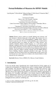
5. Layout of Petri net elements Preprocessing transforms BPMN models into well-formed ones, and then we map these well-formed BPMN models into Petri net elements. Some analysis of Petri net can work well without displaying elements in the user interface such as the reachability problem for Petri nets which is EXPSPACEhard, it gives a Petri net N and a marking M, then walk the reachability graph until either we reach the requested marking or we know it cannot be found in further attempts [8]. However in many cases, it’s necessary for researchers to analyse manually the semantics of Petri nets. To bolster human analysts, we should assign coordinates of Petri net elements. Otherwise, elements will overlap together at the top-left corner of the Petri net editor such as PIPE. A simple layout scheme is to use coordinates of the source BPMN model. However, we define a new layout scheme instead of adopting it for two reasons. Firstly, a standardised layout of a Petri net is propitious to visual analysis. We can easily seek out differences among Petri nets by checking elements at the same position. Coordinates assigned manually cannot offer such a convenience. Secondly, some Petri net elements have features because of the layout rules. For example, elements which have an indegree of zero will always locate on the left side of the Petri net editor. We use a modified version of the topological sort algorithm [9] to determine the order for assigning coordinates of Petri net elements. A topological sort is a linear ordering of vertices in a directed graph. One of the topological ordering algorithms works as following steps. Firstly, find all nodes that have no incoming edges and add them into a set S. While S is non-empty, we continuously remove a node n from S, remove edges come from the node n and insert nodes which have no incoming edge into S. Until the loop ends, if the graph still contains edges, the graph has at least one cycle. Otherwise, we acquire a topologically sorted order successfully. Since a Petri net can be cyclic, we require a few modifications of the topological ordering algorithm. We show the procedures of our algorithm in Figure 2.
4
GBEM IOP Conf. Series: Earth and Environmental Science 186 (2018) 1234567890 ‘’“” 012047
IOP Publishing doi:10.1088/1755-1315/186/5/012047
Start We have a initial set S containing all elements, add these elements into a queue Q one by one.
Is Q empty?
Y
N
Remove the first element FE in Q.
Y
Is FE processed? N
Insert FE at the tail of Q. Means that we will process it later.
Assume that the previous element PE of FE locates at point P(X=0,Y=0).
Does FE has a previous element?
N
Y
Y
Does FE has unprocessed previous elements which not lead to a cycle? N
Now all the previous elements except those lead to a cycle have their coordinates assigned. Then: P.X=max(xi) and P.Y=min(yi).
We define a variable D controlling the distance between two elements in the horizontal and vertical direction. Then coordinates of current element FE will be assigned to (P.X+D, P.Y+k*D).While k is the smallest integer in condition of that no element has occupied the point (P.X+D, P.Y+k*D).Finally, we add an attribute to FE to indicate that it has been processed. End
Figure 2. The flowchart for assigning coordinates of Petri net elements 6. Controlling the path of an arc In a Petri net instance, if we only define the start point and the end point of an arc, there will be a straight line between two points. In a complex Petri net, these straight lines may overlap with other elements and arcs. It’s a confusing situation which is bad for human analysts. We use a modified version of A* search algorithm to control paths of arcs. A* (pronounced as "A star") is a computer algorithm that is widely used in path finding. Specifically, A* finds a path which minimizes f(n)=g(n)+h(n), g(n) is the total cost from the start node to n, and h(n) is a heuristic which values the cost from n to the goal. Figure 3 shows details, modifications are underlined. We introduce some definitions of this flowchart: S(x, y) stands for the start point of an arc; E(x, y) stands for the end point of the arc. A variable D stands for the minimal distance between two points in the horizontal and vertical direction. A variable RA stands for the number of the right angles in the path. When RA