Transformation of Measurements for Using External Network Equivalents in State Estimation M. Vardikar, Student Member, IEEE S. Chakrabarti, Senior Member, IEEE Department of Electrical Engineering Indian Institute of Technology Kanpur, India
[email protected],
[email protected] Abstract—Network reduction techniques are attractive options for the analysis of large, complex power systems. In the process of network reduction, the original measurements usually get transformed along with the network parameters. It is therefore essential to take into account these transformations in applications such as state estimation. This paper presents a methodology for determining the relation between the measurements in the reduced system and the measurements in the original system. State estimation can then be carried out with the help of the transformed measurements. The developed method is applied on the IEEE 14 bus and IEEE 118 bus test systems. Index Terms—Network reduction, power system measurements, state estimation.
I.
INTRODUCTION
Simulation and analysis of a large interconnected power system in real-time is a challenging task even with the help of the state-of-the-art high speed computing facilities. The use of network equivalents is therefore an attractive option for various tasks such as power flow, security analysis, stability analysis, and state estimation for large systems. For various real time monitoring and control applications, the state estimation application needs to be fast and reliable while maintaining the required accuracy. Such criteria for state estimation demand improved system modeling and computation methods. In general, a utility, referred to as the internal system in this paper, carries out its state estimation considering an adequate model of the system external to itself [1]. In order to determine the operating condition of the internal system, the effect of the external system can be considered in three ways: in the unreduced form, the reduced form, or a combination of the two [1]. The unreduced form provides the most accurate results, but the computational time is the highest among the three approaches. The reduced form of the external network is obtained by network reduction procedures such as Ward equivalent and REI net equivalent [2]-[4]. The basic ward equivalent of a network is obtained by converting power injections at selected buses into constant current injections or
978-1-4799-1303-9/13/$31.00 ©2013 IEEE
E. Kyriakides, Senior Member, IEEE Department of Electrical and Computer Engineering KIOS Research Center for Intelligent Systems and Networks University of Cyprus Nicosia, Cyprus
[email protected]
admittances followed by Gaussian elimination. The REI (Radial Equivalent Independent) equivalent is formed by aggregating a selected group of nodes on a fictitious REI node [5]. The reduced form of the network is required to reflect the full system operating conditions, while simplifying the analysis at the same time. Methodologies exist in the literature to identify the most sensitive measurements from the external areas, which, when retained in the reduced network, accurately reflect the behavior of the original unreduced network [5]. Ref. [6] suggests use of ANN for obtaining equivalent network of external system. It uses power flows in tie-lines and complex voltages at boundary buses for determining equivalent. But providing extensive cases for training of ANN is most difficult part as noted in [6]. While in [7], the authors have investigated effect of different levels of data exchange from the external to the internal area for state estimation. The reduction methods such as ward, REI equivalent provide reduced form of network, however for state estimation purposes, one has to work with the measurements, both from the internal and the external areas. To the authors’ knowledge, the issue that has not been properly addressed in the literature is that the external measurements get transformed because of the network reduction process, and hence cannot be used in their original form in the reduced network. This paper presents a way to trace the changes in the measurements as a result of network reduction. After considering the transformations in the measurements, they can be used for carrying out the state estimation for the reduced system. The organization of paper is as follows. Section I introduces the paper. Section II of this paper provides an overview of the network reduction technique using Gaussian elimination. Section III describes the sensitivity analysis method adopted from [5] for the selection of the significant external area measurements. Section IV describes the transformation of the measurements from the full system to the reduced equivalent at a given operating condition. Section V discusses the simulation results for the test systems, and Section VI concludes the paper.
II.
NETWORK REDUCTION
The basic objective in the network reduction techniques is to reduce the problem size and the computational requirements, while maintaining the required accuracy. The Gaussian elimination (also known as the method of successive elimination) is one of the basic network reduction techniques, and it has been well explained and utilized in the literature [8, 9]. It is an important component of many reduction techniques such as Dimo’s or REI reduction [10]. In this work, the Gaussian elimination technique is used to obtain the reduced equivalents for the external networks. Let a power system be described by the following set of nodal equations.
Ybus v = i i
(1)
where Ybus is the n × n bus admittance matrix, v is the n × 1 vector of complex voltages at all nodes, and ii is the n × 1 vector of complex currents injected at all nodes. After elimination of the mth node, Ybus is modified as [6],
Y jk(1) = Y jk −
Y jm Ymk Ymm
, ∀j , k = 1,..., n; j ≠ m, k ≠ m
The current vector ii is also modified as, Y jm I (j1) = I j − Im , ∀j = 1,..., n; j ≠ m. Ymm
(2)
(3)
SENSITIVITY ANALYSIS
The changes in the external area generations and loads affect the internal area through changes in the tie-line power flows. Hence, those external area measurements, which affect the tieline power flows significantly, will be selected as the effective measurements, while others will be kept at their base case values. The sensitivity analysis for the selection of measurements from the external area is as follows and is based on the techniques discussed in [5]. The measurement equations can be partitioned as per the division of the buses, viz., internal, boundary and external buses. For finding out the significant measurements in the external system, the tie-line flows are taken as the states of the system along with the bus voltage magnitudes and angles by adding a zero impedance line for each tie line [5]. The weighted least squares (WLS) estimates for the states are then given by,
S IB S IE ⎤ ⎥ ⎡ Δz I ⎤ S BB S BE ⎥ ⎢ ⎥ Δz B ⎥ S EB S EE ⎥ ⎢ ⎥ ⎢Δz E ⎥⎦ S FB S FE ⎦⎥ ⎣
(4)
Here Δx F is the vector of tie-line flow mismatches. The subscripts I, B, and E represent internal, boundary and external quantities. The vector Δz consists of mismatches in the measurements. The sensitivities of the tie line flows with respect to the external measurements can be found from submatrix SFE. These sensitivities are used to select the most significant measurements from the external area. While performing the state estimation, these measurements need to be updated frequently, keeping the remaining measurements at their base case values under small changes in the operating conditions. It is to be noted that throughout this paper, the convention for four frequently used subscripts is as follows. The subscripts ‘i’ and ‘l’ denote nodal injection and line flow related quantities, respectively. The subscripts ‘o’ and ‘r’ denote original and reduced system related quantities, respectively. IV.
The elements of the voltage vector corresponding to the retained nodes remain unchanged even after the above modifications. Every step of the Gaussian elimination yields an equivalent circuit of the network at the base case. If the network is reduced to r nodes, a new bus admittance matrix of dimension r × r, and a new current injection vector of dimension r × 1 are obtained. This reduced network carries full information of the original power system at the base case. III.
⎡Δx I ⎤ ⎡S II ⎢ ⎥ ⎢ ⎢Δx B ⎥ = ⎢S BI ⎢Δx E ⎥ ⎢S EI ⎢ ⎥ ⎢ ⎣⎢Δx F ⎦⎥ ⎣⎢S FI
TRANSFORMATION OF MEASUREMENTS
Transformation of measurements in the context of this paper refers to finding the power injection and flow measurements in the reduced system, given the power injection and flows in the original system. For a network, the nodal current injections can be expressed in terms of the branch flows and the currents through the shunt branches connected to the nodes as follows.
i i = Ai l + Bv
(5)
i l = Hv
(6)
where A is the network connectivity matrix, i l is the vector of the complex line currents for all lines, B is a diagonal matrix consisting of the admittances at each node connected to the ground, and H is the matrix formed by using the line admittances such that (6) holds true.
Ybus v = i i = Ai l + Bv
(7)
Let the original network consist of n nodes and l lines. This network is reduced to have nr nodes and lr lines. The transformations in the measurements due to network reduction are explained in the following two sub-sections. A. Injection Measurements The injection currents for the reduced system are,
i ir = Ybusr v = A r i lr + B r v
(8)
For the reduced system, the vector of complex line currents is formed as follows. The current through a line between buses i and j, with line admittance Yij , is given by,
Iij = Yij ( Vi − Vj )
(9)
Considering all the line currents, the above relation can be written in matrix form as,
i lr = H r v r
Or, −1 s ∗ir = Vir ( A r H'+B r )Ybuso Vio-1s ∗io
In terms of real and reactive power, (18) can be written as,
(10)
Here ilr is the vector of complex currents through the lines of the reduced network, Hr is the matrix of the corresponding line admittances, and vr is the vector of voltages at the retained nodes. Adding zero elements corresponding to the eliminated nodes in the matrix Hr, and replacing vr by v, the vector of original node voltages, the following is obtained.
(18)
p ir − jq ir = Cinj (p io − jq io )
(19)
where the transformation matrix Cinj is given by, -1 C inj = Vir ( A r H '+B r )Ybuso Vio−1
(20)
In (21) the elements of the injection measurement
(11)
transformation matrix C inj depend on both original and reduced network parameters, the network configuration, and the base case complex voltages at all nodes.
Using (11) in (8) and expressing v in terms of the original bus admittance matrix Ybus and the node injection vector i i according to (1),
B. Flow Measurements The complex current flows in the reduced system are given in (11). Rewriting (7) for the original system,
i lr = H' v where H ' is a matrix of dimension lr × n.
−1 i ir = A r H' v + B r v = ( A r H '+B r )Ybuso i io
Equation (12) expresses the current injections at nodes in the reduced network in terms of the current injections in the original network. Since most of the measurements are in the form of power injections or power flows, such transformations need to be established for power measurements as well. The conjugate of the complex power injection at a node is given by, *
*
S =V I
(13)
where V and I are the nodal complex voltage and current injections, respectively. Let four diagonal matrices Vio (n × n), Vlo (l × l), Vir (nr × nr), and Vlr (lr × lr) be now defined for the original and the reduced network, respectively, with the conjugate of the node voltages as the diagonal elements, i.e., Vio (k , k ) = Vk∗ , and so on. Then,
Vio i io = s ∗io = p io − jq io
(14)
Vlo i lo = s ∗lo = p lo − jq lo
(15)
Vir i ir = s ∗ir = p ir − jq ir
(16)
Vlr i lr = s ∗lr = p lr − jq lr
(17)
where s*’s are the vectors of complex conjugate power injections at nodes or complex conjugate power flows through lines (denoted by subscripts ‘i’ and ‘l’, respectively). The vectors p’s and q’s are real and imaginary components of the corresponding complex power. Multiplying (12) by Vir (defined earlier) on both sides, and inserting Vio−1Vio , a unity matrix of dimension n × n, −1 Vir i ir = Vir ( A r H '+B r )Ybuso Vio-1Vio i io
Ybuso v = i io = A o i lo + B o v
(12)
(21)
As the voltage vector v remains unchanged during the reduction process, the expression for v can be obtained in terms of the original system quantities, as shown below −1 −1 −1 v = Ybuso A o i lo + Ybuso B o Ybuso i io
(22)
Using (23) in (11), −1 −1 −1 i lr = H' (Ybuso A o i lo + Ybuso B o Ybuso i io )
(23)
Equation (23) expresses the current flows in the reduced network in terms of the current injections and current flows in the original network. The expression in terms of power injections and flows can be obtained as follows. Multiplying (23) throughout by Vlr (defined earlier), −1 −1 −1 Vlr i lr = Vlr H' Ybuso A o i lo + Vlr H ' Ybuso B o Ybuso i io
(24)
Inserting Vlo−1Vlo and Vio−1Vio , the unity matrices of dimension lr × lr and nr × nr , respectively, and rearranging terms, −1 Vlr i lr = (Vlr H' Ybuso A o Vlo−1 )Vlo i lo + −1 −1 (Vlr H ' Ybuso B o Ybuso Vio−1 )Vio i io
(25)
Using (14)-(17), (25) can be written as,
s ∗lr = C flow s ∗lo + C iflow s ∗io l Or,
p lr − jq lr = C flow (p lo − jq lo ) + Ciflow (p io − jq io ) l
(26)
where the transformation matrices are given by, −1 C flow = Vlr H' Ybuso A o Vlo−1 l
(27)
−1 −1 = Vlr H' (Ybuso B o Ybuso Vio−1 ) and Cflow i
(28)
The transformation matrices in (27) and (28) relate the power flow measurements in the reduced network to the power injection and flow measurements in the original network. V.
CASE STUDIES
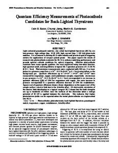
The proposed methodologies are applied on the IEEE-14 bus and the IEEE -118 bus test systems [11]. The test systems are partitioned into internal and external areas to demonstrate the methodologies. Fig. 1 shows the partitioning of the 14-bus system and Table I shows the buses in the internal and the external area.
TABLE II.
SIGNIFICANT EXTERNAL AREA MEASUREMENTS FOR THE IEEE 14-BUS SYSTEM AT THE BASE CASE
Type of Measurement Power injections Power flows
Measurements location, Bus / Line 7, 9 6-11, 7-9, 9-11, 10-11
In the second step, the loads in the external area are varied within ±30% of their respective base case values. This change in load is compensated by all generators and in proportion to their respective base case generation share. For the purpose of state estimation, the measurements are generated in this work by adding random noise to the power flow results at the given operating condition. In order to demonstrate the proposed methods, two configurations of the reduced network are used. Case 1: Only generator buses are retained from the external area.
TABLE I.
PARTITIONING OF THE IEEE 14-BUS SYSTEM
Internal System buses
External System buses
1, 2, 3, 4, 5
6, 7, 8, 9, 10, 11, 12, 13, 14
The average absolute per unit errors in the estimated voltage magnitudes and average absolute error in degrees for the voltage angles are used as the criteria for evaluating the performance of the state estimator. The state estimation results for the above two reduced network configurations are shown in Table III. It can be seen that the errors associated with the reduced system are small and comparable with those for the original unreduced system. This shows the effectiveness of the proposed network reduction and measurement transformation methodologies.
Bus 14
Bus 12 Bus 13
External area
Bus 10
TABLE III. COMPARISON OF THE STATE ESTIMATION RESULTS FOR THE ORIGINAL AND REDUCED NETWORK FOR THE 14-BUS TEST SYSTEM
Bus 9 Bus 7 Bus 11
Bus 6
Bus 8 Bus 4 Bus 5 s la c k
Bus 3
Bus 1
Case 2: All buses are eliminated from the external area.
Internal area
Bus 2
Figure 1. Partitioned 14-bus system.
In the first step, the sensitivity analysis is carried out and the significant measurements are selected based on the elements of the sensitivity matrix, S, as explained in Section III. The threshold used in this work to determine the sensitive elements is 0.18. The selection of this threshold is based on the accuracy requirements and the amount of data to be communicated from the external to the internal area. All the external area measurements with sensitivity above the cutoff are selected and communicated from the external area to the internal area for the state estimation of the reduced system. The results of the sensitivity analysis indicated the most significant external measurements as shown in Table II. Only these measurements from the external area are updated to be used in the state estimation. The other external area measurements are kept at their respective base case values.
Original system Average Average Loading absolute absolute Reduced level (% of error in error in network base case voltage voltage value) angle magnitude (degree) (pu) 100 0.0008 0.0073 Case 1 130 0.0047 0.0439 70 0.0049 0.0384 100 0.0009 0.0076 Case 2 130 0.0046 0.0358 70 0.0053 0.0480
Reduced system Average Average absolute absolute error in error in voltage voltage angle magnitude (degree) (pu) 0.0023 0.0637 0.0052 0.3612 0.0103 0.1449 0.0038 0.0561 0.0171 0.6326 0.0197 0.3291
The second system considered for the evaluation of the proposed methodologies is the IEEE-118 bus test system. The system is divided into two parts: the internal and the external system, as shown in Table IV. TABLE IV.
PARTITIONING OF THE IEEE 118-BUS SYSTEM
Internal System buses 24,45-77,116,118
External System buses 1-23,25-44,78-115,117
Similar steps, as described for the 14-bus system, were carried out for the state estimation of the 118-bus system. For the partitioned 118-bus system, the sensitivity analysis indicated the most significant measurements from the external area as shown in Table V.
TABLE V.
SIGNIFICANT EXTERNAL AREA MEASUREMENTS FOR THE 118-BUS SYSTEM AT THE BASE CASE
Type of Measurement Power injections Power flows
Measurements location, Bus / Line 23,32,38,40,42,43,44,78,79,80,81,82,83,96,97,99. 23-32,38-37,43-44,78-79,79-80,80-81,82-83,8384,83-85,82-96,80-99,95-96,96-97,99-100.
Similar to the case for the 14-bus system, the loads in the external area for the 118-bus system are varied within ±30% from their respective base case values, and the generations are adjusted accordingly proportional to their participation in the base case. The state estimation results for the 118-bus system are given in Table VI. The measurement transformation methodology applied on the reduced network shows promising results of state estimation in terms of accuracy.
VI.
Representing the external area networks by reduced network equivalents is a widely used practice in power system state estimation for minimizing the computational burden and eliminating the need for communicating a large amount of measurement data in real-time. This paper proposes a methodology to trace the transformations in the measurements that need to be considered as a result of the network reduction process. Using these transformations, state estimation can be effectively carried out for the internal area, considering the available measurements from the internal as well as the external areas. The proposed methodologies are successfully tested on the partitioned IEEE 14-bus and IEEE 118-bus test systems. REFERENCES [1]
TABLE VI. COMPARISON OF THE STATE ESTIMATION RESULTS FOR THE ORIGINAL AND REDUCED NETWORK FOR THE 118-BUS TEST SYSTEM
Loading Reduced level (% of network base case value)
Case 1 Case 2
100 130 70 100 130 70
Original system Average Average absolute absolute error in error in voltage voltage angle magnitude (degree) (pu) 0.0016 0.0170 0.0158 0.0894 0.0029 0.0214 0.0013 0.0073 0.0143 0.0745 0.0041 0.0697
Reduced system Average Average absolute absolute error in error in voltage voltage angle magnitude (degree) (pu) 0.0235 0.1134 0.0449 0.6891 0.0082 0.3713 0.0289 0.1261 0.0491 0.7290 0.0167 0.4419
It is observed that the reduced system, with only sensitive measurements supplied from the external area, also provides reasonably accurate estimates of the states. As the state estimation problem size becomes smaller with the reduction of the network size, the computational time required for the reduced system is much less than the original unreduced system. The methodology was implemented on a desktop computer (2.19 GHz, 2GB RAM) using MATLAB 7.12 for computation. Computational time comparison for state estimation for the original and the reduced system is provided in Table VII below. TABLE VII. COMPUTATIONAL TIME REQUIRED FOR STATE ESTIMATION FOR THE ORIGINAL AND REDUCED NETWORK Test System 14-bus Test System 118-bus Test System
Average time for solution (seconds) Original system Reduced system 0.37 0.028 21.7 1.30
CONCLUSION
A. Monticelli, State Estimation in Electric Power Systems: A Generalized Approach, Kluwer, 1999, pp. 5-6. [2] J. B. Ward, “Equivalent circuits for power flow studies,” AIEE Trans. Power App. Syst., vol. 68, pp. 373–382, 1949. [3] A. Monticelli and S. Deckmann and A. Garcia and B. Stott, “Real-time external equivalents for static security analysis”, IEEE Trans. Power App. Syst., PAS-98:498-508, 1979. [4] T. E. Dy Liacco, K.A. Ramarao and S. C. Savulescu, “An on-line topological equivalent of a power system,” IEEE PAS Summer Meeting, 1977. [5] F. F. Wu and A. Monticelli, “A critical review on external network modeling for on-line security analysis,” International Journal of Electrical Power and Energy Systems, pp. 222–235, Oct. 1983 [6] H. Kim and A. Abur, "Enhancement of External System Modeling for State Estimation", IEEE Trans, on Power Systems, Vol. 11, No. 3, pp. 1380-1386, Aug. 1996. [7] A. Larsson, A. Germond, and B. Zhang, “Application of neural networks to the identification of steady state equivalents of external power systems,” IEEE International Conference on Power System Technology, Chongqing, China, pp. 1-6, Oct. 2006. [8] K.K.Y Poon, R.Emami, A. Bose, and A. Abur, “External data exchange issues for state estimation in power systems,” IEEE Transactions on Power Systems, vol. 27, no.2, pp.849-856, May 2012. [9] J. J. Grainger and W. D. Stevenson, Power System Analysis, McGrawHill, 1994, pp. 263-274. [10] W. F. Tinney and W. S. Meyer, “Solution of large sparse systems by ordered triangular factorization,” IEEE Trans. Automatic Control, vol. 18, no. 4, pp. 333-346, 1973 [11] S. C. Savulescu, Real-Time Stability Assessment in Modern Power System Control Centers, John Wiley & Sons, 2009, pp. 307. [12] IEEE test system data available at www.ee.washington.edu/research/pstca/