e is the elapsed time since last transition, and s the ... The next state depends on the elapsed time in ..... The simulation has been performed using the Python-.
Transformation of VHDL Descriptions into DEVS Models for Fault Modeling∗ Laurent Capocchi, Fabrice Bernardi, Dominique Federici and Paul Bisgambiglia University of Corsica, SPE Laboratory, UMR CNRS 6134 20250 Corte, France {capocchi, bernardi, federici, bisgambi}@univ-corse.fr Abstract – We propose in this article an approach for the transformation of VHDL descriptions into DEVS models for an easy and fast fault simulation. VHDL allows description of the structure of a design, that is how it is decomposed into sub-designs, and how those designs are interconnected. The specification of the function of designs are performed using familiar programming language forms. One of the main problems is that today tools are unable to quickly and easily create and simulate fault models directly from the VHDL descriptions. A way to solve this problem is to encapsulate these descriptions in easily simulable and evolutive models. We propose to use the DEVS formalism to achieve this encapsulation. Keywords: VHDL descriptions, DEVS formalism, modeling, simulation, fault.
1
Introduction
Tests are a very important part in the digital systems design process. Fault modeling is one part of the tests that can be performed. We call ”fault” the detection of an incorrect step, process or data definition in the design process [1, 2]. A fault model identifies targets for testing and makes analysis possible. VHDL is an hardware description language widely used in the digital systems industry [3]. It allows description of the structure of a design, that is how it is decomposed into sub-designs, and how those designs are interconnected. The specification of the function of designs are performed using familiar programming language forms. One of the main problems is that today tools are unable to quickly and easily create and simulate fault models directly from the VHDL descriptions. A way to solve this problem is to encapsulate these descriptions in easily simulable and evolutive models. We propose to use the DEVS formalism to achieve this encapsulation. Introduced by B.P. Zeigler in the early 70’s, DEVS is a set-theoretic formalism that provides a mean of modeling discrete event systems in a hierarchical and ∗ 0-7803-7952-7/03/$17.00
c 2003 IEEE.
modular way [4]. Using this formalism, we can perform more easy modeling in decomposing a large system into smaller component models with coupling specifications between them. DEVS defines two kinds of models: atomic models and coupled models. An atomic model is a basic model with specifications for the dynamics of the model. It describes the behavior of a component, which is indivisible, in a timed state transition level. Coupled models tell how to couple several component models together to form a new model. This kind of model can be employed as a component in a larger coupled model, thus giving rise to the construction of complex models in a hierarchical fashion. Our choice for DEVS has been motivated by three main points. First, digital systems can be represented by discrete event systems, and DEVS is the leading formalism in discrete event modeling and simulation. Second, a great advantage of DEVS is that it separates the modeling and simulation parts in a very efficient way, since the simulator is built directly from the model. Last, DEVS uses a modular approach that allows an easy introduction of the fault models [5]. In a first section, we describe the VHDL language, and the DEVS formalism in a second one. The main part of this article is the third section. We propose a modeling approach for the VHDL descriptions based on the definition of four basic DEVS atomic models. Finally, we propose an example of modeling and simulation and we conclude this article.
2
VHDL Fault Modeling
VHDL allows to describe a digital structure following two types of descriptions: the structural description and the behavioural description. In the structural description, the design is described as a module with inputs and/or outputs. The electrical values on the outputs are some function of the values on the input. One way to represent the function of the module is to describe how it is composed of sub-models. However, in many cases, it is not appropriate to describe a module structurally. In the behavioural description, the function is described without reference to the actual internal structure of the
module. We can find two forms for the behavioural description: the data flow form or the algorithmic form. In this paper, we study only this last form, since it has been demonstrated that any combinatory structure can be described using sequential statements [6]. A digital system in VHDL consists of a design entity containing other entities that are then considered components of the top-level entity. Each entity is modeled by an entity declaration and an architecture body. One can consider the entity declaration as the interface to the outside world that defines the input and output signals, while the architecture body contains the description of the entity and is composed of interconnected entities, processes and components, all operating concurrently. entity NAME_OF_ENTITY is generic (generic_declarations); port (signal_names: mode type; signal_names: mode type; signal_names: mode type); : end [NAME_OF_ENTITY]; The architecture body specifies how the circuit operates and how it is implemented. As discussed earlier, an entity or circuit can be specified in a variety of ways, such as behavioral, structural (interconnected components), or a combination of the above. architecture arch_name of NAME_OF_ENTITY is -- components declarations -- signal declarations -- constant declarations -- function declarations -- procedure declarations -- type declarations begin -- Statements end architecture_name; The statements in the body of the architecture make use of logic operators. Logic operators that are allowed are: and, or, nand, nor, xor, xnor and not. In addition, other types of operators including relational, shift, arithmetic are allowed as well. The basis for sequential modeling is the process construct. A process statement is the main construct in behavioral modeling that allows you to use sequential statements to describe the behavior of a system over time. The syntax for a process statement is: [process_label:] process [(sensitivity_list)] [process_declarations] begin list of sequential statements such as: signal assignments variable assignments case statement
exit statement if statement loop statement next statement null statement procedure call wait statement end process [process_label]; A process is declared within an architecture and is a concurrent statement. However, the statements inside a process are executed sequentially. Like other concurrent statements, a process reads and writes signals and values of the interface (input and output) ports to communicate with the rest of the architecture.
3
DEVS Formalism
DEVS formalism introduces two kind of models, atomic models from which larger ones are built, and coupled models (also called network of models) that connects those models in a hierarchical fashion [7]. Like in general systems theory, a DEVS model contains a set of states and transition functions that are triggered by the simulator. A DEVS atomic model AM is a structure : AM =< X, S, Y, δint , δext , λ, ta > where: • X: {(p, v)|(p∈ input ports, v∈ Xp)} is the set of input ports and values for the reception of external events, • Y: {(p, v)|(p∈ output ports, v∈ Yp)} is the set of output ports and values for the emission of events, • S is the set of internal sequential states, • δint : S → S is the internal transition function that will move the system to the next state after the time returned by the time advance function, • ta : S → + is the time advance function, that will give the life time of the current state (returns the time to the next internal transition), • δext : Q×X → S is the external transition function that will schedule the states changes in reaction to an input event, • λ : Q×X → S is the output function that will generate external events just before the internal transition takes places. The dynamic interpretation is the following: • Q = {(s, e)|(s ∈ S, 0 < e < ta(s)} is the total state set.
• e is the elapsed time since last transition, and s the partial set of states for the duration of ta(s) if no external event occur. • δint : the model being in a state s at ti, it will go into s’, s’ =δint (s), if no external events occurs before ti + ta(s). • δext : when an external event occurs, the model being in the state s since the elapsed time e goes in s’, s’ =δext (s,e,x). – The next state depends on the elapsed time in the present state. – At every state change, e is reset to 0. • λ : the output function is executed before an internal transition, before emitting an output event the model remains in a transient state. • A state with an infinite life time is a passive state (steady state), else, it is an active state (transient state). If the state s is passive, the model can evolve only with an input event occurrence.
4
VHDL Descriptions Transformations
Our basic approach for the transformation is to associate each VHDL instruction with a DEVS atomic model, and each process with a DEVS coupled model. We defined four basic atomic models kinds. The first one is the ”allocation model” kind that represents the VHDL allocation instructions. We can note that this model is able to handle time delayed allocations. The second is the ”junction model” kind that represents how two atomic models are linked together. The third is the “conditional model” kind that represents the classical control instructions (if, case, for,...). Finally, the last one is the ”parallel model” kind that manages the parallel execution of processes. All these basic models can be easily personalized and combined in order to create complex models.
4.1
The Allocation Model
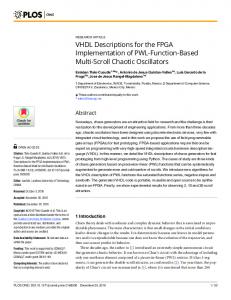
The allocation model (Figure 1) is used to describe any type of allocation that does not take into account the notion of “delay”.
In
The DEVS coupled model CM is a structure :
ALLOCATION
Out
AM
CM =< X, Y, D, {Md ∈ D}, EIC, EOC, IC >
Figure 1: The Allocation Model
where: The associate atomic model is the following: • X is he set of input ports for the reception of external events, • Y is the set of output ports for the emission of external events, • D is the set of components (coupled or basic models), • Md is the DEVS model for each
d
∈ D,
• EIC is the set of input links, that connects the inputs of the coupled model to one or more of the inputs of the components that it contains, • EOC is the set of output links, that connects the outputs of one or more of the contained components to the output of the coupled model, • IC is the set of internal links, that connects the output ports of the components to the input ports of the components in the coupled models. In a coupled model, an output port from a model Md ∈ D can be connected to the input of another Md ∈ D but cannot be connected directly to itself.
AM(alloc) =< X, S, Y, δext , δint , λ, ta > where: X = {(”In”, v)|v ∈ V } Y = {(”Out”, v)|v ∈ V } S = {”active”, ”passive”} ×
+ 0
× {allocation}
S
∅
δint (phase, σ, task) = (”passive”, ∞, ∅) δext (phase, σ, task, e, (In, message)) = (”active”, 0, allocation), if phase = ”passive” λ(phase, σ, task) = (Out, message) ta(phase, σ, task) = σ Figure 2 presents the DEVS trajectories of an allocation model. When an event occurs through the input port, the component becomes ”active” using the δext function. Then, the main task to achieve is to evaluate the assignment statement and to poke the output message using the λ function.
4.2
The Junction Model
The junction model (Figure 3) is used to describe sequential instructions like “end if, end elsif, end case”.
In
tive” using the δext function and the input port is selected. Then the λ function is actived and returns the selected input message.
message
S
t
4.3
t
The conditional model (Figure 4) occur in control structures like “if..then..else, when..else, with..select..when, case”.
active passive
passive e
inf
The Conditional Model
In
Out1 Out2 Out3 OutN
t
task
CONDITIONAL AM
allocation
Figure 4: The Conditional Model none
none Out
t
message
It is described by the following atomic model: AM(conditional) =< X, S, Y, δext , δint , λ, ta >
t
Figure 2: Allocation model trajectories In1 In2
JUNCTION
where X = {(”In”, v)|v ∈ V } Y = {(”Out0 ”, v), · · · , (”OutN ”, v)|v ∈ V } S = {”active”, ”passive”} × + 0 × {”Sw0 ”, · · · , ”SwN ”}
Out
AM InN
Figure 3: The Junction Model The associate atomic model is the following: AM(junction) =< X, S, Y, δext , δint , λ, ta > where: X = {(”In0 ”, v), · · · , (”InN ”, v)|v ∈ V } Y = {(”Out”, v)|v ∈ V } S = {”active”, ”passive”} × + 0× {”In0 ”, · · · , ”InN ”} × V δint (phase, σ, input port) = (”passive”, ∞, input port) δext (phase, σ, input port, e, (p, v)) if (phase = ”passive”) and (p ∈ {In0 , · · · , InN }) = (”active”, 0, p, v) else = (”passive”, ∞, input port) λ(phase, σ, input port) if (phase = ”active”) and (In0 , message) = (Out, In0 ) .. . if (phase = ”active”) and (InN , message) = (Out, InN ) ta(phase, σ, input port) = σ If the component is in the ”passive” phase and if an event occurs on an input port, the phase becomes ”ac-
δint (phase, σ, Sw) = (”passive”, ∞, Sw) δext (phase, σ, Sw, e, (In, message)) if (phase = ”passive”) and (Sw = ”Sw0 ”) = (”active”, 0, ”Sw0”) .. . if (phase = ”passive”) and (Sw = ”SwN ”) = (”active”, 0, ”SwN ”) = (”passive”, ∞, Sw) other λ(phase, σ, Sw) if (phase = ”active”) and (Sw = ”Sw0 ”) = (Out0 , message) .. . if (phase = ”active”) and (Sw = ”Sw0 ”) = (OutN , message) ta(phase, σ, Sw) = σ When an event occurs through the input port, the component becomes ”active” using the δext function. Then, the main task to achieve is to evaluate the conditional statement and to poke the output message into the selected port using the λ function. We can note that it exists as many output ports than values into the conditional statement.
In
m1
m2
m3
t
S
(active,0,Sw1)
(passive,inf,Sw) e
(active,0,SwN)
(active,0,Sw2)
(passive,inf,Sw)
(passive,inf,Sw)
t
inf inf
λ(phase, σ, c, status, process) if phase = ”active” = {(OutF eedback0 , msg), · · · , (OutF eedbackN , msg)} else = {(Out0 , mesg), · · · , (OutM , mesg)}
inf
t Sw
Sw1
SwN
Sw2
t Out1
ta(phase, σ, c, status, process) = σ
m1
t Out2
m2
t OutN
m3
t
Figure 5: Conditional model trajectories
4.4
The Parallel Model
The parallel model (Figure 6) is used in order to synchronize the parallel execution of the processes. It is also used in order to manage the symbolic time.
In1
In2
In3
InN
PARALLEL AM Out1
OutM OutFeedback_1
OutFeedback_N
Figure 6: The Parallel Model This model is described by the following atomic model: AM(parallel) =< X, S, Y, δext , δint , λ, ta > where X = {(”In0 ”, v), · · · , (”InN ”, v)|v ∈ V } Y = {(”OutF eedback0 ”, v), · · · , (”OutF eedbackN ”, v)| v ∈ V } ∪ {(”Out0 ”, v), · · · , (”OutM ”, v)|v ∈ V } + S = {”active”, ”passive”} × + 0 × 0 ×{”physique”, ”symbolique”} × {”P 0”, ”P 1”, ...} δint (phase, σ, c, status, process) if phase = ”active” = (”passive”, ∞, activeprocesses, ”physical”, null) else = (phase, ∞, c, ”physical”, null) δext (phase, σ, c, status, process, e, (p, v)) if (c = 0) and (process! = [])
= (”active”, 0, length(process), status, process) if (c = 0) and (process = []) = (”passive”, 0, n output ports − 1, status, process) if (c! = 0) = (”passive”, ∞, c, status, process)
In this model, we add a new state variable called ”c” (for ”counter”) that permits to count the number of active processes during a VHDL delta period. This variable is reduced each time a new message occurs during an active phase. The state variable ”process” is a list defining the active processes. It is used in the λ function in order to activate the feedback output ports toward the processes. This list is built in the external transition function by testing the sensitive signal stationarity. Finally, the ”status” variable allows to distinguish between the physical (with a VHDL physical simulation time) or symbolical (with a VHDL symbolical delta time) modes.
5
Experiments and Results
As an example, we present the modeling of a 8-bit register. This register is composed by three processes, each of them defining a ”Wait” instruction. We chose to present this example since it shows the parallelism notion. The VHDL description is the following code: entity Register is port(DI: in BIT VECTOR(1 to 8); STRB: in BIT; DS1: in BIT; NDS2: in BIT; DO: out BIT VECTOR(1 to 8)); end Register; Architecture behavior of Register is signal reg : bit vector 1 to 8 signal enbld : bit; strobe: process(STRB) begin if (STRB = ’1’) then reg