Transformational Software Evolution by Assertions Dr. Tom Mens* Programming Technology Lab Vrije Universiteit Brussel Pleinlaan 2 - 1050 Brussel - Belgium
[email protected]
transformations. In [16], pre- and postconditions were used to express refactoring transformations. In [11], pre- and postconditions were attached to software transformations to detect merge conflicts. This paper performs a more thorough investigation, and shows how assertions allow us to express software transformations in a uniform and scalable way.
ABSTRACT This paper explores the use of software transformations as a formal foundation for software evolution. More precisely, we express software transformations in terms of assertions (preconditions, postconditions and invariants) on top of the formalism of graph rewriting. This allows us to tackle scalability issues in a straightforward way. Useful applications include: detecting syntactic merge conflicts, removing redundancy in a transformation sequence, factoring out common subsequences, etc.
2. CONDITIONAL GRAPH REWRITING We represent software artifacts (whether it be analysis, architecture, design or implementation artifacts) in a uniform way as graphs [10]. This enables us to use the powerful formalism of conditional graph rewriting [4, 5, 6, 11] for representing evolution transformations.
1. INTRODUCTION Software evolution is one of the most important problems in software engineering, because of its inherent complexity and because of the lack of a solid formal foundation. In an attempt to provide such a foundation, this paper elaborates on the paradigm of transformational software evolution. In this paradigm, evolution is achieved by means of explicit software transformations that can be manipulated directly. This gives rise to a wide range of interesting ways to improve support for evolution.
2.1 Graphs and Graph Rewriting Graphs provide a simple yet expressive formalism for representing software. Nodes in a graph can represent any kind of software entity (classes, modules, objects, methods, variables, statements, etc...), while edges express dependencies between these entities (data-flow, control-flow, containment relationships, etc...). Each node and edge has a label and a type attached to it. Definition. Let NodeID be the set of node identifiers, EdgeID the set of edge identifiers, Label the set of node and edge labels, and Type the set of node and edge types. A graph G is a tuple (V, E, source, target, label, type) consisting of a node set V ⊆ NodeID and an edge set E ⊆ EdgeID with V∩E = ∅; functions source: E V and target: E V; and functions label: V∪E Label and type: V∪E Type.
One area of interest lies in support for merging parallel evolutions of the same software [3, 9]. Software merging is needed when separate lines of software development are carried out in parallel and have to be merged at regular intervals. Because this is a complex time-consuming process, automated support tools are essential. Unfortunately, most existing merge tools either lack flexibility or expressive power. To counter this problem, we need to establish the formal foundations of software merging first. For this purpose, graph rewriting appears to be a promising lightweight formalism [11].
Æ
Æ
Æ
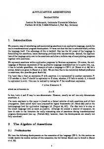
For example, in graph R depicted in Figure 1, V={a,c}, E={f}, label(a)=area, type(a)=operation, label(f)=uses, type(f)=uses, source(f)=a and target(f)=c. We distinguish types from labels by writing types in boldface.
Software transformations are also useful to provide support for refactoring application frameworks in a behaviour-preserving way. Refactorings improve the design or structure of objectoriented frameworks, making them more robust towards evolution [13, 14, 16].
Since graphs represent software artifacts, evolution of these artifacts can be expressed by graph rewriting. Because we will manipulate graph rewritings explicitly, they should be decoupled from the actual graphs to which they are being applied. This is achieved by introducing the notion of a graph production P: L R that transforms a source graph L into a target graph R. In order to apply this production to an initial graph G, a match m: L G is needed to specify which part of the initial graph G is
Æ Æ
For merging as well as refactoring, there is a need to express evolution transformations in a scalable way. Indeed, in practice, the software that is being developed as well as the software transformations that are applied to it can be quite large. A promising formal approach which has not yet been thoroughly explored is the use of assertions for expressing software *
Æ
3
Postdoctoral Fellow of the Fund for Scientific Research – Flanders (Belgium) (F.W.O.-Vlaanderen)
1
Primitive productions Relabel and Retype can be used for nodes as well as edges. We often use the notation RelabelN and RetypeN (resp. RelabelE and RetypeE) to stress that we are changing the label or type of a node (resp. edge).
being transformed. Together, P and m uniquely define a graph rewriting G ⇒P,m H. This graph rewriting also induces a co-match m*: R H that specifies the embedding of R in the result graph H.
Table 2: Positive wildcard assertions
Æ
Æ
As an example, consider the graph rewriting of Figure 1. The match m: L G maps node a of L on node 2 of G. The co-match m*: R H additionally maps node c of R on node 3 of H, and edge f of R on edge f of H.
Æ
L
R surface attribute
a
uses area f operation uses
P
a
1
surface e h a s - a attribute
2
1
Circle class
∃ E ∈ EdgeID: source(E) = N ∃ E ∈ EdgeID: target(E) = N
+target(*,N)
∃ N ∈ NodeID: source(E) = N
+source(E,*)
∃ N ∈ NodeID: target(E) = N
+target(E,*)
∃ L ∈ Label: label(Id) = L
+label(Id,*)
∃ T ∈ Type: type(Id) = T
+type(Id,*)
c
Some assertions automatically imply other assertions. For example, the absence of a node implies the absence of any label or type for this node, as well as the absence of any incoming or outgoing edges for this node. These implicit assertions are called derived assertions and are mentioned in Table 3. Whenever we specify a set of assertions S, we assume that all derived assertions are also included in this set, even if they are not specified explicitly.
H Circle class
Notation +source(*,N)
radius attribute
m G
Positive assertion
uses area e f h a s - a 2operation uses
radius attribute
3
Figure 1: An example of a graph rewriting
2.2 Assertions
Table 3: Derived assertions
Assertions are well established in the software community as a formal way to specify the behaviour of programs [7, 12]. Three kinds of assertions are distinguised. Preconditions must be satisfied for a certain operation to be applicable. Postconditions are guaranteed to be true after the operation has been applied. Invariants are assumptions that remain unaltered by the operation.
Assertion
Derived Assertions
-N
-label(N,*), -type(N,*), -source(*,N), target(*,N)
-E
-label(E,*), -type(E,*), -source(E,*), -target(E,*)
Another distinction is made between positive assertions, that indicate the presence of a certain property, and negative assertions that indicate its absence. Table 1 presents the positive assertions that can be expressed in our graph formalism, together with the notation used throughout this paper. Negative assertions are precisely the opposite: they express the absence of some entity in a graph, and are denoted by a minus sign. E.g., –source(E,N) expresses that edge E does not have node N as its source.
+source(E,N)
+E, +N
+target(E,N)
+E, +N
Positive assertion
Notation +Id
Edge E should have node N as its source
+source(E,N)
Edge E should have node N as its target
+target(E,N)
A node or edge Id should have label L
+label(Id,L)
A node or edge Id should have type T
+type(Id,T)
+Id
+type(Id,T)
+Id
2.3 Conditional Graph Productions The main distinction between our approach and the “common” use of assertions [7, 12, 15] is that we do not use assertions to attach behavioural constraints to programs. Instead, we use assertions to represent evolution transformations (as in [11, 16]). In other words, we attach assertions to graph productions rather than to graphs themselves.
Table 1: Positive assertions A node or edge with identifier Id should be present
+label(Id,L)
Each assertion can be used either as precondition, postcondition or invariant of a graph production P. The sets of all these assertions are denoted by Pre(P), Post(P) and Inv(P) respectively. We also use the shorthand notations Before(P) = Pre(P) ∪ Inv(P) and After(P) = Post(P) ∪ Inv(P). Given a graph rewriting G ⇒P,m H, one can easily write an algorithm that calculates the minimal set of assertions that determines the production P. For example, in Figure 1 we can identify the following minimal assertions:
We also want to express more general constraints like: "node N does not have any outgoing edges" or "node N is the target of at least one edge". The former constraint is expressed as source(*,N), and the latter as +target(*,N). All positive wildcard assertions used in this paper are enumerated in Table 2. Negative wildcard assertions are merely the negation of their positive equivalents. For example, -source(*,N) is the negation of ∃ E ∈ EdgeID: source(E) = N, i.e., ∀ E ∈ EdgeID: source(E) ≠ N
Pre(P) = {-c, -f, +label(a,surface), +type(a,attribute)} Inv(P) = {+a, -source(*,c)} Post(P) = {+label(a,area), +type(a,operation), +c, +label(c,radius), +type(c,attribute), +f, +source(f,a), +target(f,c), +label(f,uses), +type(f,uses)} If necessary, extra assertions can be added to these sets in order to restrict the applicability of production P to a smaller set of initial graphs. For example, if we would impose the extra invariant -
2
contradicts -a ∈ Before(P2). The sequence P1; P2; P3 = AddNode(a,l1,t1); RelabelN(a,l1,l2); RelabelN(a,l2,l3) is wellformed because the contradiction between +label(a,l1) ∈ After(P1) and +label(a,l2) ∈ Before(P3) is absorbed by +label(a,l2) ∈ After(P2).
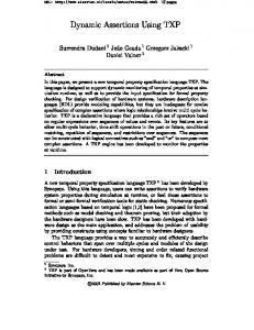
target(*,a), P would not be applicable anymore to the graph G of Figure 1. Following the notation of Perry [15], the assertions for production P are depicted as ellipses in Figure 2, while P is represented as a grey rectangle. Preconditions appear on the upper horizontal side of the rectangle, postconditions on the lower horizontal side, and invariants on the vertical sides. For positive assertions, the + sign is omitted in the figures. When they are needed, derived assertions are depicted by dashed ellipses. Finally, we abbreviated the last five postconditions of P to (f,a,c,uses,uses). -c
-f
label(a,surface)
a
type(a,attribute)
P
-source(*,c) c
Table 6: Contradicting assertions
(f,a,c, uses,uses)
label (a,area)
type (a,o peration)
label (c,radius)
type (c,attribute)
Figure 2: Graphical notation of a conditional production
Inv
-N
-source(*,N) -target(*,N)
+N +label(N,L) +type(N,T)
AddEdge (E,Ns,Nt,L,T)
-E
+Ns +Nt
+E +label(E,L) +type(E,T) +source(E,Ns) +target(E,Nt)
DropNode (N)
+N
-source(*,N) -target(*,N)
-N
DropEdge (E,Ns,Nt)
+E +source(E,Ns) +target(E,Nt)
+Ns +Nt
-E
Relabel (Id,L1,L2)
+label(Id,L1)
+Id
+label(Id,L2)
Retype (Id,T1,T2)
+type(Id,T1)
+Id
+type(Id,T2)
+A
-A
+A is some arbitrary positive assertion
+source(E,N1)
+source(E,N2)
N1 ≠ N2
+target(E,N1)
+target(E,N2)
N1 ≠ N2
+label(Id,L1)
+label(Id,L2)
L1 ≠ L2
+type(Id,T1)
+type(Id,T2)
T1 ≠ T2
Using the formalism of conditional graph rewriting, software merging can be formalised [11] by the notion of parallel independence [5]. Intuitively, two graph rewritings are parallel independent if they can be sequentialised in any order without changing the end result. Unfortunately, this definition does not specify what to do when two graph rewritings cannot be merged (read: sequentialised). If this is the case, we say that they give rise to a syntactic conflict. For example, suppose that graph G contains a node, and production P1 removes this node while P2 independently adds an edge originating from this node. This yields a syntactic conflict since trying to merge both parallel evolutions would lead to an edge without a source.
Post
AddNode (N,L,T)
where
Ill-formed production sequences can be used to detect syntactic merge conflicts. These typically occur when different software developers are making changes to the same software in parallel, and these changes need to be merged.
Table 5: Primitive graph productions Pre
Contradicts
3.2 Detecting Syntactic Merge Conflicts
[11] expressed every possible graph transformation in terms of a number of primitive productions that are sufficient to express any kind of change to a graph. For example, AddEdge(f,a,c,uses,uses) adds an edge f from a to c with label uses and type uses. Table 5 shows all primitive productions and their corresponding assertions.3 Graph Production
Assertion
Definition. Two graph rewritings G ⇒P1,m1 H1 and G ⇒P2,m2 H2 lead to a syntactic conflict if the production sequence P1; P2 (or P2; P1) is ill-formed. By comparing the different kinds of assertions that hold for P1 and P2, we can easily determine when a syntactic conflict occurs. It suffices to find a contradicting assertion between After(P1) and Before(P2), using Table 6. For example, for the primitive productions of Table 5 we identify the following syntactic conflicts:
3. PRODUCTION SEQUENCES
•
Prohibited node removal if -v ∈ After(P1) and +v ∈ Before(P2). This is for example the case if P1 = DropNode(v) and P2 = AddEdge(e,v,w,l,t). One cannot add an edge with a certain source node if this node has been removed before. Prohibited edge removal is defined similarly.
•
Dangling source if +source(e,v) ∈ After(P1) and source(e,v) ∈ Before(P2). This is for example the case if P1 = AddEdge(e,v,w,l,t) and P2 = DropNode(v). One cannot remove a node that still has outgoing edges. Dangling target is defined similarly.
•
Prohibited node introduction if -v ∈ Before(P2) and +v ∈ After(P1). Prohibited edge introduction is defined similarly.
3.1 Well-formedness A production sequence is a sequence of graph productions that can be applied successively. It is well-formed if the assertions imposed by a production in the sequence do not contradict assertions imposed by earlier productions. Definition. A production sequence P1; P2; ..; Pn is well-formed if ∀ Ak ∈ Before(Pk) with k ∈ {2..n}: if (∃ Ai ∈ After(Pi) with i