pkl(pld5,pld4,-,pld6,selection).. pld(plds,pldS,pld7,pst('sent=0")). pld(pld7,pA6,pld8, ,assign(amount,"amounttlV). pld(plda,pld7,pldg,,assign(send,"l'). pld(pld9 ...
-
Transformations in CASE tools A Compiler View Odd Ivar Lindland
John Krogstie
Faculty of Electrical Engineering and Computer Science The Norwegian Institute of Technology N-7034 TRONDHEIM, NORWAY Abstract
languages like DFD, ER, etc. are imprecise. Thus, the requirements cannot be exactly specified,making ambiguous models. Consequently, the range of systems thatconforms with the model is too wide to make a transformation feasible. To improve the understanding on how transformations better can be supported in CASE tools, this paper will use a compiler view. By regarding the architectural parts of transformational implementation using a traditional compiler architecture,requirements for how to integratea transformation component in a CASE tool are discussed. The paper is organized as follows: In Section 2 we introduce a general compiler architecture. The architecture will devise some basic facilities for a transformation component to be integrated in a CASE tool. Section 3 presents the PPP environment within which several transformations have been implemented. In Section 4 a specific transformation from PPP models to TEQUEL/C is presented and discussed with reference to the compiler architecture. Conclusions and further work are offered in Section 5.
This paper uses a traditional compiler architecture to discuss how a transformation component can be integrated in CASE tools. The architecture outlines some general requirements to the transjbrmatwn component as well as to the source and the target language. To illustrate this approach, the PPP environment is presented. Within this environment several transformations from PPP models to programs have been implemented. A specifrc t,ransformationfromPPP models to TEQUELIC is discussed with reference to the compiler architecture.
1 Introduction C4SE tools are expected to play an increasingly important role in information systems development. In order to improve both the productivity and quality of a CASE supported development process, transformational implementation is one emerging approach [3]. By formalizing different manual, time consuming and error sensitive devellopment tasks, they can be assisted by integrating a transformation component in the CASE tool. First, transformrations can be used to generate programs from diagrammatic: models. A less ambitious goal is to generate prototypes, which may contributeto the validation of the model. Second, transformationsmay be used to ensure consistency across specifications by generating consistent frameworks expre:ssed in another language perspective. Finally, transformations can be used to optimize models, specifications, and programs with respect to e.g., efficiency and readability. Allthough new and more advanced CASE tools are developed, transformational implementation is mainly a research topic and is only partly exploited in contemporary CASlE tools. Two major factors hamper a further exploitation [ 1,5,17]. First, the number of languages employed in CASlE tools is high and the languages are usually loosely couplled. This tends to create an information gap between the various parts of the models/specifications making the formalization of the integration difficult. Second, CASE
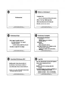
2 A General Compiler Architecture The principles for translating conceptual models to executable prototypes resemble well program compilation. To discuss the technical requirements for integrating a translation assistant in CASE environments, we will use the general architecture of a compiler as shown in Figure 1. The architecture performs the compilation of an input representation (program) to an output representation (machine code) through six phases. The output from one phase is input to the next. The purpose of the differentphases will be briefly described bellow. Also, the error handler and the symbol table for managing the compilation are described. Lexical analyzer reads the inputrepresentation to identify its different elements. A lexical analyzer for a 3GL program reads the program from left to right to group sequences of characters that have a collectivemeaning into tokens. 287
1066-:1387/93$3.00 0 1993 IEEE
I
I ~
~
Figure 1: A general compiler architecture. Adapted from [2]. stating which type of pattern should be triggered. The enabling condition is optional. A major requirement of a translation schema is that it should be meaning-preserving. That is, the translation rules should preserve the semantics of the input representation when generating the output. In cases of generating executable programs, there should be a well-defined correspondence between the execution semantics of the source language and the target langW9. Moreover, the translation schema should ensure traceability so that the input representation is kept trace of in the output representation. The translation schema should avoid, as much as possible, altering the structure of the source representation or introducing new variable or function names in the target representation. Thus, it shouldbe easy to modify the source representation on the basis of evaluating the target representation.
Syntax analyzer organizes the involved tokens into gram-
matical phrases that are used to synthesize the output. Grammatical phrases of a textual representation are often represented as parse trees. The major task of the syntax analyzer is to ensure thatthe program does not violate the grammar of the its language. Semantic analyzer checks whether the source program contains any semantic errors. In traditionalcompilers, type checking is a major activity in this phase. Intermediate code generator is used by some compilers to generate an intermediate representation that makes the final translation to the output representations easier. In some cases the intermediate represention is executable machine code. However, at this stage efficiency considerations have not been taken into account. Code optimizer attempts to improve the intermediate representation with respect to efficiency. A general approach for an optimizer is to reduce the number of instructions.
The Symbol Table keeps track of the identified tokens and their various attributes. For a 3GL program these attributes may provide information about the storage allocated for its identifier, its type, its scope, and argumenttpassing methods for procedure and function calls. Generally, a symbol table is a data structurecontaining a record for each identifier, with fields for the different attributes. Throughout the compilation phases, the information in the symbol table is used for differentpurposes. During the lexical analysis, the various tokens are detected and their corresponding identifiers are entered in the symbol table. Furthermore, in the semantic analysis, the type information is required.
Code generator executes the actual translationsby applying a transformution schema which consist of a set of transformation rules. The rules takes patterns of the intermediate representation and produce statements in the output representation. A translation rule can graphically be illustrated on the following form [4]:
(1) i is a pattern in or subset of the intermediate (input) representation ,(2) o is a pattern in or subset of the output representation,and (3) c is an enabling condition, 288
A
....
Registration
Reminder-info
1
-
, Illvoice
I
U
Uudate reminder
Figure 2 The PrM model of the Sweden Post.
The Error Handler reports on errors that are encountered during the compilation. A compiler should allow the compilation to proceed so that all errors in the source specificationcan be detected. Moreover, the detected errors should be reported in a readable fashion, explaining the place (e.g. code line) and the reason (e.g. “illegal symbol”)for the error.
In cases of generating executable programs, the source language should have a well-defined execution semantics that corresponds well with the execution semantics of the target language. Consequently, the transformation process can ensure thata correct executable program is generated.
3 The PPP Environment
A transformation component in a CASE tool should in many ways have the facilities as a traditional compiler. Most interesting in this paper is a transformation component which takes a diagrammatic specification as input and produce an executable program. According to the above architecture, the tasks of the transformation component shouldbe somewhat ordered. For instance, having a CASE tool which supporta specific diagram notation,the diagram syntax has to be checked prior to diagram transformation. If necessary the output from one task (phase) should be available as input to the next task. An error handler and a symbol table should be included to manage the transformationprocess. When errors are encountered, the error handler should give meaningful messages to the tool-user. The symbol table in a CASE tool context can be regarded as a storage structure which defines how a diagram is internally represented. In addition to architecturalaspects of the transformation component, specific properties of the source language and the target language is required. Both should have aformar s y n m on which the transformation rules can be defined.
PPP (Phenomena, Processes, and Programs)is an experimental CASE environment which is presented in [gl. A prototype version of the PPP tool is running on Sun workstation under Unix and Sunview and has been developed using BIM-Prolog as major implementation language. The tool provides modeling support for a set of integrated languages, the PPP language, covering different aspects and stages of systems development. Furthermore, it provides support for quality assurance of PPP models using different verification and validation techniques. Here, transformations play a major role. First, transformations are used to generate consistent frameworks from one sub-language to another. Second, and most interesting in this paper, transformations are used to generate executable prototypes so that the dynamic properties of the PPP model can be vali‘PPP isdevelopcdwithintheRHAPSODY-project(l989-1993)attheUniversity of Tmdheim and very much builds on and d a t e s to the results of the
DAISEE-pmject (1982-88).Fwthemom, cooperatimhastaken place towards the ESPRIT-projccts;TEMF’ORA and IMSE.
289
Invoice-info
I I
-
..................
*.**-
......pent .......... I
I
A
-
0
/‘”C“‘.
amount :=amount+lg..i---. . . . . . . . . . . . . . . . . . . . . . . . . . . . . . . . . . . . .
;
sent
I
Send Invoice ToAl
:I
1
:
Figure 3: A PLD model correspondingto the process interface of P2,
dated. In this section we will briefly introducethe PPP language and outline how a PPP model is represented in the tool. Furthermore,we will present parts of the verification support provided by the tool.
0
A Brief mste of the PPP Language
0
The PPP language consists of four sub-languageswhich are grounded on well established languages and is used to capture and model different aspects of the functional requirementsto an informationsystem:
The PLD ( P r ~ ~ eLife s s Description) language is used to specify process logic of undecomposed processes and has many similarities with a block-structured,visual program design language [201. The UID (User Interface Description) language is used to describe static and dynamic aspects of user interfaces, based on possibilities offered by graphical user interface technology.
In the remaining of this paper the properties of the PrM language and the PLD language are emphasized. To illustrate the basic concepts of these languages we have in Figure 2 depicted a PrM model of parts of the “Sweden Post Case Study” [191, considering the business area “Management of Invoicing and Payments of Delivery-notes. The basic modeling concepts of the PrM language are labeled. Moreover, in Figure 3 we have itlustrated the PLD model for process P2 :Invoicing. Also, here the basic concepts are labeled. More complete descriptionsof the CASE study and the PPP language are given in E191 and [6], respectively. From a transformation point of view the PrMPLD language has the following properties: First, the syntax of the PPP languages has beenformally defined both in a BNF notation [131, and in first-order logic [151. Second, compared to the original DFD language, the preciseness is improved in the PrM language. The triggering and termination flows has control properties stating how a process starts and stops, respectively. Moreover, input and output ports describe how the flow content is dis-
The PrM (ProcessModeling) language is used to describe dynamic, functional aspects of a system. It is based on the traditional DFD language, with added constructs for better precision and increased expressiveness. In particular, it suppom modeling of control, by triggering and terminating flows. It also allows process interfaces to be modeled using ports which form logical expressions (AND, XOR, OR, etc.) for legal combinations of input and output flows. The PrM language has many similarities with the Ward‘s TransformationSchema [21] and a language described by Kung [111. The PhM (Phenomenon Modeling) language is an extension of the ER language. It includes many features of newer semantic data modeling languages ([lS]), for instance subclassing and multivalued attributes. 290
pld(id,from,to,right,content).
amoUnt:=amount+lO Sent := 1
Send Update-invoice To D4 Send Invoice To A1
pldbldl, ,Pkn,,start) pld(pld2,pldl,pld3,,receive(mvoici~~hedu~)). pld@ld3,pld2,~pld4,while(Qta)). pld(pld4,prCr3,pldS, ,receive(imoice-info)). pkl(pld5,pld4,-,pld6,selection).. pld(plds,pldS,pld7,pst('sent=0")). pld(pld7,pA6,pld8, ,assign(amount,"amounttlV). pld(plda,pld7,pldg,,assign(send,"l'). pld(pld9,pld8,pldlO,- send(update_imoice)). pld(pld10,pk19,L,send(invoiced)).
(b)
Figure 4: The PLD model and its corresponding storage representation
tributted among the PrM modeling constructs. Third, the PrM language is executable relying on the fact that control and data is included within the same language. The execution semantics is defined by triggeringkerminating flows, port!$,and timers. Together with the algorithmic descriptions; from the PLD models, a PrMpLD model can be interpreted or transformed into executable programs.
structs defined in the PPP languages. In this way the tool restricts the possible tokens to be produced. Syntaxanalysis are supported in two ways: restricting and enabling. The PPP editors resembles syntaxdirected editors, in the way that drawing sessions that violates the language grammar is disrupted. For instance, it is not possible to build a direct flow from an agent to a store. This is immediately checked and thus restricts the modelingfreedom. However, to support some degree of modeling freedom, some syntax errors must be allowed on a temporary basis. These are possible to detect by letting the developer perform explicit checks. Here, the checks concerns the syntactical completeness of the model. For instance, a PrM process may lack an input flow throughout the drawing session, but this will be detected during the check.
Repiresenting a PPP model
To discuss details of the transformation components in PPP, the representation of a PPP model is essential. A PPP model is stored in the repository according to a defined storage schema for (1) the model structure, (2) the model content, and (3) the model layout. In the current prototype version, the storage schema is a Prologfact schema. That is, a PPP model is stored as Prolog facts in Unix-files which are the current storage medium. In1Figure 4 we have illustratedhow the PLD model from Figure 3 is stored as Prolog facts. The general schema for storing PLD constructs and the instantiated schema with respect to the PLD model is given.
When a PPP model is developed, the PPP tool provides diffeirent kinds of verification support. This support serves two imajor purposes. First, it ensures a certain quality of the nnodel. Second, and most interesting in this paper, it prepares the model for eventual transformations. The verification supported resembles the first phases (front-end)of the compiler architecture from Section 2:
Semantic analysis is supported to some extent by the PPP tool. First, PLD models are subject for type checking. That is, only PLD model contains typed values that are tested or transformed from the PrM model. PLD statements are checked for typecorrectness when they are constructed. For instance, the check ensures that items of a flow that enters a process has the same type as the ones that where sent in the sending process. Second, logical expressions that are formed by input and output ports are checked for inconsistencies. The check is performed both between processes on the same level of decomposition and between a mother process and her children. The checking algorithm very much builds on the one found in [113.
Lexical analysis is implicitly supported by the PPP tool. The PPP editors only provides the modeling con-
Although the verification support of PPP tool resembles the front-end phases of a traditional compiler, it should be
-
Veril6cation support Preparing the transformation
8
291
.
noted that the order of these tasks is not that strict and the output from one phase is not input to next. Here, the tasks are either triggered by the tool or by the developer. Also, all tasks are carried out on the same object - the PPP model. Intermediate code generator, Code optimizer, and Code generator are not directly relevant during the verification support, but will be addressed when a PPP model is transformed into a specific program. The Symbol Table and the Error Handler, on the other hand, are relevant during the verification support. Here, the symbol table can be regarded as an instantiation of the Prolog fact schema. Thus, as the verification syntactically and semantically accepts the model, the symbol table is successively created. Furthermore, the verification support may encounter model errors. In such cases, the error handler gives the developer messages about the error. This is particularly the case during the syntax analysis. If illegal model patterns are detected, their reasons are thoroughly explained.
The formula about the past is expressed in TQL, Temporal Query Language, whereas the formula about the future is expressed in TAL, Temporal Action Language 1161.
4 Transforming TEQUELJC
The Transformation Strategy
PPP
models
PPP model PhM
1
PrM
Model level
PLD
..--...........-....-......
I..
Program level
I
RuleManager
I
Executionlevel
Figure 5: The overall transformation strategy
into
The overall strategy for transforming PPP models to CDEQUEL programs is indicated in Figure 5. From a PPP model, three separate files are generated: (1) A TEQUEL file, (2) a Cfile, and (3) an Inferfacefile which acts as an interface between the C file and the TEQUEL file. Each file is generated based on a transformation schema that exploits different parts of the PPP model and the transformation strategy is informally explained as follows:
In the PPP environment, several transformations have
been implemented to generate programs on the basis of different parts of a PPP model. So far, these transformations are mainly restricted to the construction of prototypes. The most important transformations implemented in the PPP tool are: (1) from UID models to C/Motif ([9]), (2) from PLD models to Ada ([14]), (3) from PPP models to Simula/Demos ([8]), and (4) f ” PPP models to TEQUEL/C ([10,121). In the remaining of the paper, we will take a closer look at the generation of TEQUEL/C code. The transformation process will be presented and discussed with reference to the compiler architecture. First, however, a short introduction to TEQUEL.
The TEQUEL File contains the temporal statements based on the information given in the PrM model and the database schema created from the PhM model. The TEQUELprogram consists of the following parts: (1) a declare part which converts information from the environment into a form that is manageable by the Rule Manager, (2) a never part that consists of constraints expressed in the conceptual model, (3) a query part that consists of derivation rules, and (4) a rule part which consists of action rules [161. Generally, rules which can be interpreted from the PPP model are bansformed into TEQUEL rules that appear in the rule part. The effect of the TAL statement is specified in the declare part.
-
TEQUEL A short introduction TEQUEL is a programming language with temporal semantics that has been developed at Imperial College, London [161. The underlying execution platform for TEQUEL is called the Rule Manager [191. A TEQUEL specification is a set of rules on the form [lo]:
The C File corresponds to the internal behavior of the processes which are described by the PLD language. The procedural semantics of the PLD language makes a transformation to C straightforward, giving one C function for each PLD model. Selection constructs, iterative constructs, and assignment constructs have
formula about thefuture