International Journal of Electrical and Computer Engineering (IJECE) Vol. 6, No. 6, December 2016, pp. 2499~2505 ISSN: 2088-8708, DOI: 10.11591/ijece.v6i6.11406
2499
Transient Phenomena during the Three-Phase 300MVA Transformer Energization on the Transmission Network Emir Alibašić1, Predrag Marić2, Srete Nikolovski3 1
Umel-Dalekovodmontažad.o.o, Tuzla, Bosnia and Herzegovina Faculty of Electrical Engineering, Computing and Information Technology, J.J. Strossmayer University, Osijek Croatia
2,3
Article Info
ABSTRACT
Article history:
Connecting the transformer to the network may incur inrush current, which is significantly higher than the rated current of the transformer. The main cause of this phenomenon lies in the nonlinearity of the magnetic circuit. The value of the inrush current depends of the time moment of the energization and the residual magnetism in the transformer core. While connecting, the operating point of the magnetization characteristic can be found deep in the saturation region resulting in occurrence of large transformer currents that can trigger the transformer protection. Tripping of protection immediately after the transformer energization raises doubts about the transformer health. Inrush current can cause a number of other disadvantages such as the negative impact on other transformers connected on the same busbar; the increase of the transformer noise due to the large current value, the increase of the voltage drops in the network. The paper presents a simulation of the 300 MVA transformer energization using the MATLAB/Simulink software.
Received Jun 1, 2016 Revised Oct 5, 2016 Accepted Oct 19, 2016 Keyword: Inrush current MATLAB Simulink Residual flux Simulation Transformer modeling Transmission network
Copyright © 2016 Institute of Advanced Engineering and Science. All rights reserved.
Corresponding Author: Srete Nikolovski, Faculty of Electrical Engineering, Computing and Information Technology, J.J. Strossmayer University of Osijek, K. Trpimira 2 B, 31000 Osijek, Croatia. Email:
[email protected]
1.
INTRODUCTION Immediately after connecting the transformer with no-load on the grid voltage, the magnetic flux can reach two times higher value than nominal, which due to nonlinearity of the iron core affects the transformer current [1]. The maximum value of the current in this condition is higher as the cross-section of the winding gets closer to the cross-section of the ferit plates. It is noticed that the lower current value is obtained when the remanent flux value is lower and also when the transformer dimensions are smaller. The maximum value of current at no-load is calculated with use of numeric algorithms [2]. A high value of inrush current has a negative impact on the transformer mechanical stress and decreases the quality of electric energy [3-7]. In the paper [8] numerical calculations of inrush current of power transformers are presented. The value of inrush current falls on low value in few tenths of second, while the transient phenomena takes a few seconds [9]. In papers [10-14] are shown energizations of three-phase transformer with taking into account the effect of hysteresis loop, remanent magnetic flux and the moment of transformer enrgization. In paper [15] authors described scenarios of energization of power transformers depending on the moment of the enegergization. The problem of inrush current is expressed in three-phase transformers and also in singlephase transformers [16]. A mathematic model description of the three-phase transformer is shown in papers [17-18]. Magnetization curves and their approximations are given in papers [19-20]. High values of inrush current for real different cases of power transformer energization are given in papers [21-23].
Journal homepage: http://iaesjournal.com/online/index.php/IJECE
2500 2.
ISSN: 2088-8708
RESIDUAL FLUX At the time moment when the transformer is connected to grid, the voltage value is [3]: ( )
(
)
(1)
or voltage value can be written as: ( )
(2)
current i is calculated from differentional equation (2):
(
√
(
)
)
√
(
)
(
)
(3)
where is:
while the flux value is [3]: ( )
∫
(
)
(4)
In acordance to article [13] the residual core flux can raise up to 85% of the nominal flux but more typical magnitudes are in the range of 20 to 70% of the nominal flaux value. Analitical formulation of the maximal flux given in [1] and [11] is: (5)
3.
SIMULATION AND RESULT ANALYSIS The mathematical model was implemented in the software package Matlab / Simulink, and tested for a transformer whose parameters are shown in Table 1. Table 1. Nominal Data and Standard Parameters of the Three-phase Transformer-400 kV Substation Peja 3 – Kosovo Data Rated power primary / secondary Primay voltage Secondary voltage Frequency Parameters of primary winding Parameters of secondary winding Short circuit voltage
Value 300/300 MVA 400kV 115 kV 50 Hz V1 = 400 kV; R1 = 0.0018 pu; L1 = 0.076 pu V2 = 110 kV; R2 = 0.0018 pu; L2 = 0.076 pu 12.5 %
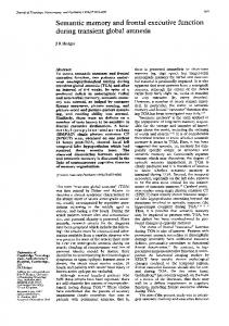
A computer model was developed in MATLAB / Simulink program. For the transformer model is used element named "Saturable Transformer," the transformer with two windings. The model takes into account the winding resistance (R1 R2 R3), the leakage inductances (L1 L2 L3), as well as the core magnetization characteristic. The transformer is connected to the network through the switch that connects the transformer at a given time momemt and thus simulates transients of all three phases. Oscillograms present voltage, current and the flux of the primary winding. Flux-current Characteristic as shown in Figure 1. The layout of the MATLAB / Simulink modeled transformer connected to the network is given in Figure 2. Simulations were pefromed for several cases of power transformer energization. Time momenets of energization and remanent magnetic flux values were taken into account. The simulations were performed for three different time moments of energization: t1=0.02 s; t2=0.0134 s; t3=0.0266 s in all three phases. The time IJECE Vol. 6, No. 6, December 2016 : 2499 – 2505
IJECE
ISSN: 2088-8708
2501
moment t1corresponds to phase L1, the time moment t2 corresponds to phase L2 and the time moment t3 corresponds to phase L3 of the real three phase transformer. In the real three-phase transformer energization transients in all three phases occur at the same time.
1.5
Flux (pu)
1 0.5 0
-0.5 -1 -1.5 -1
-0.5
0 Current (p u)
0.5
1
Figure 1. Flux-current Characteristic
Figure 2. Transformer Model Developed in MATLAB / Simulink Software Package
3.1. Energization of Simulated Transformer Model at the Time Moment t1 Figures 3 to 5 presents simulation results without remanent magnetism at t1. This is the time moment when the voltage value passes through the zero- point and the maximum magnetic flux is equal to the doubled nominal value. Energization of the simulated model represents transients of three phase transformer throug the first winding of phase L1. Oscillograms in Figures 3, 4 and 5 show the change in voltage, current and flux in the time interval of a one second. The transformer energization entails an adverse effect on the network, because in this case the growth of inrush current is up to about 4 times the exploitation. The voltage on the primary winding of the transformer has a nonsinusoidal shape because of higher harmonics occurence. The current on the primary winding reaches a value of 2.3 pu. To induce the counter votage to the connected voltage U1, a sine flux Ф appears in the transformer core, which lags behind the applied voltage for 900. Magnetizing current is not sinusoidal, as the halfperiod is symetrical, thus it contains odd sine and cosine harmonics [1].
Figure 3. Voltage on Primary Winding of Simulated Transformer without Remanent Magnetism at t1 in pu.
Figure 4. Current in Primary Winding of Simulated Transformer without Remanent Magnetism at t1 in pu.
Figure 5. Flux at the Primary of Simulated Transformer without Remanent Magnetism at t1 in pu.
Figure 6. Voltage on Primary Winding of Simulated Transformer with Remanent Magnetism Value of 0.75 pu. at t1 in pu.
Figures 6-8 present the results of simulations with remanent magnetism at energization at t 1. While energizing the transformer with remanent magnetism, higher values of energization current occure in than Transient Phenomena during the Three-Phase 300MVA Transformer Energization on … (Srete Nikolovski)
2502
ISSN: 2088-8708
without remanent magnetism. In the considered model with remanent magnetism, source current has a value about 4.16 pu. According to equation 5, the maximum flux value is increased by the value of residual remanent magnetism. In this case, the magnetizing current reaches a value of about 4.61 pu.
Figure 7. Current in Primary Winding of Simulated Transformer with Remanent Magnetism value of 0.75 pu at t1 in pu.
Figure 8. Flux at the Primary of Simulated Transformer with Remanent Magnetism Value of 0.75 pu at t1 in pu.
3.2. Energizing of the Simulated Transformer at the Time Moment t2 Figures 9 to 11 show the power transformer energization at the time moment t 2 without remanent magnetism in phase L2. Inrush current through the primary winding of simulated transformer is 0.92 pu. Figures 12 to 14 the power transformer energization at the time moment t 2 with remanent magnetism in phase L2. An evident disorder of the current source amplitude appears while the maximum current value reaches 1.3 times nominal value. The winding current of phase L2 is 0.14 pu.
Figure 9. Voltage on Primary Winding of Simulated Transformer without Remanent Magnetism at t2 in pu.
Figure 10. Current in Primary Winding of Simulated Transformer without Remanent Magnetism at t2 in pu.
Figure 11. Flux at the Primary of Simulated Transformer without Remanent Magnetism at t2 in pu.
Figure 12. Voltage on Primary Winding of Simulated Transformer with Remanent Magnetism Value of 0.75 pu at t2 in pu.
Figure 13. Current in Primary Winding of Simulated Transformer with Remanent Magnetism Value of 0.75 pu at t2 in pu.
Figure 14. Flux at the Primary of Simulated Transformer with Remanent Magnetism Value of 0.75 pu at t2 in pu.
IJECE Vol. 6, No. 6, December 2016 : 2499 – 2505
IJECE
ISSN: 2088-8708
2503
3.3. Energizing of the Simulated Transformer at Time Moment t3 Figures 15 to 20 show oscillograms of transformer energization at the time moment t 3 without remanent magnetism in phase L3. Energization current in this phase winding reaches 0.92 pu. Figures 21 to 23 show transformer energization at the time moment t3 with a remanent magnetism value of 0.75 pu, phase L3. The energization current reaches 0.23 pu.
Figure 15. Voltage on Primary Winding of Simulated Transformer without Remanent Magnetism at t3 in pu.
Figure 16. Current in Primary Winding of Simulated Transformer without Remanent Magnetism at t3 in pu.
Figure 17. Flux at the Primary of Simulated Transformer without Remanent Magnetism at t3 in pu.
Figure 18. Voltage on Primary Winding of Simulated Transformer with Remanent Magnetism Value of 0.75 pu at t3 in pu.
Figure 19. Current in primary winding of simulated transformer with remanent magnetism value of 0.75 pu at t3 in pu.
Figure 20. Flux at the primary of simulated transformer with remanent magnetism value of 0.75 pu at t3 in pu.
3.3. Analysis Results Simulations of transformer energization were performed at different time moments and different values of remanent flux. In the case 3.1 at the time moment of energization, the current is and the current ip from equation 3 have the same value but different signs and the resulting current as the sum of those two currents is zero. This corresponds to the expected physical phenomena at the beginning of the energization, because, independing on the value of the applied voltage v(t) (1), the winding current cannot be changed instantly. The role of the current ip is to ensure preservation of the initial values of i (3) at the time moment of the energization. Based on the current equation (3) it can be seen that the transient component of the current ip reaches its maximal value at α0=0° i.e. when the transformer is connected to the grid at the time moment when the voltage value is equal to zero. On the other side, when the transformer is conneted at the time moment when the voltage reachs maximal value -u1=U1m i.e. α0=90° equation (3), the transient current is zero. The energization current value depends on the value of the remanent magnetism at the moment of energization. The higher remanent magnetism value results in the higher energization current.The lowest value of the energization current is in the moment of the energization when the primary voltage value is the Transient Phenomena during the Three-Phase 300MVA Transformer Energization on … (Srete Nikolovski)
2504
ISSN: 2088-8708
highest and without presence of remanent magnetism.This occures at the first power transformer energization. In a three-phase system, voltages are phase-shifted by angle of 1200. To present a real transformer energization, simulations were carried out for three different values of AC sine voltage.The energization can occure in any time moment, or applied voltage value from equation (1) . For the phase L1 simulation is made when the voltage value pases through the zero point and energization current values are the highest, while in phases L2 and L3 occure increase of inrush current amplitude value, but in a smaller amount. Authors of paper [12] simulated a transformer with similar parameters and obtained the highest inrush current value of 2.59 pu (on the phase where the voltage pass zero point at the moment of energization).
4.
CONCLUSION The major influence on the inrush current make the value of connecting voltage and the value of the remanent magnetism in the transformer core at the moment of the energization.The inrush current value can be several times higher than the energization current. Such high current values can trip the transformer protection and thus make costs to the consumer and energy supplier. Simulations in this paper show inrush current in three different time moments of the power transformer energization. Maximal inrush current appeared at the time moment of the energization when the applied phase voltage value was zero with residual magnetism in transformer iron core.
REFERENCES [1] Dolenc, ―Transformatori I i II‖, Sveučilište u Zagrebu, Elektrotehnički fakultet, Zagreb, 1987, [2] Đ. Kalić, Transformatori, Zavod za udžbenike i nastavna sredstva, Beograd, 1991. [3] A.K. Al-Khalifah, E.F. El-Saadany, ―Investigation of Magnetizing Inrush Current in a Single-Phase Transformer‖, 1-4244-0557-2/06/©2006 IEEE. [4] N. Chiesa, B.A. Mork and H.K. Høidalen, ―Transformer Model for Inrush Current Calculations: Simulations, Measurements and Sensitivity Analysis‖, IEEE Transaction on Power Delivery, Vol. 25, No. 4, Oct. 2010. [5] M. Steurer, K. Fröhlich, ―The Impact of Inrush Currents on the Mechanical Stress of High Voltage Power Transformer Coils―, IEEE Transaxtion on Power Delivery, Vol. 17, No. 1, Jan. 2002. [6] Li-Cheng Wu, Chih-Wen Liu, Shih-EnChien, Ching-Shan Chen, ―The Effect of Inrush Current on Transformer Protection‖, Power Symposium, 2006. NAPS 2006. 38th North American, Carbondale, IL. [7] M. Nagpal., T.G. Martinich, A. Moshref, K. Morison, ―Assessing and Limiting Impact of Transformer Inrush Current on Power Quality‖, IEEE Transactions on Power Delivery, Vol. 21, No. 2, April 2006. [8] R. Yacamini and A. Abu-Nasser, ―Numerical calculation of inrush current in single-phase transformers‖, Electric Power Applications, IEE Proceedings B, (Volume: 128, Issue: 6), November 1981. [9] K. Karsai, D. Kerenyi, L. Kiss, ―Large Power Transformers‖, Oxford 1987. [10] G. Petrović, T. Kilić, O.nBego, ―Redustion of Inrush Currents at Three-phase PowerTtransformar Connection‖, Split, Croatia, Journal of Energy, vol. 57(2008), nr. 3, pages. 350-367 [11] S.D. Bole, ―Mitigation of Inrush Current in Transformer‖, International Journal of Innovative Technology and Exploring Engineering (IJITEE), ISSN: 2278-3075, Volume 3, Issue 7, December 2013 [12] John H. Brunke and Klaus J. Fröhlich, ―Elimination of Transformer Inrush Currents by Controlled Switching—Part I: Theoretical Considerations‖, IEEE Transactions on Power Delivery, Vol. 16, No. 2, April 2001. [13] M. Bukubukwana, R. Zivanovic, ―InrushCurremt Transients During Energization of an Unloaded Transformeron the Eskom Network, CIRED 2005‖, 18th International Conference and Exhibition on, Turin, Italy. [14] E. Cazacu, V. Ionita, L Petrescu, ―An Improved Method for the Inrush Current Evaluation in Single Phase Power Transformers‖, Advanced Topics in Electrical Engineering (ATEE), 2013 8th International Symposium on 23-25 May 2013, Bucharest. [15] S.A.M. Mirkalaei, F. Hashiesh, ―Controlled Switching to Mitigate Power Transformers Inrush Current Phenomenon‖, Power Engineering Conference (UPEC), 2015 50th International Universities, 1-4 Sept. 2015, Stoke on Trent [16] Yacamini R., Abu-Nasser A., ―The calculation of inrush current in three-phase transformers‖, Electric Power Applications, IEE Proceedings B, Vol. 133, Issue 1, January 1986. [17] S.G. Abdulsalam, W. Xu and V. Dinavahi, ―Modelling and simulation of three-phase transformers for inrush current studies‖, Generation, Transmission and Distribution, IEE Proceedings, Vol. 152, Issue 3, May 2005. [18] L. Donoxia, W. Zanji, L. Xiucheng, ―Modeling and Simulation of Magnetizing Inrush Current of Large Power Transformers‖, Electrical Machines and Systems, 2001. ICEMS 2001. Proceedings of the Fifth International Conference Vol. 1, Shenyang. [19] S.G. Abdulsalam, W. Xu, X. Liu, ―Estimation of Transformer Saturation Characteristics From Inrush Current Waveforms‖, IEEE Transaxtion on Power Delivery, Vol. 21, No. 1, Jan. 2006. [20] C.G.A. Koreman, ―Determination of the Magnetizing Characteristic of Three-phase Transformars in Field Tests‖, IEEE Transactions on Power Delivery, Vol. 4, Issue 3, Jul 1989.
IJECE Vol. 6, No. 6, December 2016 : 2499 – 2505
IJECE
ISSN: 2088-8708
2505
[21] M.M. Saied, ―A Study on the Inrush Current Phenomena in Transformer Substations‖, Industry Applications Conference, 2001. Thirty-Sixth IAS Annual Meeting. Conference Record of the 2001 IEEE (Volume 2), Chicago, IL, USA [22] A.R. Sedighi, M.R. Haghifam, ―Detection of inrush current in distribution transformer using wavelet transform‖, Electrical Power and Energy Systems, 27 (2005) 361–370, http://www.elsevier.com/locate/ijepes. [23] P.C.Y. Ling, A. Basak, ―Detectuin ofMagnetising Inrush Current Using Real Time Integration Method‖, Journal of Magnetism and Magnetic Materials, 83 (1990) 559-561 North-Holland.
BIOGRAPHIES OF AUTHORS Emir Alibašić, Dip l.ing. Electrical Engineer was born in Tuzla on March 12, 1982. He obtained his BCs degree (2007) in Tuzla in field of Electrical engineering at the Faculty of Electrical Engineering, University of Tuzla. Currently he is a PhD student at Faculty of Electrical Engineering, J.J. Strossmayer, University of Osijek, Croatia. His main interests are power transmission lines and optimization of electrical energy transmission. Currently he is employed at UMEL-DALEKOVODMONTAZA Tuzla on the position of design and conduct of business in the electricity objects up to 400 kV and owner INFORM Agency for the development of software applications .
Predrag Marić, PhD. El. Eng, was born on 11 December 1979 in Osijek. He obtained diploma degree in 2004 and PhD degree in 2010. in field of Electrical Power Engineering. Currently he works as assistant professor at the Power System Department at the Faculty of Electrical Engineering, Computer Science and Information Technology in Osijek. His main interest is power system stability analysis and transient phenomena in power system analysis. He is IEEE member and member of Croatian National Committee of CIGRE
Srete Nikolovski, PhD. MSc. El. Eng. (IEEE M’1995, SM’2005) was born in Belgrade on October 1, 1954. He obtained his BSc degree (1978) and MSc degree (1989), in electrical engineering at the Faculty of Electrical Engineering, University of Belgrade and his PhD degree from the Faculty of Electrical and Computing Engineering, University of Zagreb, Croatia in 1993.Currently he is a Full Professor at Power Engineering Department at Faculty of Electrical Engineering, J.J. Strossmayer University in Osijek, Croatia. His main interests are power system protection, power system modeling, analysis, simulation and reliability. He has published 180 technical papers in journals and international conferences. He is a Senior Member of IEEE Reliability Society, PES Society and the member of Croatian Committee of CIGRE
Transient Phenomena during the Three-Phase 300MVA Transformer Energization on … (Srete Nikolovski)