Translating the Feature-Oriented Requirements Modelling Language to Alloy David Dietrich, Pourya Shaker, Jan Gorzny, Joanne Atlee and Derek Rayside
[email protected] David R. Cheriton School of Computer Science University of Waterloo Waterloo, Ontario
Tech. Rep. CS-2012-12
1
Contents 1 Introduction
5
2 FORML
5
3 Alloy
7
4 Interactions
10
5 Translation Semantics 5.1 Structure of the Alloy output . . . 5.2 Translation of the World Model . . 5.2.1 Concepts . . . . . . . . . . . 5.2.2 Associations . . . . . . . . . 5.2.3 Messages . . . . . . . . . . . 5.2.4 Features . . . . . . . . . . . 5.2.5 Enumerations and Macros . 5.3 Translation of the Behaviour Model 5.3.1 World Change Actions . . . 5.3.2 States . . . . . . . . . . . . 5.3.3 Transitions . . . . . . . . .
11 11 12 13 15 16 16 17 17 17 18 18
. . . . . . . . . . .
. . . . . . . . . . .
. . . . . . . . . . .
. . . . . . . . . . .
. . . . . . . . . . .
. . . . . . . . . . .
. . . . . . . . . . .
. . . . . . . . . . .
. . . . . . . . . . .
. . . . . . . . . . .
. . . . . . . . . . .
. . . . . . . . . . .
. . . . . . . . . . .
. . . . . . . . . . .
. . . . . . . . . . .
. . . . . . . . . . .
. . . . . . . . . . .
. . . . . . . . . . .
. . . . . . . . . . .
. . . . . . . . . . .
. . . . . . . . . . .
. . . . . . . . . . .
. . . . . . . . . . .
. . . . . . . . . . .
. . . . . . . . . . .
6 Analysis 18 6.1 Checking all world states . . . . . . . . . . . . . . . . . . . . . . . . . . . . . . . 20 6.2 Saving the set of world states . . . . . . . . . . . . . . . . . . . . . . . . . . . . 21 7 An Example
22
8 Limitations
23
9 Conclusion
24
A FORML Grammar
26
B Textual FORML Model of the BDS Example
28
C FORML to Alloy Translation Rules C.1 World Model to Alloy . . . . . . . . C.1.1 Undefined Types . . . . . . C.1.2 Enumerations . . . . . . . . C.1.3 Concepts . . . . . . . . . . . C.1.4 Constraints . . . . . . . . . C.2 World-Model Expressions to Alloy . C.2.1 Parenthesized Expressions . C.2.2 Set Expressions . . . . . . . C.2.3 Integer Expressions . . . . .
. . . . . . . . .
. . . . . . . . . 2
. . . . . . . . .
. . . . . . . . .
. . . . . . . . .
. . . . . . . . .
. . . . . . . . .
. . . . . . . . .
. . . . . . . . .
. . . . . . . . .
. . . . . . . . .
. . . . . . . . .
. . . . . . . . .
. . . . . . . . .
. . . . . . . . .
. . . . . . . . .
. . . . . . . . .
. . . . . . . . .
. . . . . . . . .
. . . . . . . . .
. . . . . . . . .
. . . . . . . . .
. . . . . . . . .
. . . . . . . . .
. . . . . . . . .
31 31 31 31 32 35 35 35 36 37
C.2.4 Predicates . . . . C.2.5 @pre . . . . . . . C.3 WCA Types to Alloy . . C.3.1 Create Object . . C.3.2 Remove Objects . C.3.3 Change Attribute C.4 Assertions . . . . . . . .
. . . . . . . . . . . . . . . . . . . . Value . . . .
. . . . . . .
. . . . . . .
. . . . . . .
. . . . . . .
. . . . . . .
. . . . . . .
. . . . . . .
. . . . . . .
. . . . . . .
. . . . . . .
. . . . . . .
. . . . . . .
. . . . . . .
D Partial Generated Alloy Model of the BDS Example
3
. . . . . . .
. . . . . . .
. . . . . . .
. . . . . . .
. . . . . . .
. . . . . . .
. . . . . . .
. . . . . . .
. . . . . . .
. . . . . . .
. . . . . . .
. . . . . . .
. . . . . . .
. . . . . . .
37 38 38 38 40 40 41 43
Abstract The Feature-Oriented Requirements Modelling Language (FORML) provides explicit support for modelling Software Product Lines and systems that are composed of features. However, a problem that developers must be aware of when developing feature oriented software are interactions between features. The purpose of this project is to provide a method for analyzing FORML models to detect interactions that may occur. To this end a translator has been created that will translate FORML models into Alloy models so that they can be analyzed to show a lack of unwanted interactions. This report discusses the implementation of this translator, gives several examples of how various structures in the FORML are translated and discusses the methods of analysis that have been implemented. A small evaluation is also performed to demonstrate how the translator can be used in practice.
4
1
Introduction
Feature-oriented software development (FOSD) favours the treatment of features as first-class entities during all development phases. A major benefit of FOSD is the ability to decompose a software project into features such that multiple products can be derived from different combinations of features. A negative side effect of FOSD is that the features may not be separate concerns: they may conflict over the values of shared variables or may indirectly interact with each other over their effects on their environments [3]. Researchers at the University of Waterloo are developing the Feature-Oriented Requirements Modelling Language (FORML) [10], which is a general-purpose requirements modelling language designed to support software product lines (SPLs) and feature-oriented software development. This report presents a translator from the FORML into Alloy [5] that has been implemented for the purpose of automatically detecting several kinds of unintended interactions between features in a FORML model. The translator generates assertions that encode the effects of two features actions executing at the same time – if the actions conflict then the analyzer produces a world state (i.e., a set of specific values of the model’s variables) in which the actions conflict. Something to note is that the analyzer need not be used purely to detect interactions. A user could write their own assertions to verify other facts about their translated FORML model. It is also possible to use the analyzer to generate valid world states in order to visualize the context in which the features are executing. The rest of this report is organized as follows. Sections 2 and 3 provide brief introductions to the FORML and Alloy languages – knowledge that the reader needs to understand the rest of the report. Section 4 introduces the FORML definition of an interaction and our methodology for detecting interactions. Sections 5 and 6 discuss the semantics of the translation process and the resulting Alloy output, and provide information about the analysis that is performed to verify the FORML model. Sections 7, 8 and 9 provide a small example, some limitations of the translator, and concluding remarks. There are also several appendices included which provide additional information to supplement this report.
2
FORML
The Feature-Oriented Requirements Modelling Language (FORML) is a general-purpose modelling language that supports software product lines (SPLs) and feature-oriented software development (FOSD). The FORML is composed of three models: a world model, a feature model and a behaviour model. The feature model is a typical feature-oriented domain analysis feature model [3]; it expresses whether a feature is mandatory or optional, and dependencies between features, in an SPL product. The rest of this section explains the world and behaviour models briefly; more can be found in a technical report by Shaker and Atlee [10]. A world model defines all of the world phenomena that are relevant to the requirements of a particular set of features. In other words, the world model specifies the context in which the features operate. A world model is very similar to a UML 2.0 [1] domain model. The example in Figure 1 shows a simple world model. The example model contains an abstract superclass PhysicalObject that has a position and a shape. Inheriting from a PhysicalObject are 5
Figure 1: A World Model with a single feature RoadObjects, RoadSegments and Lanes. A RoadSegment contains one or more Lanes, and a RoadObject is on a single RoadSegment. A RoadObject could be anything on the road (e.g., a rock or animal). A special type of RoadObject is an AutoSoftCar that is a car that is running the specified AutoSoft features. An AutoSoftCar has a Driver who is driving the car. The AutoSoftCar concept specifies attributes that are specific to a car. You can see in the Figure 1 that there are two additions to the world model that are not found in regular UML domain models. The first is the AutoSoft concept: this is the SPL that is being modelled. The composition relation between AutoSoftCar and AutoSoft shows that an AutoSoftCar is running an instance of the AutoSoft SPL. The second addition is the BDS feature in the bottom left corner of the model. Each feature type in the world model specifies any feature-specific data the feature introduces, the input messages to the feature, and the output messages from the feature (denoted as «inputs» and «outputs», respectively). A message is a type of communication to or from a feature in an SPL. Dependencies among features are captured in a FORML feature model (not shown). The corresponding FORML behaviour model specifies how each feature reacts to input messages and generates output messages. A FORML behaviour model is expressed as as set of extended finite-state machines (similar to UML state machines [1]). A behaviour model is decomposed into separate finite-state machines for each feature. Each feature’s state machines are referred to as the feature’s module. A feature module can either specify new behaviour or override the behaviour defined in other feature modules. An example of a behaviour model for the Basic Driving Service (BDS) feature is shown in Figure 2. In the top left corner of the figure is a UML note that declares that this model specifies the behaviour of the BDS feature in the AutoSoft SPL. States and concurrent regions in a FORML behaviour model are no different than those in UML state machines. Each transition 6
Figure 2: A Behaviour Model for the Basic Driving Service corresponding to the above World Model must have a unique identifier (e.g., t1). Transitions have triggers and guard conditions as in UML state machines. A transition can have a list of actions, called world-change actions (WCAs). There are four types of WCAs: (1) adding an object to the world, (2) adding a message to the world, (3) removing an object from the world, and (4) changing an attribute value of an object in the world. The transitions in the BDS behaviour model in Figure 2 exhibit only one type of WCA: changes to attribute values. Multiple WCAs on a transition represent concurrent actions. Lastly, transitions may specify an override: in the BDS state machine in Figure 2, the override “t4 > t3” states that if transitions t4 and t3 are simultaneously enabled, then transition t4 has priority and t3 does not execute.
3
Alloy
Alloy is a general-purpose declarative modelling language. In Alloy, users can define the structure of their model and the Alloy analyzer will automatically create instances that conform to that structure. Users can also define constraints that must hold on the generated instances. Properties of the model can be checked automatically and the analyzer will provide feedback. This section provides a brief introduction to Alloy as some knowledge of the language is required to understand this report. A running example is used in this section that creates a simple model of a bird. The primary structural construct in Alloy is the signature. A signature is denoted in the Alloy syntax as sig. A signature in Alloy is an atomic element (another way to think of signatures is as types, similar to classes in UML class models). A signature can have fields (in the same way that UML classes have attributes). A field can express a relationship between its signature and other signatures. An example of a signature is:
7
1 s i g Bird { 2 s p e c i e s : SpeciesType 3 f o o t : FootType 4 }
This signature models a bird. A bird has two fields: a species and a foot. The types of these fields are SpeciesType and FootType, respectively. SpeciesType and FootType are nonstructured types; they are specified as enumerations (i.e., a set of constants). The SpeciesType and FootType in the Bird signature are represented in Alloy as: 5 enum S p e c i e s T y p e { goose , penguin , duck } 6 enum FootType { claw , paw , h o o f }
The fields of a signature can be much more complex than what is shown above. For instance, we could create another signature Flock. A flock has a single field: birds : set Bird. This field states that there is a set of birds (that is, some collection of birds) within a flock. The user could specify the number of birds in a flock by using a fact. A fact is an invariant constraint that must hold in all of the instances of a model. Facts can be used to constrain the structure or kinds of values that instances of a model can have. Facts are very closely related to OCL invariants [2]. An example of a fact is: 7 f a c t footType { 8 a l l b : Bird | b . f o o t = claw 9 }
This fact states that for all birds in the model, the bird’s foot must be a claw. In general, a fact is a first-order boolean formula. A weaker version of facts are predicates. A predicate is a boolean property applied to designated elements of model instances. For instance, the predicate: 10 pred f l y s ( b : Bird ) { 11 b . s p e c i e s != penguin 12 }
applies to parameter b – the predicate is true only if b is a Bird but is not a penguin. A predicate can be left empty, in which case it is always true. A predicate can also refer to other predicates. Predicates are used with the run keyword to generate instances of an Alloy model. Running a model will generate valid instances of the model that adhere to the model’s signatures and facts. When a predicate is used with the run command, the predicate must also be true of all the instances that are generated. The Alloy analyzer generates instances by transforming the 8
Alloy model into a set of conjunctive-normal-form formulas that are fed into a back-end SAT solver, which finds variable assignments for which the formula holds true. A nice feature of Alloy is the visualizer. The visualizer presents instances of an Alloy model in a graphical format that is sometimes easier to understand than a textual equation. Figure 3 shows the visualized output from the analyzer for an instance of the command run flys (the predicate given above). You can see in this figure a Bird object and its associated species and foot values. This is not the only instance that can be generated; there are several possible valid instances that conform to the structure of our model. A user can iterate through all of the possible valid instances using the Alloy visualizer.
Figure 3: An example of an instance of the Bird model. The instance is generated by the command run flys, the output of the Alloy visualizer shows a model than conforms to the structure and constraints defined. In addition to facts and predicates, which are always or sometimes, respectively, forced to hold in all instances of a model, a modeller can also specify assertions. Alloy assertions are analogous to programming-language assertions, in that they express assumptions that the modeller expects to hold of all valid world instances. If there exists a valid model instance for which the assertion is false, then a counter-example is generated. Consider the following assertion over our bird model: 13 a s s e r t checkType { 14 a l l b : Bird | f l y s [ b ] i m p l i e s b . s p e c i e s = g o o s e 15 }
This assertion states that for any Bird object, if the flys predicate holds true for that bird, then the bird’s species must be equal to goose. Intuition would indicate that this is false because it is also possible for a bird to fly and be a duck. This assertion can be checked by using the check command (and providing the assertion checkType as an argument). Figure 4 shows the command and a generated counter-example. This counter-example backs up our intuition by showing a model instance that includes a bird object whose species is duck. If there is more than one counter-example then the user can iterate through them in the same way the user can iterate through instances. After viewing the counter-examples, the user can decide whether to modify the assertion or the model, so that the assertion is satisfied. This short introduction should make it possible to read the remainder of the report without 9
Figure 4: The output from the checkType assertion. The checkType assertion is checked using the command check checkType. A counterexample is generated and visualized on the right. any additional information about Alloy. However, this has hardly been an exhaustive introduction to the language. Much more information on Alloy can be found in the book: Software Abstractions by Jackson [5].
4
Interactions
In the FORML, a feature interaction occurs when two transitions from different features attempt to change the same part of the world at the same time. This definition also applies to transitions executing in concurrent regions within the same feature. In this work, we have extended the notion of an interaction to also include checking the actions of a single transition. For example, an interaction occurs when the actions of two concurrently executing transitions change the same attribute value of the same world object; the result is an inconsistency if the two new values of the attribute conflict. Simultaneous changes to an attribute value is an obvious interaction, but non-obvious interactions may also occur. When a transition’s actions remove an object from the world, this can indirectly cause the removal of several objects from the world (e.g., removing an object that is composed of other objects will remove the component objects as well). An interaction can also occur when the result of two transitions’ actions violate a constraint on the world. We are most interested in detecting these kinds of non-obvious interactions. As will be seen, the definition of an interaction has been generalized, so it is not necessary to identify all of the possible types of interactions that may occur. It is possible for a single transition to result in an inconsistent state, either because a transition’s multiple actions interact, or because the action violates some world state constraint (e.g., adding an object to an association that violates a cardinality constraint). The goal of the analysis is to provide early feedback to developers of FORML models so that they can take corrective actions to resolve these interactions at the requirements stage. An interaction can be resolved in several possible ways: changing a transition’s actions, giving one transition priority over another, or specifying that a pair of features can not be included in the same SPL product, and so on. However, resolution of interactions is outside the scope of this report.
10
Figure 5: An overview of how the translation from FORML to Alloy takes place
5
Translation Semantics
An overview of the translation process is given in Figure 5. The input to the translator is a FORML model expressed in textual syntax (the syntax definition of FORML’s textual syntax is given in Appendix A). An example of a textual FORML model (including a world model and behaviour model) is provided in Appendix B. The translator expects the input model to be complete and correct. If this is not the case, the translation may fail due to missing information, or the translation may complete but the generated Alloy model will be incorrect. The translation between FORML and Alloy is one way: information is lost during the translation making it impossible to reverse engineer an Alloy model and get back the original FORML model. The translator is written in the Turing eXtender Language (TXL) [6]. This is a text-based pattern-matching language that is useful for creating model-to-model translators. It is not as powerful as a compiler, but is sufficient for this translation problem. The rest of this section describes the translation by way of examples. All of the examples follow the convention of showing the FORML graphical representation, the corresponding FORML textual representation, and the translated Alloy output. Precise definitions of the translation rules are given in Appendix C.
5.1
Structure of the Alloy output
The structure of the Alloy output from the translator follows a strict ordering: 1. Type signatures 2. World state (WS) definition 3. World-state constraints predicate 11
4. World-state-transition constraints predicate 5. Enumerations 6. World-change actions 7. Transitions 8. Interaction assertions The type signatures define types for all of the concepts that exist in a FORML world model. The world state is defined as a large type signature. This type signature includes sets of all the concepts in the world model, as well as their attributes and the relationships between concepts. An instance of the world state is a single instance of a concrete world state for the corresponding FORML model. The purpose of defining world states this way is to collect all of the information about world states in a single Alloy type signature. This eases the translation of constraints on the world model and keeps the interaction analysis as simple as possible. The world-state constraints (WSC) predicate contains constraints on a single world state such as cardinality constraints and constraints related to entity values. The world-statetransition constraints (WSTC) predicate specifies constraints on how a world state can change; they are constraints over consecutive world states. The WSC and WSTC are specified as a single predicate to make it easier to explicitly check if a transition (or pair of transitions) violates the constraints when they execute. Enumerations are translated directly from a FORML model into Alloy. Each world change action (WCA) is modelled as a predicate that expresses the post conditions for that action. There are four kinds of world change actions that are possible in FORML: (1) adding an object to the world state, (2) adding a message to the world state, (3) removing an object from the world state, and (4) changing an attribute of an object in the world state. These four actions can occur for almost every concept in the world (with a few constraints [10]). Thus, this section of the generated Alloy model may contain hundreds (or even thousands on larger models) of predicates. A majority of these may never be used, but their presence does not affect the performance of the analyzer. The transitions section of the Alloy model contains a predicate for every transition in a FORML behaviour model. A transition predicate is the conjunction of WCA predicates of the FORML transition’s actions. The final section lists the interaction assertions. These are the assertions that are created to test for interactions that may occur when transitions execute. These and the transitions are explained in greater detail in Section 6.
5.2
Translation of the World Model
The entire world model of a FORML model is translated into Alloy. This is done because actions on transitions can affect any concept in the system’s world, so every concept is a potential site of interactions.
12
c o n c e p t RoadObject
s i g P h y s i c a l O b j e c t {} a b s t r a c t s i g WS { RoadObjects : s e t RoadObject }
Figure 6: An example translation from a concept in the world model. Top left is the FORML Graphical Model, top right is the FORML plain text model and on the bottom is the Alloy translation. 5.2.1
Concepts
Individual concepts in a FORML world model are declared as Alloy signatures. For each concept signature, a set of elements of that signature is defined in the world-state signature, to represent the set of concrete elements in a concrete world state. An example of concept translation is given in Figure 6, which translates a concept called RoadObject into Alloy. Inheritance of concepts is supported. This is expressed in the FORML textual syntax by saying that one concept extends another. Constraints are added to the WSC predicate to ensure that if there are subtype elements in a world state, they must be members of the set of the super-type. If the super-type is abstract, then another constraint stating that it can not be instantiated is also added to the WSC predicate. A limitation of this approach is that only single inheritance is supported in the translator [5, 7]. An example of concept-inheritance translation is given in Figure 7, which translates the RoadObject from the previous example and its abstract super-type PhysicalObject into Alloy. Attributes on concepts are represented in Alloy as relations that relate objects to values of the attribute’s signature. A unique name is created for the attribute by concatenating the concept name and attribute name (e.g., concept_attribute). Attributes have a multiplicity associated with them. In the FORML graphical syntax, if an attribute’s cardinality is not specified, it is treated as unspecified. However, in a textual FORML model, attribute cardinalities must be made explicit to generate a correct Alloy model. An attribute’s cardinality is modelled in Alloy as a fact, to reflect that cardinalities are inviolable. In contrast, the constraints expressed in the WSC are to be upheld by the system being modelled and we want to detect when a feature violates such constraints. An example of an attribute translation is given in Figure 8, which translates an attribute speed on the RoadObject concept. The type of an attribute may be undefined. In this case, a new signature is added to the Alloy type-signatures section that acts as a placeholder for that type. For example, if the speed attribute used in the example above were instead an undefined type T, then a sig T {} would have been added at the beginning of the Alloy model and the relation RoadObject_speed would have been RoadObjects -> T.
13
abstract concept PhysicalObject c o n c e p t RoadObject e x t e n d s P h y s i c a l O b j e c t
s i g P h y s i c a l O b j e c t {} s i g RoadObject {} a b s t r a c t s i g WS { PhysicalObjects : set PhysicalObject , RoadObject : s e t RoadObject } pred WSC ( ws : WS) { ( ws . RoadObjects = ws . P h y s i c a l O b j e c t s & RoadObject ) ( ws . P h y s i c a l O b j e c t s = ws . RoadObjects ) }
Figure 7: The example translation from a concept with inheritance to Alloy. Top left is the FORML Graphical Model, top right is the FORML plain text model and on the bottom is the Alloy translation.
c o n c e p t RoadObject a t t r i b u t e speed [ 1 ] : Int
s i g RoadObject {} a b s t r a c t s i g WS { RoadObjects : s e t RoadObject , RoadObject_speed : RoadObjects −> I n t } { a l l o : RoadObjects | #(o . RoadObject_speed ) = 1 }
Figure 8: An example translation from a concept with attributes into Alloy. Top left is the FORML Graphical Model, top right is the FORML plain text model and on the bottom is the Alloy translation. 14
c o n c e p t Car concept Driver aggregation Drives whole r o l e c a r [ 1 ] : Car part r o l e driver [ 1 ] : Driver s i g Car {} s i g D r i v e r {} s i g D r i v e s {} a b s t r a c t s i g WS { Cars : s e t Car , Drivers : s e t Driver , D r i v e s s : s e t Dr i v es , Drives_car : D r i v e s −> Car , D r i v e s _ d r i v e r : D r i v e s −> D r i v e r } pred WSC ( ws : WS) { ( a l l c a r : ws . Cars | # ( ( ( ( ws . Drives_car ) . c a r ) ) . ( ws . Drives_car ) ) = 1 ) ( a l l d r i v e r : ws . D r i v e r s | # ( ( ( ( ws . D r i v e s _ d r i v e r ) . d r i v e r ) ) . ( ws . Drives_driver ) ) = 1) ( a l l o : ws . D r i v e s s | not o . ( ws . Drives_car ) = o . ( ws . Drives_car ) ) }
Figure 9: An example translation from an association in the world model to Alloy. Top left is the FORML Graphical Model, top right is the FORML plain text model and on the bottom is the Alloy translation. 5.2.2
Associations
Associations, aggregations and compositions have similar representations in Alloy. The roles on associations are represented as relations in Alloy that relate the associated concepts to each other. The cardinality constraints on each end of an association are added as constraints to the WSC predicate. An example of translating a FORML association is given in Figure 9, in which Car and Driver are concepts that are associated by aggregation (e.g., a Car has a Driver). As can be seen in Figure 9, associations are modelled the same as concepts are: as signature types that have instances in the world state. We chose this representation for associations because it allows associations to have attributes (e.g., association classes). Figure 10 visualizes an instance of a world state of the Alloy model in Figure 9 in which there is an association (i.e., a Drives object) with each association role being a relation to a Car and Driver object, respectively. Aggregations have an additional constraint added to the WSC predicate that specifies that an object cannot be a part of itself [9]. Additionally, compositions have a constraint added to the WSTC predicate that specifies that components (i.e., part roles) of a composition must belong to the same composite object (i.e., whole role) throughout their lifetime.
15
Figure 10: An example of the Alloy output for a simple associations between a Car and a Driver. The Drives triangle is the association itself. 5.2.3
Messages
Message types are also modelled as concepts. Similar to other concepts, a message type can be inherited from by another message type, be abstract, and have attributes. Messages can be input messages, output messages, or both input and output messages. Depending on whether a message is an input or output, it will have a relation that associates the message with its source and/or destination feature. In addition, message objects are transient, which means they can not exist in two consecutive world states. For this reason, a WSTC constraint is added for every message concept to express that if a message exists in a world state, then it can not exist in a next world state. 5.2.4
Features
The last major part of a FORML world model that is translated into Alloy are the feature concepts. The FORML textual syntax does not directly correspond to the representation of features in the world model. The textual syntax represents attributes and messages on features as well as the hierarchy of features and cardinality of features that are located in the FORML feature model. In most aspects, a FORML feature is translated in the same way that other concepts are. Features may contain attributes, a list of input messages, and a list of output messages. Specifying if a message is an input to a feature or an output from a feature is not required. FORML’s input and output syntax is a leftover from earlier versions of the translator and has been left in for readability of large models in which the feature definitions can be separated by large distances from the message definitions. The only difference between a feature and other types of concepts is that feature objects can not be dynamically added or removed from the world. This is modelled by a WSTC constraint that will not allow features to be added or removed from one world state to the next. 16
The generated Alloy model contains constraints to ensure that the FORML model’s feature hierarchy is preserved: e.g., a child feature can not be included in an SPL unless its parent is present. 5.2.5
Enumerations and Macros
Enumerations in a FORML model are translated directly into Alloy enumerations with no changes to the syntax or semantics. Macros in FORML are used to simplify textual expressions. In many cases, the macros are not needed as they are primarily used to simplify the expressions in guard conditions and triggers in a FORML behaviour model. However, macros can also be used in transition actions, so they are parsed. The expression language used for constraints (e.g., user-provided WSCs or WSTCs) is very similar to Alloy’s expression language (and therefore similar to OCL [2]). Thus, any constraints expressed in a FORML world model require only minor changes to their structure in order to represent them in Alloy. A complete grammar of the FORML’s expression syntax is given in Appendix A.
5.3
Translation of the Behaviour Model
To perform the analysis, the translator needs to parse and translate parts of the FORML behaviour model1 . The behaviour model that is input to the translator must be a composed state-machine, in which the behaviour models of the SPL features have been composed together using superimposition [11]. The result of composing parallel state-machines can be two possible representations: (1) a collection of parallel state-machines, or (2) machines running in concurrent regions of a composite machine. The translator accepts both of these representations for the composed state-machine input. 5.3.1
World Change Actions
A WCA predicate for each type of WCA is added to the Alloy model for every concept in the world model (as described in Section 5.1). A WCA checks the post-condition of an action to determine if it has been executed successfully. The specific structure of each kind of WCA is given in Appendix C.3. A WCA predicate is named according to the kind of action it is performing and the type of the object it is acting on. Figure 11 shows an example of the WCAs for adding, removing and changing an attribute value on an object of type A, with an attribute b of type Int. The WCA predicate for adding a message to the world has the same structure as adding any other concept. Each WCA predicate takes as arguments the future world state (wsPost) that will be reached when the actions on a transition have executed. All of the remaining arguments are objects that an action uses to check if the post-condition it is testing holds. The add_A predicate states that the object to be added is in the future world state, and the remove_A predicate states that the object to be removed is not in the future world state. The change_A_b predicate states 1
The limitations section discusses in more detail why some parts of the behaviour model are not translated.
17
pred add_A( wsPost : WS, o b j e c t : A) { o b j e c t i n wsPost } pred remove_A ( wsPost : WS, o b j e c t : A) { o b j e c t not i n wsPost } pred change_A_b ( wsPost : WS, o b j e c t : A, v a l u e : I n t ) { o b j e c t . ( wsPost . b ) = v a l u e }
Figure 11: A world change action that is removing an A object from the world. that the attribute value of the object in the future world state should be equal to the value passed as an argument. 5.3.2
States
The states in a FORML behaviour model are not included in the translated Alloy model, as they are not needed for the analysis. 5.3.3
Transitions
Each transition in a FORML behaviour model is translated into an individual Alloy predicate that is the concatenation of all of the WCA predicates for that transition’s actions. This predicate will be true only if the actions on the transition can all be executed (i.e., all of their post conditions are mutually satisfiable). A transition predicate is named according to the feature and region in which its starting state resides; such a naming scheme ensures that transition names are unique in the Alloy model. For instance, given a transition t1 in region B of feature A, the predicate would be named A_B_t1. The actual values that are assigned to attributes in a change attribute world-change action are not important as the values are universally quantified over all possible valid values.
6
Analysis
The purpose of performing Alloy analysis is to identify individual transitions and pairs of transitions whose (simultaneous) executions result in an inconsistent world state. Following from the definition of an interaction in FORML, we define an interaction in Alloy as follows: given some world state, applying the conjunction of the actions of an individual transition (or pair of transitions) to that state cannot result in a new, valid world state. This definition is used to create the Alloy assertions that detect interactions. An assertion is created for every transition, and pair of transitions that can execute concurrently. Although this strategy obviously will produce assertions for pairs of transitions from different features, it also generates assertions for pairs of transitions from different concurrent regions within the same feature, thereby detecting intra-feature interactions. An example of such an assertion is shown in Figure 12. The assertion is checking transitions t1 and t4 from 18
1 2 3 4 5 6 7 8 9 10 11 12
a s s e r t t1_and_t4 { a l l wsPre : WS | a l l o1 : wsPre . AutoSoftCar , o2 : wsPre . AutoSoftCar , v1 : I g n i t i o n S t a t e , v2 : I n t | some wsPost : {ws : WS − wsPre | WSTC[ wsPre , ws ] } | t 1 [ wsPost , o1 , v1 ] and t 4 [ wsPost , o2 , v2 ] } pred t 1 ( wsPost : WS, o1 : AutoSoftCar , v1 : I g n i t i o n S t a t e ) { change_AutoSoftCar_ignition [ wsPost , o1 , v1 ] } pred t 4 ( wsPost : WS, o1 : AutoSoftCar , v1 : I n t ) { change_RoadObject_acceleration [ wsPost , o1 , v1 ] }
Figure 12: The structure of the interaction assertion for two transitions, t1 and t4. the Basic Driving Service behaviour model in Figure 2. The predicates for transitions t1 and t4 are included with the assertion. Predicate t1 contains a single WCA that changes the ignition value of an AutoSoftCar, and predicate t4 contains a single WCA that changes the acceleration of an AutoSoftCar object. You will notice in predicate t4 that the WCA change_RoadObject_acceleration is being used; this is because the AutoSoftCar concept inherits from the RoadObject concept (see Figure 1) and the acceleration attribute is defined on the RoadObject concept. The assertion checks that both of these predicates can be applied to the same world state and lead to some valid next world state. The assertion is named by concatenating the names of the two transitions that are being tested for an interaction. If the assertion fails, the analyzer produces a counter-example that shows the world state (wsPre) to which the two transitions’ action predicates cannot be applied. The general structure of this assertion is given in Appendix C.4. A major benefit of the assertions that are generated is that they are not specific to the type of interactions being detected – all of the types of interaction described in Section 4 are detected by assertions about transitions’ post conditions. As such, there is no concern that we do not have a complete list of the possible ways in which features’ actions conflict. One of the limitations of our approach is that it tests transition pairs without knowing whether, in fact, the transitions can execute simultaneously. It may be that a pair of transitions can never execute together, and the analyzer might report that they interact. On the positive side, this means that one could analyze partial models of feature behaviour, looking for early feedback of potential interactions. It also means that if one wanted a more precise analysis that avoids comparing transitions that can never be executed together (e.g., because their source states are not simultaneously reachable) then one would need to use a more heavyweight analysis method. It is also possible that the actions on a single transition may interact, so we also support the analysis of individual transitions. Given that a transition is simply a set of concurrent actions, a single transition can be checked the same way as a pair of transitions. In this case, the assertion name is the transition name and the rest of the predicate remains the same as in 19
1 2 3 4 5 6 7 8 9 10 11 12 13
a s s e r t t1_and_t4 { distinct_valid_WSs i m p l i e s a l l wsPre : WS | a l l o1 : wsPre . AutoSoftCar , o2 : wsPre . AutoSoftCar , v1 : I g n i t i o n S t a t e , v2 : I n t | some wsPost : {ws : WS − wsPre | WSTC[ wsPre , ws ] } | t 1 [ wsPost , o1 , v1 ] and t 4 [ wsPost , o2 , v2 ] } pred t 1 ( wsPost : WS, o1 : AutoSoftCar , v1 : I g n i t i o n S t a t e ) { change_AutoSoftCar_ignition [ wsPost , o1 , v1 ] } pred t 4 ( wsPost : WS, o1 : AutoSoftCar , v1 : I n t ) { change_RoadObject_acceleration [ wsPost , o1 , v1 ] }
Figure 13: The new structure of the interaction assertion for two transitions, t1 and t4. Figure 12.
6.1
Checking all world states
The assertion presented in Figure 12 is ideal, however, a limitation of Alloy makes the assertion slightly incorrect. Alloy forces you to manually specify the scope of its search space. The scope in this case is the number of concepts and world states. In addition, Alloy uses bounded quantification [4]. This means that if the scope is set to not generate all of the possible world states, then the universal and existential quantifiers will not explore the entire set of world states, just a subset. If the scope of the assertion is set to be lower than the number of possible world states, then the existential quantifier on line 4 may not find a future world state (wsPost) where the conjunction of the transitions’ actions hold. This will cause the assertion to fail even though no interaction has occurred. Normally, bounded quantification is useful as the size of the set being quantified may be infinite. However, in our case we know that the set of world states within a specified scope is finite and we would like to take advantage of that. To work around the bounded quantification problem, it is necessary to force Alloy to explore the entire set of world states. In order to do this, the scope of the world-state signature must be set to the exact number of possible world states. This requires manual intervention on the part of the user to find the exact number, as well as the definition of a new predicate that will check to make sure only distinct and valid world states are being generated. The new assertion is shown in Figure 13. The only difference between this assertion and the original one is that this assertion has an additional check at the start of the assertion for distinct and valid world states. The distinct_valid_WSs on the first line of the assertion is a predicate used to ensure that every world state generated is distinct from all other world states and is valid according to the constraints of the Alloy model. The predicate also checks the every instance of the world state in the model abides by the world state constraints (WSC) predicate. The distinct_valid_WSs predicate is created by the translator. 20
Figure 14: The world model used in the experiment to determine the effectiveness of using partial instances.
6.2
Saving the set of world states
When checking assertions like the one in Figure 13 the analyzer will generate and test the set of distinct and valid world states with every assertion being checked. However, the set of distinct and valid world states remains constant throughout the analysis run – raising the question of whether the analysis would be faster if the set of distinct and valid world states were generated once and reused in every assertion check of an analysis run. To test this hypothesis, we used a research prototype version of Alloy that has support for manually specifying instances of an Alloy model2 [8]. Using this approach a user can find the set of all distinct and valid world states once, then use that set to specify exactly what the world states are for the analysis runs. We performed a small experiment that compared the analysis time of our interaction analysis with and without the use of partial instances. The FORML world model that we used is shown in Figure 14. This world model contains a concept AutoSoftCar with several attributes, as well as a Driver concept who drives the car. It also contains two features, BDS and CC, which are a part of a SPL, AutoSoft. The behaviour model used is the same as the one located in Figure 2. This model generates 198 distinct and valid world states. Table 1 shows the results of performing a single assertion check on this set of world states. The row labelled “No interaction” refers to testing a pair of transitions that does not generate a counter-example due to no interactions between their actions. The row “Interaction” refers a pair of transitions that interact and produce a counter-example. You can see from the results that using a partial instance to save the set of world states leads to a significant performance improvement when performing analysis. We have created a small translator that translates from the internal Alloy representation of a set of world states to the syntax required by the partial-instances prototype of Alloy. To automate the specification of the partial instance, the user (1) runs the analyzer to find all distinct and valid world states, (2) extracts the set of valid world states generated during that analysis (accessible from the visualizer), (3) uses this new translator to convert the Alloy visualizer output into a partial instance specification, and (4) employs the partial instance in 2
The prototype can be downloaded from: https://ece.uwaterloo.ca/ ~vmontagh/alloy/
21
Task No interaction Interaction
Runtime without PI (s) Runtime with PI (s) 277 (41,236) 7 (6,1) 282 (37,245) 6 (5,1)
Table 1: Performance comparison of interaction analysis using partial instances versus without partial instances. PI is short for partial instance. The numbers in brackets are the times for the conjunctive-normal-form formula generation and the solving time, respectively. subsequent analysis runs.
7
An Example
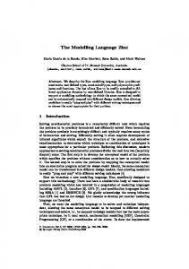
This section provides a small example of how our analysis method can be used in practice to locate interactions. Given the FORML model in Figures 1 and 2, the translator can be run to generate an Alloy model. When this Alloy model is loaded into the Alloy IDE, the user has several options for checking the various assertions. For that model in particular, there are 13 assertions created that will check pairs of transitions to see if they interact. First a user will need to determine and specify the maximum number of distinct and valid world states. This is done by guessing the exact number of world states and running the Alloy model using the distinct_valid_WSs predicate. If instances are found, then the number is either too low, or correct. If instances are not found, then the number is too high. A binary search can be performed in this way to find the maximum number of world states (i.e., the number i that generates instances where the number i + 1 does not generate instances). A partial instance can now be created using our partial-instance translator. Once the user includes this partial instance with their Alloy file, they are ready to check the assertions efficiently to identify interactions. When the analyzer completes its checking of the 13 assertions, the user will see that one of the assertions returned a counter-example; this means that there is a potential interaction. In this case, the interaction is between transitions t3 and t4 (see Figure 2). It is relatively straightforward to reason out why this particular interaction occurs; both transitions are trying to change the AutoSoftCar_acceleration value. However, an interaction could be much more complex. In complex cases, the user should open the Alloy visualizer to view the exact world state which leads to the interaction occurring. The user would see something similar to what is shown in Figure 15. This figure shows part of the initial state for the world where the interaction occurs (the world contains more concepts, but they are not shown). In the visualized output, the AutoSoftCar object has two variable names listed on it: $AutoSoftCar_t3 and $AutoSoftCar_t4; these indicate that this AutoSoftCar is being acted on by transitions t3 and t4. The current value of the AutoSoftCar’s acceleration attribute is 1. The other important part of the output are the two integers 0 and -2, which are labelled with the variable names $change_t4 and $change_t3, respectively. In this way, the visualizer will mark the exact objects in the world that are being acted on by transitions. By using the knowledge that transitions t3 and t4 are changing the AutoSoftCar’s acceleration, the output can be read as: transition t3 is changing an AutoSoftCar’s acceleration value to -2, and transition 22
Figure 15: The initial world state for a counter-example where two transitions are each trying to change the acceleration attribute on an AutoSoftCar. This visualization uses a custom Alloy theme. t4 is changing an AutoSoftCar’s acceleration value to 0. Clearly, the interaction is occurring because the acceleration is being changed to two different values. This kind of information is given whenever there is an interaction; using this the user can reason out the circumstances that are leading to the interaction. With this information the user can return to their original FORML model and resolve the interaction. In this case, adding a transition priority, saying that t4 always takes precedence over t3 (e.g., t4 > t3), resolves the interaction. Much of the output that is given by the visualizer may not directly relate to the interaction (as the counter-example shows the entire world state). For instance, for the AutoSoftCar object in Figure 15, the arguments: AutoSoftCars, PhysicalObjects and RoadObjects state that an AutoSoftCar is a part of those three sets of objects (due to the inheritance relations in the world model). This information may still be useful when attempting to determine the cause of an interaction.
8
Limitations
There are a few limitations of the translator that a user should be aware of when translating FORML models into Alloy. One limitation is that triggers and guards on transitions are not translated into Alloy. This can lead to false positives, in that the analyzer will report that two transitions interact when in fact they never execute concurrently because their triggers or guard conditions are incompatible. Unfortunately, it is impossible to detect which transitions can execute concurrently: this would require a reachability analysis of the FORML behaviour model. A second limitation is that the translator does not attempt to detect and resolve name 23
conflicts. For example, the sets of concepts in a world state are named by making the concept names plural (e.g., a type T will have a set Ts in the world state). This strategy will cause a naming conflict if there is another type that is named Ts. The translator will not report any kind of warning or error when this occurs. The resulting Alloy model will be incorrect and will probably throw compilation errors when it is executed. The possible naming conflicts are: • Having a concept with name T, and another concept with name Ts. • Different concepts with the same name (e.g., a model in which both a message and a feature is named X). • Conflicting enumeration definitions • Conflicting macro definitions Lastly, the translator does not perform any kind of error checking. If the input model is missing elements or is otherwise incorrect, the translator will not detect any problems or report any errors.
9
Conclusion
In this report, we present a translator that translates a FORML model into Alloy. In addition, the translator automatically generates assertions that, using the Alloy analyzer, will detect interactions between concurrently executing transitions. We have shown that this method can be used on partial FORML models, and that it can be implemented efficiently. This approach has the benefit that it requires very little interaction with a user and can be used with no specific background knowledge of model verification.
References [1] UML Specification, 2007. [2] Object Constraint Language Specification, 2010. [3] Sven Apel and Christian Kastner. An overview of feature-oriented software development. Journal of Object Technology, 2009. [4] Jonas Barklund and Johan Bevemyr. Prolog with arrays and bounded quantifications. Logic Programming and Automated Reasoning, 1993. [5] Daniel Jackson. Alloy: a lightweight object modelling notation. TOSEM, pages 256 – 290, 2002. [6] A.J. Malton K.A. Schneider J.R. Cordy, T.R. Dean. Source transformation in software engineering using the TXL transformation system. Journal of Information and Software Technology, 1985. 24
[7] G. Georg K. Anastasakis, B. Bordbar and I. Ray. On challenges of model transformation from UML to Alloy. Software System Models, 2010. [8] Vajih Montaghami and Derek Rayside. Extending alloy with partial instances. In To be presented at ABZ 2012, 2012. [9] Oracle. Getting starting with UML class modeling. Technical report, Oracle, 2007. [10] Pourya Shaker and Joanne M Atlee. Feature-oriented requirements modelling language (FORML). Technical report, University of Waterloo, 2011. [11] Salvador Trujillo Sven Apel, Florian Janda and Christian Kastner. Model superimposition in software product lines. In Proceedings of the International Conference on Model Transformation, 2009.
25
A
FORML Grammar
The complete FORML plain text grammar has been provided below. This grammar corresponds to the FORML metamodel. The state machine provided should be a composite state machine in which all possible features in the SPL have been composed into one large state machine. The grammar for the TXL program is not identical to this, but is equivalent. % world model world−model := c o n c e p t ∗ p r e d i c a t e ∗ macro ∗ c o n c e p t := b a s i c −c o n c e p t ∗ a s s o c i a t i o n ∗ p a r t o f −a s s o c i a t i o n ∗ message ∗ SPL∗ f e a t u r e ∗ enumeration ∗ b a s i c −c o n c e p t := ( ' a b s t r a c t ' ) ? ' concept ' ID ( ' extends ' ID ) ? a t t r i b u t e ∗ a t t r i b u t e := ' a t t r i b u t e ' d e c l d e c l := ID ' [ ' m u l t i p l i c i t y ' ] ' ' : ' ID m u l t i p l i c i t y := (NAT | ' ∗ ' ) | (NAT ' . . ' (NAT | ' ∗ ' ) ) id− l i s t := ID ( ' , ' ID ) ∗ a s s o c i a t i o n := ( ' a b s t r a c t ' ) ? ' a s s o c i a t i o n ' ID ( ' extends ' id− l i s t ) ? a t t r i b u t e ∗ role {2..∗} r o l e := ' r o l e ' ID ' [ ' m u l t i p l i c i t y ' ] ' ' : ' ID p a r t o f −a s s o c i a t i o n := ( ' a g g r e g a t i o n ' | ' c o m p o s i t i o n ' ) ID a t t r i b u t e ∗ ' whole ' r o l e ' part ' r o l e message := ( ' a b s t r a c t ' ) ? ' message ' ID ( ' extends ' ID ) ? a t t r i b u t e ∗ SPL := 'SPL ' ID a t t r i b u t e ∗ f e a t u r e ∗ f e a t u r e := ' f e a t u r e ' ID ' [ ' f e a t u r e C a r d i n a l i t y ' ] ' ' { ' a t t r i b u t e ∗ ( ' i n p u t s ' id− l i s t ) ? ( ' outputs ' id− l i s t ) ? f e a t u r e ∗ ' } ' c a r d i n a l i t y := (NAT ' . . ' (NAT | ' ∗ ' ) ) f e a t u r e C a r d i n a l i t y := ( ' 0 . . 1 ' | ' 1 ' ) enumeration := ' enum ' ID '= { ' id− l i s t ' } ' macro := ' l e t ' ID '= ' expr % expressions expr := s e t −expr | p r e d i c a t e s e t −expr := ' ( ' ? atomic | d e r i v e d | u n s p e c i f i e d ' ) ' ? atomic := ' none ' | ID | id−r e f | ID ' s ' ' @pre ' ? d e r i v e d := n a v i g a t i o n | standard −s e t −op | s e l e c t i o n | c o n d i t i o n a l | i n t e g e r n a v i g a t i o n := ( s e t −expr ' . ' ) ? ( ID | ID ' − ' ID | ' to ' | ' from ' ) ' @pre ' ? standard −s e t −op := s e t −expr ( '+ ' | '\& ' | ' − ') s e l e c t i o n := s e t −expr ' [ ' ID | p r e d i c a t e ' ] ' c o n d i t i o n a l := ' i f ' p r e d i c a t e ' then ' s e t −expr ' e l s e ' s e t −expr i n t e g e r := '# ' s e t −expr | i n t e g e r ( '+ ' | ' − ') i n t e g e r u n s p e c i f i e d := ( f u n c t i o n −c a l l | ID ' { ' f u n c t i o n −c a l l ' } ' ) ' @pre ' ? f u n c t i o n −c a l l := ID ' ( ) ' p r e d i c a t e := ' ( ' ? standard −s e t −pred | standard −l o g i c −pred | c a r d i n a l i t y −pred | q u a n t i f i e d −pred | i n t e g e r −pred | u n s p e c i f i e d ' ) ' ? standard −s e t −pred := s e t −expr ( '= ' | ' in ' ) s e t −expr standard −l o g i c −pred := ' not ' p r e d i c a t e | p r e d i c a t e ( ' and ' | ' or ' | ' i m p l i e s ' | ' i f f ') predicate c a r d i n a l i t y −pred := ( ' no ' | ' l o n e ' | ' one ' | ' some ' ) s e t −expr q u a n t i f i e d −pred := ( ' no ' | ' l o n e ' | ' one ' | ' some ' | ' a l l ' ) vars −d e c l ( ' , ' vars − decl ) ∗ '\ textbar ' p r e d i c a t e
26
vars −d e c l := ' d i s j ' ? id− l i s t ' : ' ID i n t e g e r −pred := i n t e g e r ( '= ' | ' > ' | ' < ' | '== ') i n t e g e r % c o m p o s i t e b e h a v i o u r model ( i n p u t t o a n a l y z e r ) beh avio ur −model := 'SPL ' ID s t a t e −machine ∗ s t a t e −machine := ' s t a t e −machine ' id−r e f i n i t −s t a t e s t a t e ∗ t r a n s i t i o n ∗ bm−macro ∗ s t a t e := ' s t a t e ' id−r e f r e g i o n ∗ r e g i o n := ' r e g i o n ' id−r e f i n i t −s t a t e ? s t a t e ∗ i n i t −s t a t e := ' i n i t =' id−r e f t r a n s i t i o n := ' t r a n s i t i o n ' id−r e f tran−p r i o r i t y ? ' : ' ext−id−r e f '−>' ext−id−r e f t r i g ? guard ? ( ' / ' WCA− l i s t ) ? tran−p r i o r i t y := ' > ' id−r e f t r i g := o v e r r i d e | ' when ( ' id−r e f ' ) ' | ' a f t e r ( ' ID ' ) ' | WCE o v e r r i d e := ' o v e r r i d e ( ' id−r e f ' ) ' WCE := ID '+( o ) ' | ID ' ( ' id− l i s t ? ' ) ' | ID ' −( o ) ' | s e t −expr ' − ' | ID ' . ' ID ' ~ ( o ) ' | s e t −expr ' . ' ID ' ~ ' guard := ' [ ' p r e d i c a t e ' ] ' WCA− l i s t := WCA ( ' , ' WCA) ∗ WCA := ID ' : ' o v e r r i d e ? guard ? ( ( id−r e f '= ') ? '+ ' ID ' ( ' a s s i g n − l i s t ' ) ' | ' ! ' ID ' ( ' a s s i g n − l i s t ' ) ' | ' − ' s e t −expr | s e t −expr ' . ' ID ' : = ' s e t −expr ) a s s i g n − l i s t := ( ID ' : : ' ) ? ID '= ' s e t −expr ( ' , ' ( ID ' : : ' ) ? ID '= ' s e t −expr ) ∗ bm−macro := l e t id−r e f '= ' expr id−r e f := ID ' { ' ID ' } ' ext−id−r e f := ID ' { ' ID ( ' . ' ID ) ∗ ' } ' ( ' . ' ID ' { ' ID ( ' . ' ID ) ∗ ' } ' ) ?
27
B
Textual FORML Model of the BDS Example
This section provides a more in-depth example of how the FORML graphical syntax corresponds to the textual syntax. Figures 16 and 17 give a small example of a FORML model of only a single feature, the Basic Driving Service (BDS). Following the figures is the corresponding textual representation of the model.
Figure 16: A World Model with a single feature
Figure 17: A Behaviour Model for the Basic Driving Service corresponding to the above World Model
28
%These a r e t h e l i s t o f c o n c e p t s i n t h e model abstract concept PhysicalObject a t t r i b u t e p o s i t i o n [ 1 ] : Coord a t t r i b u t e shape [ 1 ] : Shape c o n c e p t Lane e x t e n d s P h y s i c a l O b j e c t c o n c e p t RoadSegment e x t e n d s P h y s i c a l O b j e c t a t t r i b u t e speedLimit [ 1 ] : Int c o n c e p t RoadObject e x t e n d s P h y s i c a l O b j e c t a t t r i b u t e speed [ 1 ] : Int attribute acceleration [ 1 ] : Int attribute orientation [ 1 ] : Int attribute direction [ 1 ] : Direction c o n c e p t AutoSoftCar e x t e n d s RoadObject attribute ignition [1] : IgnitionState concept Driver %A l l o f t h e c o m p o s i t i o n s and a g g r e g a t i o n s i n t h e model a s s o c i a t i o n IsOn r o l e roadSeg [ 1 ] : RoadSegment r o l e roadObj [ ∗ ] : RoadObject aggregation Drives whole r o l e r 1 [ 1 ] : AutoSoftCar part r o l e r2 [ 1 ] : Driver c o m p o s i t i o n LaneOnRoadSeg whole r o l e r 1 [ 1 ] : RoadSegment p a r t r o l e r 2 [ 1 . . ∗ ] : Lane composition Contains whole r o l e r 1 [ 1 ] : AutoSoftCar p a r t r o l e r 2 [ 1 ] : AutoSoft %The SPL and f e a t u r e model SPL AutoSoft f e a t u r e BDS [ 1 ] { i n p u t s IgniteOn , I g n i t e O f f , S t e e r , A c c e l e r a t e , D e c e l e r a t e } %The mes sages t h a t can be used by t h e f e a t u r e s message I g n i t e O n input message I g n i t e O f f input message S t e e r input a t t r i b u t e value [ 1 ] : Int message A c c e l e r a t e input a t t r i b u t e value [ 1 ] : Int message D e c e l e r a t e input a t t r i b u t e value [ 1 ] : Int %Enumerations used i n t h e model %I t i s a l s o p o s s i b l e t o have u n d e f i n e d types , s o do not need e n u m e r a t i o n s f o r
29
everything enum I g n i t i o n S t a t e = {on , o f f } %The b e h a v i o u r model SPL AutoSoft s t a t e −machine BDS{main} i n i t = BDS{ o f f } s t a t e BDS{ o f f } s t a t e BDS{on} r e g i o n BDS{ a c c e l e r a t i o n } i n i t = BDS{ w a i t A c c e l e r a t e } s t a t e BDS{ w a i t A c c e l e r a t e } r e g i o n BDS{ d e c e l e r a t i o n } i n i t = BDS{ w a i t D e c e l e r a t e } s t a t e BDS{ w a i t D e c e l e r a t e } r e g i o n BDS{ s t e e r i n g } i n i t = BDS{ w a i t S t e e r } s t a t e BDS{ w a i t S t e e r } t r a n s i t i o n BDS{ t 1 } : BDS{ o f f } −> BDS{on} I g n i t e O n ( ) / BDS{ a1 } : AutoSoftCar . i g n i t i o n := on t r a n s i t i o n BDS{ t 2 } : BDS{on} −> BDS{ o f f } I g n i t e O f f ( ) / BDS{ a1 } : AutoSoftCar . i g n i t i o n := o f f t r a n s i t i o n BDS{ t 3 } : BDS{on . a c c e l e r a t i o n . w a i t A c c e l e r a t e } −> BDS{on . acceleration . waitAccelerate } A c c e l e r a t e ( v a l u e ) / BDS{ a1 } : AutoSoftCar . a c c e l e r a t i o n := BDS{ a c c e l e r a t i o n () } t r a n s i t i o n BDS{ t 4 } : BDS{on . d e c e l e r a t i o n . w a i t D e c e l e r a t e } −> BDS{on . deceleration . waitDecelerate } D e c e l e r a t e ( v a l u e ) / BDS{ a1 } : AutoSoftCar . a c c e l e r a t i o n := BDS{ d e c e l e r a t i o n () } t r a n s i t i o n BDS{ t 5 } : BDS{on . s t e e r i n g . w a i t S t e e r } −> BDS{on . s t e e r i n g . w a i t S t e e r } S t e e r ( v a l u e ) / BDS{ a1 } : AutoSoftCar . o r i e n t a t i o n := BDS{ s t e e r ( ) }
The translated Alloy output is too large to put in the report (this is due to the size of the assertions and the generated names for objects). This exact example can be found in the code provided with the report, in the file input2.form.
30
C
FORML to Alloy Translation Rules
This appendix contains the general rules for the translation from FORML to Alloy.
C.1
World Model to Alloy
A world model wm is translated to an Alloy model 〚wm〛 of the form: 1 2 3 4 5 6 7 8 9 10
[type signatures] sig WS { [WS fields] } pred WSC (ws: WS) { [WSC constraints] } pred WSTC (wsPre, wsPost: WS) { [WSTC constraints] }
where • The place-holder [type signatures] (line 1) stands for a set of signatures, each of which specifies a type (a concept, an enumeration, or an undefined type) in wm. • The signature WS (lines 2-4) specifies the world-state space of wm. The place-holder [WS fields] (line 3) stands for a set of fields of WS that specify the elements of a world state. • The predicate WSC (lines 5-7) specifies constraints on possible world states. The placeholder [WSC constraints] (line 6) stands for a set of Alloy constraints over a world-state ws. • The predicate WSTC (lines 8-10) specifies constraints on possible world-state transitions. The place-holder [WSTC constraints] (line 9) stands for a set of Alloy constraints over two consecutive before (wsPre) and after (wsPost) world states. The following subsections describe how the above place holders are populated through translating the types and constraints in wm. C.1.1
Undefined Types
An undefined type T is translated to a type signature 1
sig T {}
C.1.2
Enumerations
A FORMoL enumeration, which is expressed as an Alloy enumeration, is simply repeated as a type signature. 31
C.1.3
Concepts
A concept A is at least translated to the following place-holder elements: • A type signature, which in the simplest case, is sig A {}
If A is abstract, so is its type signature: abstract A {}
If A is a subtype of a concept B, its type signature extends that of B: sig A extends B {}
• A WS field As: set A
which represents the set of objects of type A in a world state • For each attribute a with type T of A, a WS field A_a: As -> T
which specifies the value of a for each A object in a world state; and a WSC constraint that specifies a’s multiplicity, provided that the multiplicity is not ∗: for a multiplicity of n, the WSC constraint is all o: ws.As | #o.(ws.A_a) = n
for a multiplicity of n..∗, the WSC constraint is all o: ws.As | #o.(ws.A_a) >= n
and for a multiplicity of n1..n2, the WSC constraint is all o: ws.As | #o.(ws.A_a) >= n1 and #o.(ws.A_a) =< n2
• If A is abstract and has subtypes B1...Bn, a WSC constraint ws.As = ws.B1s + ... + ws.Bns
32
which specifies that there are no A objects in a world state, besides those of its subtypes • If A is a subtype of concept B, a WSC constraint ws.As = ws.Bs & A
which specifies that any A object in a world state is also a B object in the world state
C.1.3.1
Associations
An association A is additionally translated to the following place-holder elements: • For each role r with type T of A, a WS field A_r: As ->one Ts
which specifies the object in role r of each A link (object) in a world state; and a WSC constraint that specifies r’s multiplicity, provided that the multiplicity is not ∗: given that in addition to r, A has roles r1...rn with types T 1...T n, for a multiplicity of n, the WSC constraint is all o1: ws.T1s, ..., on: ws.Tns | #((ws.A_r1.o1 & ... & ws.A_rn.on).(ws.A_r)) = n
for a multiplicity of n..∗, the WSC constraint is all o1: ws.T1s, ..., on: ws.Tns | #((ws.A_r1.o1 & ... & ws.A_rn.on).(ws.A_r)) >= n
for a multiplicity of n1..n2, the WSC constraint is all o1: ws.T1s, ..., on: ws.Tns | #((ws.A_r1.o1 & ... & ws.A_rn.on).(ws.A_r)) >= n1 and #((ws.A_r1.o1 & ... & ws.A_rn.on).(ws.A_r)) =< n2
• For each role r of A, a WSTC constraint all o: wsPre.As & wsPost.As | o.(wsPre.A_r) = o.(wsPost.A_r)
which specifies that the objects related by a link do not change over time
33
C.1.3.2
Aggregations and Compositions
An aggregation or composition A whose whole-role w and part-role p are both of type T is additionally translated to a WSC constraint all o: ws.As | not o.(ws.A_w) = o.(ws.A_p)
which specifies that an object cannot be part of itself. A composition B with a part-role p of type T and a whole-role w is additionally translated to a WSTC constraint all o: wsPre.Ts & wsPost.Ts | wsPre.B_p.o.(wsPre.B_w) = wsPost.B_p.o.(wsPost.B_w)
which specifies that a part object is ever in a composition link with a single whole object. C.1.3.3
Features
In a world model for SPL S, a feature concept A is additionally translated to the following place-holder elements: • A WS field that specifies the A feature (if any) of each S product in a world state. If A is mandatory, the WS field is S_A: Ss one->one As
and if A is optional, the WS field is S_A: Ss one->lone As
• If A is optional and has a parent feature concept B, a WSC constraint all o: ws.Ss | one o.(ws.S_A) implies one o.(ws.S_B)
which specifies that an optional feature can be present in a product only if its parent feature is present in the product • A WSTC constraint wsPre.S_A = wsPost.S_A
which specifies that the feature configuration of each SPL product in a world state is fixed.
34
C.1.3.4
Messages
In a world model for SPL S, a message A is additionally translated to the following placeholder elements: • If A is an input message, a WS field A_to: As ->one Ss
which specifies the S product that each A message object is sent to in a world state; and if A is an output message, a WS field A_from: As ->one Ss
which specifies the S product that each A message object is sent by in a world state • A WSTC constraint no (wsPre.As & wsPost.As)
which specifies that message objects are transient C.1.4
Constraints
A world-state constraint (world-state transition constraint) is translated to a WSC constraint (WSTC constraint) using the rules for translating world-model expressions to Alloy, which are presented in Section C.2.
C.2
World-Model Expressions to Alloy
A FORMoL-expression expr over a world-model wm is translated to an Alloy-constraint 〚expr〛 over the Alloy-model 〚wm〛. The following subsections give the translation rules for the different types of FORMoL expressions. C.2.1
Parenthesized Expressions
Where expr is an abitrary FORMoL expression, 〚(expr)〛 = (〚expr〛)
35
C.2.2 C.2.2.5
Set Expressions Atomic Expressions
Where v is a variable, T is a type, and A is a concept, 〚none〛 = none 〚v〛 = v 〚T 〛 = T 〚As〛 = ws.As
C.2.2.6
Navigation Expressions
In the following rules, set is a FORMoL set expression that evaluates to a set of objects of concept A. Where x is an attribute of A, or A is an association and x is a role of A, or A is an SPL and x is a feature of A, 〚set.x〛 = 〚set〛.A_x
Where A is a message, 〚set.to〛 = 〚set〛.A_to 〚set.f rom〛 = 〚set〛.A_from
Where B is an association with a role r of type A, 〚set.B − r〛 = B_r.〚set〛
Where B is an association with only one role of type A, 〚set.B〛 = B_r.〚set〛
C.2.2.7
Set Operations
Where set , set1 , and set2 are FORMoL set expressions, and pred is a FORMoL predicate, 〚set1 + set2〛 = 〚set1〛 + 〚set2〛 〚set1 − set2〛 = 〚set1〛 - 〚set2〛 〚set1 & set2〛 = 〚set1〛 & 〚set2〛 〚if pred then set1 else set2〛 = if 〚pred〛 then 〚set1〛 else 〚set2〛 〚set[o | pred]〛 = {o: 〚set〛 | 〚pred〛}
36
C.2.3
Integer Expressions
Where number is an integer, set is a FORMoL set expression, and int1 and int2 are FORMoL integer expressions, 〚number〛 = number 〚#set〛 = #〚set〛 〚int1 + int2〛 = 〚int1〛 + 〚int2〛 〚int1 − int2〛 = 〚int1〛 - 〚int2〛
C.2.4
Predicates
C.2.4.8
Set Operations
Where set , set1 , and set2 are FORMoL set expressions, 〚set1 = set2〛 = 〚set1〛 = 〚set2〛 〚set1 in set2〛 = 〚set1〛 in 〚set2〛 〚no set〛 = no 〚set〛 〚lone set〛 = lone 〚set〛 〚one set〛 = one 〚set〛 〚some set〛 = some 〚set〛
C.2.4.9
Logic Operations
Where pred , pred1 , and pred2 are FORMoL predicates, 〚not pred〛 = not 〚pred〛 〚pred1 and pred2〛 = 〚pred1〛 and 〚pred2〛 〚pred1 or pred2〛 = 〚pred1〛 or 〚pred2〛 〚pred1 implies pred2〛 = 〚pred1〛 implies 〚pred2〛 〚pred1 if f pred2〛 = 〚pred1〛 iff 〚pred2〛
C.2.4.10
Quantification Predicates
Where set is a FORMoL set expression and pred is a FORMoL predicate, 〚no v : set | pred〛 = no v: 〚set〛 | 〚pred〛 〚lone v : set | pred〛 = lone v: 〚set〛 | 〚pred〛 〚one v : set | pred〛 = one v: 〚set〛 | 〚pred〛 〚some v : set | pred〛 = some v: 〚set〛 | 〚pred〛 〚all v : set | pred〛 = all v: 〚set〛 | 〚pred〛
37
Quantification predicates that involve multiple variables and the keyword disj are similarly translated. For example, 〚all disj v1, v2 : set1, v3 : set2 | pred〛 = all disj v1, v2: 〚set1〛, v3: 〚set2〛 | 〚pred〛
C.2.4.11
Integer Predicates
Where int1 and int2 are FORMoL integer expressions, 〚int1 〚int1 〚int1 〚int1 〚int1 〚int1
C.2.5
= int2〛 = 〚int1〛 = 〚int2〛 int2〛 = not 〚int1〛 = 〚int2〛 > int2〛 = 〚int1〛 > 〚int2〛 < int2〛 = 〚int1〛 < 〚int2〛 = 〚int2〛
@pre
Where expr is an arbitrary FORMoL expression, 〚expr@pre〛 = 〚expr〛[wsPre/ws]
In the above rule, 〚expr〛[wsPre/ws] is the result of replacing all occurences of ws with wsPre in 〚expr〛.
C.3
WCA Types to Alloy
A WCA-type wca of a world-model wm is translated to an Alloy predicate 〚wca〛 over the Alloy-model 〚wm〛 that specifies the WCA’s postcondition, excluding frame conditions. The following subsections give the translation rules for the different types of WCAs. C.3.1
Create Object
A WCA-type for creating an object of concept A is translated to a predicate of the form 1 2 3 4
pred addA(wsPost: WS, o: A, [parameters]) { o in wsPost.As [postconditions] }
where • The parameter wsPost (line 1) represents the world-state after the WCA is performed 38
• The parameter o (line 1) represents the newly added A object • The postcondition o in wsPost.As (line 2) specifies that o is in wsPost • The placeholder [parameters] (line 1) stands for a set of parameters, each of which represents a value (i.e., a set of one or more instances of a type in wm) related to o • The placeholder [postconditions] (line 3) stands for a set of postconditions that specify how o is related to the values represented by the above parameters The following subsections describe how the above place holders are populated for different types of values related to A objects. C.3.1.12
Attributes
Each attribute a with type T of A adds a parameter a_val: set T
and a postcondition o.(wsPost.A_a) = a_val
or if a is inherited from a concept B, a postcondition o.(wsPost.B_a) = a_val
which specify that o’s a attribute has value a_val in wsPost. C.3.1.13
Association Roles
If A is an association, each role r with type T of A adds a parameter r_val: T
and a postcondition o.(wsPost.A_r) = r_val
or if r is inherited from an association B, a postcondition o.(wsPost.B_r) = r_val
39
which specify that in wsPost, o relates object r_val in role r. C.3.1.14
Message Parameters with Concept Types
If A is a message, each message-parameter p of A whose type is a concept C adds a parameter p_val: set A_p one->one C
(where A_p is the aggregation representing p, that is between A in role msg and C in role val ) and the postconditions p_val.C in wsPost.A_ps (p_val.C)->o in wsPost.A_p_msg p_val in wsPost.A_p_val
or if p is inherited from a message B, the postconditions p_val.C in wsPost.B_ps (p_val.C)->o in wsPost.B_p_msg p_val in wsPost.B_p_val
which specify that o’s p parameter has value A_p.p_val or B_p.p_val in wsPost. C.3.2
Remove Objects
A WCA-type for removing a set of objects of a concept A is translated to the predicate pred removeA(wsPost: WS, O: set A) { not O in wsPost.As }
which specifies that the removed A-objects O are not present in the world-state wsPost following the WCA. C.3.3
Change Attribute Value
A WCA-type for changing the value of an attribute a with type T of an object of a concept A is translated to the predicate pred changeA_a(wsPost: WS, o: A, val: set T) { o.(wsPost.A_a) = val }
which specifies that attribute a of the A-object o has value val in the world-state wsPost following the WCA. 40
C.4
Assertions
Given a FORMoL model with a world model wm and a behaviour model bm, each pair of concurrent transitions in bm is translated into an Alloy assertion over the Alloy-model 〚wm〛. Such assertions are run over the space of all valid world states that can be constructed from a chosen number of instances of each type in wm. This space can be characterized as the largest world-state space that satisfies the predicate 1 2 3 4
pred distinct_valid_WSs { all ws, ws': WS | ws = ws' iff ws.F1 = ws'.F1 and ... and ws.Fn = ws'.Fm all ws: WS | WSC[ws] }
given that the number of instances of each wm type respects the chosen bound. The above predicate constrains the generated world-state space to containing distinct (line 2) and valid (line 3) world states, where F1 ... Fm are the WS fields of 〚wm〛. The assertion for a pair of transitions with a combined set of concurrent WCAs named id1 ... idn is of the form 1 2 3 4 5 6 7
assert id1_..._idn { distinct_valid_WSs implies all wsPre: WS | all [WCA arguments] | some wsPost: {ws: WS - wsPre | WSTC[wsPre, ws]} | [WCA invocations] }
The assertion states that within the generated world-state space (line 2 together with the bounds specified in the check command described below), starting from any world-state wsPre (line 3), and for all combinations of arguments supplied to the WCAs (line 4), there exists a world-state wsPost that can be arrived at by performing the WCAs; that is, the transition from wsPre to wsPost satisfies the world-state transition constraints in wm (line 5), and wsPost satisfies the postconditions of all of the WCAs (line 6). The place-holder [WCA arguments] (line 4) stands for a comma-separated set of Alloy declarations, each of which specifies the possible arguments that can be supplied for a particular parameter of a particular WCA. The place-holder [WCA invocations] (line 6) stands for the conjunction, via the Alloy-operator and, of a set of Alloy-predicate invocations, each of which specifies a particular WCA. Each WCA id of type wca adds the following place-holder elements: • A WCA invocation that is the invocation of the Alloy predicate 〚wca〛 using the WCA arguments below. • Each parameter of 〚wca〛 adds a WCA argument: – If id creates an A object, parameter o: A of 〚wca〛 adds a WCA argument id_o: A - wsPre.As
41
and each parameter a_val: set T of 〚wca〛 adds a WCA argument id_a_val: set T
If A is an association, each parameter r_val: T of 〚wca〛 adds a WCA argument id_r_val: T
If A is a message, each parameter p_val: set A_p one->one C of 〚wca〛 adds a WCA argument id_p_val: set (A_p - wsPre.A_ps) one->one wsPre.Cs
– If id removes a set of A objects, parameter O: set A of 〚wca〛 adds a WCA argument id_O: set wsPre.As
– If id changes an attribute value of an A object, parameter o: A of 〚wca〛 adds a WCA argument id_o: wsPre.As
and parameter val: set T of 〚wca〛 adds a WCA argument id_val: set T
The assertion above can be run using the Alloy command check id1_..._idn for exactly x1 T1, ..., exactly xn Tn, exactly y WS
where T1 ... Tn are the types in wm, x1 ... xn are the chosen number of instances for these types, and y is the size of the largest world-state space satisfying the predicate distinct_valid_WSs that can be constructed using the chosen bounds.
42
D
Partial Generated Alloy Model of the BDS Example
This section contains a partial model of the BDS example in Appendix B. The entire translation of the World model, and a partial list of the generated WCAs and assertions is included. There is a small difference between the model here and what is described elsewhere in the report: the WCAs check both the pre- and post-condition of its action. As a result, the assertions have also changed slightly. On line three of each assertion, when the transition arguments are gathered, the type of each assertion is just the type of the object for the action (instead of the more complex types in Appendix C). There is no change in behaviour using this method; this is done to ease the translator implementation so that the assertion generation logic does not need to know what types of actions are used in the transitions. 1 2 3 4 5 6 7 8 9 10 11 12 13 14 15 16 17 18 19 20 21 22 23 24 25 26 27 28 29 30 31 32 33 34 35 36 37 38 39
a b s t r a c t s i g P h y s i c a l O b j e c t {} s i g D r i v e r {} s i g Lane e x t e n d s P h y s i c a l O b j e c t {} s i g RoadSegment e x t e n d s P h y s i c a l O b j e c t {} s i g RoadObject e x t e n d s P h y s i c a l O b j e c t {} s i g AutoSoftCar e x t e n d s RoadObject {} s i g IsOn {} s i g D r i v e s {} s i g LaneOnRoadSeg {} s i g C o n t a i n s {} s i g AutoSoft {} s i g BDS {} s i g I g n i t e O n {} s i g I g n i t e O f f {} s i g S t e e r {} s i g A c c e l e r a t e {} s i g D e c e l e r a t e {} s i g Shape {} s i g Coord {} s i g D i r e c t i o n {} enum Bool { t r u e , f a l s e } enum I g n i t i o n S t a t e {on , o f f } s i g WS { PhysicalObjects : set PhysicalObject , Drivers : s e t Driver , Lanes : s e t Lane , RoadSegments : s e t RoadSegment , RoadObjects : s e t RoadObject , AutoSoftCars : s e t AutoSoftCar , IsOns : s e t IsOn , Drivess : s e t Drives , LaneOnRoadSegs : s e t LaneOnRoadSeg , C o n t a i n s s : s e t Contains , A u t o S o f t s : s e t AutoSoft , BDSs : s e t BDS, I g n i t e O n s : s e t IgniteOn , IgniteOffs : set IgniteOff ,
43
40 41 42 43 44 45 46 47 48 49 50 51 52 53 54 55 56 57 58 59 60 61 62 63 64 65 66 67 68 69 70 71 72 73 74 75 76 77 78 79 80 81 82 83 84 85 86 87 88 89 90
} {
}
Steers : set Steer , Accelerates : set Accelerate , Decelerates : set Decelerate , P h y s i c a l O b j e c t _ s h a p e : P h y s i c a l O b j e c t s −> Shape , P h y s i c a l O b j e c t _ p o s i t i o n : P h y s i c a l O b j e c t s −> Coord , RoadSegment_speedLimit : RoadSegments−> Int , R o a d O b j e c t _ d i r e c t i o n : RoadObjects−> D i r e c t i o n , R o a d O b j e c t _ o r i e n t a t i o n : RoadObjects−> Int , R o a d O b j e c t _ a c c e l e r a t i o n : RoadObjects−> Int , RoadObject_speed : RoadObjects−> Int , A u t o S o f t C a r _ i g n i t i o n : AutoSoftCars−> I g n i t i o n S t a t e , IsOn_roadSeg : IsOns−> one RoadSegments , IsOn_roadObj : IsOns−> one RoadObjects , Drives_r1 : D r i v e s s −> one AutoSoftCars , Drives_r2 : D r i v e s s −> one D r i v e r s , LaneOnRoadSeg_r1 : LaneOnRoadSegs−> one RoadSegments , LaneOnRoadSeg_r2 : LaneOnRoadSegs−> one Lanes , Contains_r1 : C o n t a i n s s −> one AutoSoftCars , Contains_r2 : C o n t a i n s s −> one AutoSofts , AutoSoft_BDS : A u t o S o f t s one−>one BDSs , IgniteOn_to : I g n i t e O n s −> one AutoSofts , I g n i t e O f f _ t o : I g n i t e O f f s −> one AutoSofts , S t e e r _ v a l u e : S t e e r s −> Int , S t e e r _ t o : S t e e r s −> one AutoSofts , A c c e l e r a t e _ v a l u e : A c c e l e r a t e s −> Int , A c c e l e r a t e _ t o : A c c e l e r a t e s −> one AutoSofts , D e c e l e r a t e _ v a l u e : D e c e l e r a t e s −> Int , D e c e l e r a t e _ t o : D e c e l e r a t e s −> one AutoSofts , all all all all all all all all all all all
o o o o o o o o o o o
: : : : : : : : : : :
PhysicalObjects | # (o . PhysicalObject_position ) = 1 PhysicalObjects | # ( o . PhysicalObject_shape ) = 1 RoadSegments | # ( o . RoadSegment_speedLimit ) = 1 RoadObjects | # ( o . RoadObject_speed ) = 1 RoadObjects | # ( o . R o a d O b j e c t _ a c c e l e r a t i o n ) = 1 RoadObjects | # ( o . R o a d O b j e c t _ o r i e n t a t i o n ) = 1 RoadObjects | # ( o . R o a d O b j e c t _ d i r e c t i o n ) = 1 AutoSoftCars | # ( o . A u t o S o f t C a r _ i g n i t i o n ) = 1 S t e e r s | # ( o . Steer_value ) = 1 Accelerates | # ( o . Accelerate_value ) = 1 Decelerates | # ( o . Decelerate_value ) = 1
pred WSC ( ws : WS) { ( ws . Lanes = ws . P h y s i c a l O b j e c t s & Lane ) ( ws . RoadSegments = ws . P h y s i c a l O b j e c t s & RoadSegment ) ( ws . RoadObjects = ws . P h y s i c a l O b j e c t s & RoadObject ) ( ws . AutoSoftCars = ws . RoadObjects & AutoSoftCar ) ( a l l r o a d o b j e c t : ws . RoadObjects | # ( ( ( ( ws . IsOn_roadObj ) . r o a d o b j e c t ) ) . ( ws . IsOn_roadSeg ) ) = 1 ) ( a l l d r i v e r : ws . D r i v e r s | # ( ( ( ( ws . Drives_r2 ) . d r i v e r ) ) . ( ws . Drives_r1 ) ) = 1 ) ( a l l a u t o s o f t c a r : ws . AutoSoftCars | # ( ( ( ( ws . Drives_r1 ) . a u t o s o f t c a r ) ) . ( ws . Drives_r2 ) ) = 1 ) ( a l l o : ws . D r i v e s s | not o . ( ws . Drives_r1 ) = o . ( ws . Drives_r2 ) )
44
91 92 93 94 95 96 97 98 99 100 101 102 103 104 105 106 107 108 109 110 111 112 113 114 115 116 117 118 119 120 121 122 123 124 125 126 127 128 129 130 131 132 133 134 135
}
( a l l l a n e : ws . Lanes | # ( ( ( ( ws . LaneOnRoadSeg_r2 ) . l a n e ) ) . ( ws . LaneOnRoadSeg_r1 ) ) = 1 ) ( a l l roadsegment : ws . RoadSegments | # ( ( ( ( ws . LaneOnRoadSeg_r1 ) . roadsegment ) ) . ( ws . LaneOnRoadSeg_r2 ) ) >= 1 ) ( a l l a u t o s o f t : ws . A u t o S o f t s | # ( ( ( ( ws . Contains_r2 ) . a u t o s o f t ) ) . ( ws . Contains_r1 ) ) = 1 ) ( a l l a u t o s o f t c a r : ws . AutoSoftCars | # ( ( ( ( ws . Contains_r1 ) . a u t o s o f t c a r ) ) . ( ws . Contains_r2 ) ) = 1 )
pred WSTC ( wsPre , ws : WS) { ( a l l o : wsPre . Lanes & ws . Lanes | wsPre . LaneOnRoadSeg_r2 . o . ( wsPre . LaneOnRoadSeg_r1 ) = ws . LaneOnRoadSeg_r2 . o . ( ws . LaneOnRoadSeg_r1 ) ) ( a l l o : wsPre . A u t o S o f t s & ws . A u t o S o f t s | wsPre . Contains_r2 . o . ( wsPre . Contains_r1 ) = ws . Contains_r2 . o . ( ws . Contains_r1 ) ) ( wsPre . AutoSoft_BDS = ws . AutoSoft_BDS ) ( no ( wsPre . I g n i t e O n s & ws . I g n i t e O n s ) ) ( no ( wsPre . I g n i t e O f f s & ws . I g n i t e O f f s ) ) ( no ( wsPre . S t e e r s & ws . S t e e r s ) ) ( no ( wsPre . A c c e l e r a t e s & ws . A c c e l e r a t e s ) ) ( no ( wsPre . D e c e l e r a t e s & ws . D e c e l e r a t e s ) ) } // s n i p − s t a r t i n g World Change A c t i o n s pred remove_PhysicalObject ( wsPre , wsPost : WS, o1 : P h y s i c a l O b j e c t ) { o1 i n wsPre . P h y s i c a l O b j e c t s i m p l i e s o1 not i n wsPost . P h y s i c a l O b j e c t s } pred add_PhysicalObject ( wsPre , wsPost : WS, o1 : P h y s i c a l O b j e c t ) { o1 not i n wsPre . P h y s i c a l O b j e c t s i m p l i e s o1 i n wsPost . P h y s i c a l O b j e c t s } pred c h a n g e _ P h y s i c a l O b j e c t _ p o s i t i o n ( wsPre , wsPost : WS, o1 : P h y s i c a l O b j e c t , v1 : Coord ) { o1 i n wsPre . P h y s i c a l O b j e c t s i m p l i e s o1 . ( wsPost . P h y s i c a l O b j e c t _ p o s i t i o n ) = v1 } pred change_PhysicalObject_shape ( wsPre , wsPost : WS, o1 : P h y s i c a l O b j e c t , v1 : Shape ) { o1 i n wsPre . P h y s i c a l O b j e c t s i m p l i e s o1 . ( wsPost . P h y s i c a l O b j e c t _ s h a p e ) = v1 } pred remove_AutoSoftCar ( wsPre , wsPost : WS, o1 : AutoSoftCar ) { o1 i n wsPre . AutoSoftCars i m p l i e s o1 not i n wsPost . AutoSoftCars } pred add_AutoSoftCar ( wsPre , wsPost : WS, o1 : AutoSoftCar ) { o1 not i n wsPre . AutoSoftCars i m p l i e s o1 i n wsPost . AutoSoftCars } pred change_AutoSoftCar_ignition ( wsPre , wsPost : WS, o1 : AutoSoftCar , v1 : IgnitionState ) { o1 i n wsPre . AutoSoftCars i m p l i e s o1 . ( wsPost . A u t o S o f t C a r _ i g n i t i o n ) = v1
45
136 137 138 139 140 141 142 143 144 145 146 147 148 149 150 151 152 153 154 155 156 157 158 159 160 161 162 163 164 165 166 167 168 169 170 171 172 173 174 175 176 177 178 179
} pred remove_IsOn ( wsPre , wsPost : WS, o1 : IsOn ) { o1 i n wsPre . IsOns i m p l i e s o1 not i n wsPost . IsOns } pred add_IsOn ( wsPre , wsPost : WS, o1 : IsOn ) { o1 not i n wsPre . IsOns i m p l i e s o1 i n wsPost . IsOns } // s n i p − s t a r t i n g T r a n s i t i o n p r e d i c a t e s pred AutoSoft_BDS_main_t1 ( wsPre , wsPost : WS, a1_v1 : I g n i t i o n S t a t e , a1_o1 : AutoSoftCar ) { change_AutoSoftCar_ignition [ wsPre , wsPost , a1_o1 , a1_v1 ] } pred AutoSoft_BDS_main_t2 ( wsPre , wsPost : WS, a1_v1 : I g n i t i o n S t a t e , a1_o1 : AutoSoftCar ) { change_AutoSoftCar_ignition [ wsPre , wsPost , a1_o1 , a1_v1 ] } pred AutoSoft_BDS_main_on_acceleration_t3 ( wsPre , wsPost : WS, a1_v1 : Int , a1_o1 : AutoSoftCar ) { change_RoadObject_acceleration [ wsPre , wsPost , a1_o1 , a1_v1 ] } pred AutoSoft_BDS_main_on_deceleration_t4 ( wsPre , wsPost : WS, a1_v1 : Int , a1_o1 : AutoSoftCar ) { change_RoadObject_acceleration [ wsPre , wsPost , a1_o1 , a1_v1 ] } pred AutoSoft_BDS_main_on_steering_t5 ( wsPre , wsPost : WS, a1_v1 : Int , a1_o1 : AutoSoftCar ) { change_RoadObject_orientation [ wsPre , wsPost , a1_o1 , a1_v1 ] } // s n i p − s t a r t i n g t r a n s i t i o n a s s e r t i o n s a s s e r t AutoSoft_BDS_main_t1_AND_AutoSoft_BDS_main_on_acceleration_t3 { distinct_valid_WSs i m p l i e s a l l wsPre : WS | a l l a1_v1_1 : Int , a1_o1_1 : AutoSoftCar , a1_v1_2 : I g n i t i o n S t a t e , a1_o1_2 : AutoSoftCar | some wsPost : {ws : WS − wsPre | WSTC [ wsPre , ws ] } | AutoSoft_BDS_main_on_acceleration_t3 [ wsPre , wsPost , a1_v1_1 , a1_o1_1 ] and AutoSoft_BDS_main_t1 [ wsPre , wsPost , a1_v1_2 , a1_o1_2 ] } a s s e r t AutoSoft_BDS_main_t1_AND_AutoSoft_BDS_main_on_deceleration_t4 { distinct_valid_WSs i m p l i e s a l l wsPre : WS | a l l a1_v1_3 : Int , a1_o1_3 : AutoSoftCar , a1_v1_4 : I g n i t i o n S t a t e , a1_o1_4 : AutoSoftCar | some wsPost : {ws : WS − wsPre | WSTC [ wsPre , ws ] } | AutoSoft_BDS_main_on_deceleration_t4 [ wsPre , wsPost , a1_v1_3 , a1_o1_3 ] and AutoSoft_BDS_main_t1 [ wsPre , wsPost , a1_v1_4 , a1_o1_4 ] } a s s e r t AutoSoft_BDS_main_t1_AND_AutoSoft_BDS_main_on_steering_t5 { distinct_valid_WSs i m p l i e s a l l wsPre : WS | a l l a1_v1_5 : Int , a1_o1_5 : AutoSoftCar , a1_v1_6 : I g n i t i o n S t a t e , a1_o1_6 : AutoSoftCar |
46
180 181 182
}
some wsPost : {ws : WS − wsPre | WSTC [ wsPre , ws ] } | AutoSoft_BDS_main_on_steering_t5 [ wsPre , wsPost , a1_v1_5 , a1_o1_5 ] and AutoSoft_BDS_main_t1 [ wsPre , wsPost , a1_v1_6 , a1_o1_6 ]
47