IEEE Transactions 011 Consumer Electronics, Vol. 45, No. 3, AUGUST 1999 ... particularly useful for home automation applications. 1. Introduction. This paper ...
IEEE Transactions 011 Consumer Electronics, Vol. 45, No. 3, AUGUST 1999
414
TRANSPARENT, DYNAMICALLY CONFIGURABLE RF NETWORK SUITABLE FOR HOME AUTOMATION APPLICATIONS Petronel Bigioi’, Alexandru Cucos’, Peter Corcoran’, Charlie Chahil’, and Karl Lusted2 1 Dept. of Electronic Engineering, National University of Ireland, Galway 2 Blue Tree Systems Ltd., Galway, Ireland
Abstract The design and implementation of a mobile low power RF network appliance to connect mobile intelligent nodes in one communication system. Its applicability can be found in a wide range of domains such as home automation, low speed Internet networking, data logging applications, surveillance equipment and many others. The system features self-configuring point to point routing making it particularly usefulfor home automation applications.
1. Introduction This paper will describe a RF network, masterhlave topology using self-configuring point to point node routing to interconnect a wide range of electronic equipment. Conventional communication equipment incurs significant costs due to the required wiring infrastructure. This system provides an alternative wireless means of interconnecting electronic equipment with a minimal requirement for additional user interaction. It provides transparent data transfer between nodes. Security and data encryption are inherent component of this system. Each site can have its own key for data encryption or the key can be chosen in a random fashion. EEPROM configuration memory and in-system programmability feature, accessible over RF, makes the radio devices easy to reconfigure and upgrade. This RF network type doesn’t need special approvals for RF frequency because the RF signal power is less than 250 microwatts. The actual effective communication range between two radio devices is limited to 150 meters. This is a well-known problem in RF domain. To tackle this problem we have developed a low power radio system capable of sendinghceiving data up to 2 Km, due to its relaying capabilities. A standard site has one base station, up to 15 relays and as many remote nodes as needed. To minimize the data propagation time, the system is able to chose the minimum number of relays required for a safe
Manuscript received June 28, 1999
communication between the base station and a remote node. The mechanism employed by relay nodes includes inherent error detection and control of the propagation of data packets. That means that a relay node will pass on a valid package only once, to the next relay, base station or slave radios modules. Basically, this is achieved by opening transmission time slots for each relay involved in data transfer. Each transferred package has a field that is incremented automatically by each relay. The relays have as in addition a specific data field that specifies its turn in the transmission sequences. Thus a particular relay will transmit data only when its relay identifier is the same as the dynamic field in the package which is currently being transferred. Each radio module can be dynamically configured to meet user requirements. Most of the pre-configured data can be changed, except the module’s address. This identifier is automatically assigned during manufacture. All modules have identical hardware, their functionality as a base station, relay or remote node is implemented in software. This feature is important because keeps the cost down. Newly arrived mobile nodes are automatically detected, authenticated and logged in at a site if they belong to that particular site. If the modules are unknown, then the login sequence is aborted and the modules are rejected. Thus this RF network system offers a solution which meets the key goals of a reliable, low-cost, low-maintenance, upgradable wireless communication system.
2. Goals The major innovation behind the product lies in the implementation of a distributed secure radio relay network based on low cost, low power, license exempt radio modules. This RF network rivals competing network systems with its unique ability to overcome the range and coverage restrictions that occur with most of such systems. Unlike other implementations, this RF network is specifically designed for home networks, industrial
0099 3063/99 $10.00 a 1999 IEEE
~
Transparcnt, Dynamically Configurable RF Network Suitable for Home Automation Applications
Bigioi et al.:
automation and transportation sector. This system is intended to be extremely robust, capable of withstanding the harshest environmental and operating conditions.
3. System Overview In this section, we describe the system architecture and its integration into a data exchange process.
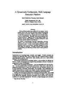
3.1 System architecture The RF network system comprises of both hardware and software components. A typical network configuration is highlighted in figure 1.
415
targets enter the customer's site (within range of the wireless LAN), the end users establish communications session with one-another as providers or consumers of information. An end user is inherently capable of becoming an information provider, consumer, or both.
3.1.2 Application Environment Layer At the highest layer, the AE layer provides the application interface the base station and remote applications end users. The application is inherently distributed between remote (and external) application -users.
......................... i
Base
i.................... Station
1 ~
.... ......... ... .......
'':;,I
A
;
-- - -- - - - -- - .
,
Access Mcdiiim
.............. : .... ..... j
Relay3
;
Units
.........................
j
........................ Network ConEole
~
j
...............................
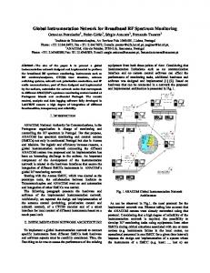
Figure 1: RF System Overview While the architecture contains only three hierarchical layers, it can be directly associated with the OS1 7-layer model. The three-layer architecture (and their association with the OS1 model) is as follows: Applications Environment (AE): includes OS1 Application, Presentation, and Session layer functionality. Communication System User (CSU): includes OS1 Session, Transport and Network layer functionality. Data Communications Network (DCN): includes OS1 Data Link, and Physical layer functionality. Figure 2 illustrates the layered structure used by the architecture and identifies the end users of the application. Layers at the same level have a 'peer-to-peer' relationship. The application environment provides overall control of the application and those services that support it.
3.1.1
Application End-Users
Application end users are the users of the application and the driving force for information interchange. As mobile
a Communication Medium
Figure 2: The System Architecture Layers Processes that are included in the application may or may not be distributed among remote AEs. Those processes that can be executed to completion without the need or support of an external communication system do not require the services of the CSU or DCU layers below them. Instead they rely solely on their parent AE. Because the control center and remote target can be connected directly via an RS232 interface, the radio system must remain transparent to application end-users.
3.1.3 Communications System User Component Distributed application environments, which interact with remote end users, utilize the CSU component. The AE to CSU interface provides the connection point between the application environment and the communications system.
416
IEEE Transaclions on Consumcr Electronics, Vol. 45, No. 3, AUGUST 1999
The CSU component provides the services that are necessary to establish a communications path with one or more remote end-users without the AE being concerned with the characteristics or type of communications medium being used.
and a message trailer. Data characters consist of 8 bit characters (no start and stop bit required) and operate at a standard fixed rate of 9600 bits per second. As we were using Manchester encoding, the radio transceiver operates at twice the bit rate (19.2 K BPS).
3.1.4 Data Communications Network Component
3.2.3 Remote Slave Data Interface
The communication medium that is within the lower layer of the architecture is the DCN. Communication message routing and the communications discipline is the responsibility of this component.
The current application of the radio network is in transportation indushy, mainly for monitoring the food transportation conditions. Most of the loggers monitoring the environmental conditions have a standard RS232 interface, which operates up to 9600 BPS.
3.2 System Interface In this section, we present the system’s interface with the outside world. Mainly, for demonstrating the functionality of this radio network, we have used an RS232 physical interface having enough speed ‘to feed’ the radio transceivers.
3.2.1 Base Station PC serial communications Interface This interface is implemented using the 3-wire RS-232 hardware interface and standard asynchronous communications discipline (one start bit, 8 data bits, and 1 stop bit). The PC to radio module interface, at this stage, operates at 9600 BPS (bits per second). More modern interfaces (like fast RS232, USB, 1394, etc) can be used, involving a minimum amount of changes in the embedded software and in the device drivers used by the controller PC.
This interface includes two RS-232 compatible interfaces. One interface (the primary interface) is implemented using the 3-wire RS-232 hardware interface. The second interface (or secondary interface) is implemented using a standard 5-wire RS-232 interface (i.e. RD, SD, RTS, CTS and GND). Both interfaces adhere to standard asynchronous signal character framing (one start bit, 8 data bits, and 1 stop bit). The interface BPS rate is selectable by the control center PC software by downloading a ‘serial interface rate’ parameter to the remote slave radio module. The radio module will adjust to the specified data rate to operate at 1200,2400,4800, or 9600 BPS. The wide applications range suitable for this radio network makes inevitable a further development for the interfaces provided by the slave devices, such as faster serial ports, USB and IEEE 1394, which today equip most modem electronic equipment.
3.2.2 Radio Communication A single radio frequency channel will provide the wireless communications medium between all radio modules. The radio channel communications discipline is a ‘polled system’ under complete control of the PC network management software. The characteristics of the license exempt medium can vary between countries that this system is used. This is due to governmental restrictions and guidelines for users of the radio spectrum. For the purposes of the initial development, the system was to focus on the following radio frequencies. Europe (excluding UK) 433.92 MHz UHF at 250 microwatts ERP (Effective Radiate Power) USA: 916.5 MHz UHF at 750 microwatts ERF’ UK: 418 MHz UHF at 250 microwatts ERP.
4. System Components 4.1 Hardware components In this section, we present an overall view of the hardware units used in this radio system. The radio system has three main units: base station, relays and slaves. These units are called nodes in the radio network. The main feature of this system is that it supports relays, the routing being completed in a dynamic fashion. The packets into the network are routed using the shortest path into a graph. This is possible thanks to dynamic routing table existing in every packet layout. Each node (both relay and slave) is intelligent, behaving like mini-routers thus the radio system is described as “self-routing”.
4.1.1 Base Station The radio communications discipline is supported by ‘onoff keyed’ modulation utilizing Manchester coding. Radio frames are sent in block synchronous fashion consisting of a message preamble, communications header, body of text,
The base station is the main radio unit in the system, behaving as master in the RF network. It will always initiate a connection with either a slave or a relay device.
~
Uigioi et al.: Transparent, Dynamically Configurable RF Netwotk Suitable for Home Automation Applications
The network topology is a master slave one, to avoid RF collisions that reduce the system bandwidth. Base station functions: Distinguishes between System and Application requestsifunctions. Application requests remain transparent to the radio system. System Management requests can be locally or remotely processed in order to configureimodify systeddevice parameters. All communications consist of framesipackets with headers, body, and trailer, and block/frame check characters to validate integrity of frameipacket. All data fields handled as binary data fields. Error recovery retries remain the responsibility of the system component where the transaction originates (i.e. PC). Standard asynchronous serial port. This unit is connected to the PC running the network management software via an RS-232 cable. Power is supplied via a 9V main adapter.
411
Distinguishes between System and Application requestsifunctions. Application requests remain transparent to the radio system. All communications consist of framesipackets with headers, body, and trailer, and blocWframe check characters to validate integrity of frameipacket. All data fields handled as binary data fields. Error recovery retries remain the responsibility of the system component where the transaction originates. Two asynchronous serial interfaces Slaves have been divided into two categories: class A (Slaves that are a big data consumerisource) and class B (Slaves that have mainly a surveillance function: detect alarm conditions, switch positions, etc). According to the slave class, the control center decides it is worthwhile to optimize the routing path, or it can use the default routing configuration (maximum number of relays).
4.2 Software Components In this section, we describe the software required to manage the radio network, divided in two parts: network management service and network monitor.
4.1.2 Relay Units
4.2.1 Network Manager Service
Up to 15 relays can be installed to form distributed radio network. The relays have two functions: Extend the reach of the network beyond the area directly covered by the base station. Provide multiple network paths to slave units to improve reliability and performance.
This component runs as a background service on a PC or embedded system. It is responsible for all operations on the radio network. Periodically, it broadcasts a query to detect recently arrived slave units. If the slave determines that this site is allowed to access the slave, the slave logs into the network. The Network Manager then schedules this slave for data download or upload.
Power is supplied to relays via main adapters, battery packs or solar panels.
4.1.3 Slave Units These units are mounted on remote targets (intelligent home components, vehicles, etc). In the present application they can be connected to a RS232 port on the remote target. Future implementations will provide more interfaces such as USB, 12C and IEEE 1394. Slave devices can sendreturn tohack to the base station different information such as: the vehicle's engine andor battery status, the home refrigeration unit's status, central hitting settingistatus and many other devices that requires a wireless connection to a central processing unit. The slave units provide two RS232 serial ports for connection to multiple devices. The slave units also have an Alert Signal input, which can be connected to on-off sensors such as door switches, or to alarm signal outputs from homeivehicles equipment. Radio Slave Features:
When there is no scheduled network activity, the Network Manager monitors all slaves and relays for conditions that require action. These could include a signal on the Alert pin, an alarm condition signaled by the target device, or a low battery. The central processing unit, depending on the severity of the condition, can notify the responsible person by fax, email, SMS or normal voice call. The Network Manager operates without any human intervention.
4.2.2 Network Monitor Console This component runs as a normal desktop application on any Windows NT or Windows 95 PC that can access the system (PC or embedded system) running the Network Manager Service. This application provides the user interface to the network system. Through this interface the user can monitor the state of the radio network and the slave units currently present. The user can also see details of slaves that are known to the system, but are not currently present.
IEEE Traiisactions on Consumer Electronics, Vol. 45, No. 3, AUGUST 1999
478
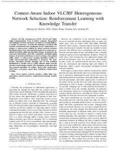
The Network Monitor Console provides facilities to install and configure the system, specify who should be alerted under what conditions and how they should be alerted and obtain reports on the system’s operation. The Windows NT security system is used to allow different degrees of access to different groups of users. For example, some users may only be able to see current status information, while other users can alter the system configuration. A screen shoot presenting the network monitor console is presented in figure 3.
Initialization Phase Normal-operation Phase Termination Phase These operation phases, and their flows, are illustrated in figure 4.
5.1 Radio System Initialization Phase The ‘initialization phase’ is hrther divided into two subphases, they are: Cold start initialization (power up) Warm start initialization (logging-in newly arrived radio slave modules to the site)
5.1.1
Warm Start Initialization
Once a generic module is powered up and assumes its predefined personality, it will remain in the powered-on state indefinitely, with no disruption of power. Warm start initialization is concerned with mobile radio modules that are installed on trucks and trailers and need to notify the base station PC when it arrives to the site. This is accomplished by performing a ‘Logging-in’ of the remote slave to the site and the ‘authentication of the site base station’ to the slave. The base station PC on a periodic basis (every several minutes) initiates the Log-on process.
I Figure 3: Network Monitor Console
5. System Functional Description The base release communication system is directed towards those features and functions that support the: Interrogating for new module arrivals on-site Logging-in of new arrivals Site authentication by remote slave. Transparent application data download from PC to remote target. Transparent application data up-load from remote electronic equipment to PC. Automatic ‘logging-off ‘ of remote slave after leaving site. On-line system configuration and parameter changes
5.1.2
Cold Start Initialization
Cold start initialization begins when power is applied to the radio module. It is intended that at power on, and a short period of time thereafter, the generic radio module will be sensitive to a mode change request. A mode change will allow the generic module to be configured as a radio relay or a remote slave radio module. A generic module cannot be configured as a base station radio device on ‘power-on’. If no change request occurs during the power on delay period, the device will assume its previously configured mode (remote slave or radio relay device). Cold Stan Initialization
In order to maintain a well-structured system was necessary to identify those phases that exist to address the needs of the system and to also support and upgrade the system as required. Three primary phases have been defmed. They include the:
I2L.J Termination
Figure 4:Operations Phases Flow Diagram
~
Lligioi et al.: Transparcnt, Dynamically Configurable KF Nctwork Suitable for Home Automation Applications
5.2 Normal-operation Phase The ‘normal-operation phase’ is entered following a proper logging onto the site. This phase is concerned with: Down-loading application data to the remote target Uploading data from remote target Soliciting remote slave exception and alert conditions. Performing on-line configuration and parameter changes to radio devices. Retrieving radio module status data. The ‘normal-operation phase’ is the normal active state while the radio device is on-site. This phase is entered following ‘log-on’ (warm start initialization) and remains until ‘log-off’ (i.e. for mobile remote slave devices only). All remote slave modules will continually monitor the radio channel. Upon receipt of a valid radio message during the ‘normal-operation phase’, the radio device will ‘retrigger’ an internal logoff timer (discussed below) and check the destination ID or device address of the message received. It the address matches the radio device will process the message further. If no match occurs, the message is ignored and active monitoring begins again.
5.3 Termination Phase The ‘termination phase’ is divided into two sub-phases, they are: Cold termination Warm termination
5.3.1
(device powered off) (device logged-off)
reapplied the radio device enters into the ‘cold start initialization’ phase as discussed in 5.1.2.
6. Conclusions The current radio network implementation is for industrial applications in the transportation industry. It is still expensive for consumer electronics applications. For consumer electronics, the expected market is wide enough to drop the prices down.
The most novel aspect of this system is the use of “selfrouting” capability. Once the relaying problem has been solved, the implementation of the radio network infrastructure was straightforward. Another essential advantage of this system is the fact that the hardware is quite basic, the complexity being switched to the embedded software. This lead to a very low production cost per radio unit. Another important feature of the radio network is that two or more radio networks can work into the same area (radio networks are overlapping). The drawback is that a lower bandwidth results for all the networks that are operating in the same area (radio collisions, etc).
7. References 111 RF Monolithics Inc. “Auulication Notes”: .. hkp://www.rfm.com/corp/apnotes.htm [Z]Blue Tree Systems Ltd. “RadioCom Technical Design Description”: http://www.bluetree.ie
Warm Termination
Warm start termination occurs automatically when the remote radio device determines that is no longer on site (site activity ceases, normal when the mobile target has left the site and is out of radio range). Each slave radio will maintain a ‘log-off timer’. The timer is activated (retriggered) when the radio device receives any valid radio message. This process indicates that the radio device must be in range of the system and hence, ‘on-site’. When the mobile target leaves the site and is out of system radio range, the ‘Log-off timer’ is allowed to expire and a “Warm Termination” occurs. In this state the slave radio remains powered on and continually monitors for new system radioactivity (back on site) where a ‘warm start initialization’ can once again be performed.
5.3.2
479
Cold Termination
Cold termination occurs when the radio device is powered off (i.e. normally by switching off power or by an abnormal loss or interruption of power). When power is
8. Biographies
Engineering at University Collage Galway, Ireland. His research interests include VLSI design, communication network protocols and embedded systems.
480
IEEE Transactions on Consumor Electronics, Vol. 45, No. 3, AUGUST 1999
Alexandru cucos received his B.S. degree in Electronic Engineering from “Transilvania” University Brasov, Romania, in 1997. he is Currently completing his M.S. degree in Electronic Engineering at University Collage Galway, Ireland. His major interests include networking, Internet Technologies, operating systems.
Peter Corcoran received the R A [ (Electronic Engineering) and HA (Maths) dcgrccs from Trinity Collcge Dublin in 1984. He continued his studies at TCD and was awarded a Ph.D. in Electronic Engineering for research work in the of Dielechk field Liquids. In 1986 he was \-. to a appointed