electric field on the internal surface in a Niobium cavity is ... due to the increased transit time factor. ... the transit time factor is a measure of the effective.
Proceedings of 2005 Particle Accelerator Conference, Knoxville, Tennessee
TRAVELING WAVE ACCELERATING STRUCTURE FOR A SUPERCONDUCTING ACCELERATOR P. Avrakhov, PTC of Lebedev Physical Institute, Protvino, Moscow region, 141284, Russia A. Kanareykin, Euclid Techlabs LLC, Solon, OH 44139, USA N.Solyak, FNAL, Batavia, IL
Abstract We present a superconducting traveling wave accelerating structure (STWA) concept, which may prove of crucial importance to the International Linear Collider. Compared to the existing TESLA cavity design, the traveling wave structure can provide ~20-40% higher accelerating gradient for the same aperture and the same peak surface RF magnetic field. The recently achieved SC structure gradient of 35 MV/m can be increased up to ~50 MV/m with the new STWA structure design. The STWA structure is supposed to be installed into the superconducting resonance ring and is fed by one or two couplers (depending on the required input power) with appropriate phase advance to excite a traveling wave inside the structure. We discuss the structure design, optimization of the parameters, tuning requirements and plans for further development.
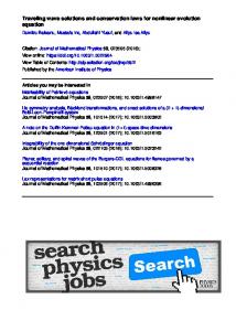
undesirable breakdown of superconductivity. The structure consists of an RF feedback system with a loop waveguide (Fig.1) and can be fed with one or two high power couplers depending on the required rf power level [6,7]. The coupler we propose to use in the STWA cavity design is a standard TTF-III design developed by the TESLA collaboration [1] and recently tested successfully [8]. The input power per coupler needed for the STWA scheme is half of the TESLA standing wave cavity design. The system requires two independent tuners to be able to adjust the cavity and feedback waveguide frequencies and hence to reduce the unwanted backward wave along with overall bandwidth control, Lorentz force and microphonics compensation [1]. Our structure design solution also assumes use of the TESLA piezoelectric tuners. Our proposed scheme would use only previously developed SC accelerator components in addition to the new STWA structure, allowing significant cost reduction and shortening of development time.
INTRODUCTION The principal goal of this paper is to study traveling wave superconducting (SC) accelerator concepts to increase the accelerating gradient of a SC structure and, therefore to reduce the length (and hence the cost) of the accelerator. We bear in mind the recent technological achievements of the TESLA standing wave accelerator design [1,4,8]. We consider here the possibility of developing traveling wave acceleration in a superconducting structure with an accelerating gradient larger by a factor of 1.2-1.4 over the that of the TESLA structure. TeV SC linear collider development requires accelerating gradients of 30 MV/m or higher to be reliably achieved [1,8]. The need for a traveling wave π/2 mode SC accelerating structure arises from the demand for a higher accelerating gradient. The proposed STWA structure will have double the number of cells compared to a TESLA structure and the same aperture of 70 mm. The recently achieved TESLA SC structure gradient of 35 MV/m [8] will be increased in the proposed SC traveling wave cavity by a factor of 1.20-1.40 due to the high transit factor of 0.9. The SC traveling wave π/2 accelerating structure has a nonzero group velocity unlike SC standing wave structures, resulting in a much smaller sensitivity of the accelerating structure to manufacturing and tuning errors [2]. The proposed STWA structure operates at the same surface magnetic and electrical field magnitudes as those on the TESLA cavity surface [1,4,8] to avoid an
c 0-7803-8859-3/05/$20.00 2005 IEEE
BASIC CONCEPTS The accelerating gradient of SC cavities at present is limited by two phenomena, field emission (FE) and thermal breakdown [1]. In principle the gradient is limited by the critical magnetic field for the superconductor (0.20 T for Nb) that implies a maximum possible accelerating gradient of 55 MV/m. In practice the maximum gradient is limited thermal breakdown caused by microscopic defects and field enhancement in the surface of the cavity [1]. A realistic thermal breakdown limit corresponds to an accelerating gradient of roughly 35 MV/m [1,8]. The exact value depends on the detailed structure geometry and on the cavity surface preparation. The maximum electric field on the internal surface in a Niobium cavity is also limited by field emission and multipactoring. There is however no generally accepted limit to the maximum surface electric field, and magnitudes of 100-200 MV/m are widely presented in SC related literature [1,3,4,8]. There are thus two ways to increase the accelerating gradient: maximizing the active acceleration length in a linac and minimizing the electric and magnetic fields at the cavity wall to reduce the possibility of field emission and thermal breakdown [1,3-5,8]. One of the methods for improvement of the accelerating gradient is the use of shortened cells in the accelerating cavity. If an accelerating cavity uses λ/4 rather than λ/2 length cells it results in a considerable gain in the accelerating gradient due to the increased transit time factor. The transit time
4296
Proceedings of 2005 Particle Accelerator Conference, Knoxville, Tennessee factor for single pillbox resonator can be expressed as [1] T=sin(θ/2)/(θ/2)=sin(πDλ)/( πDλ) where θ is the transit angle and D is the resonator length. For D=λ/2, T = 2 π = 0.637 and for D = λ 4 , T = 2 ⋅ 2 π = 0.9 . Since the transit time factor is a measure of the effective accelerating voltage to maximum cell voltage, the accelerating rate of a λ/4 pillbox is 2 = 1.41 times higher than in a λ/2 length pillbox. The λ/4 length accelerating cells have an additional advantage when used in a traveling wave structure operating in the π/2 mode .
STWA Structure Design. The group velocity (along with the quality factor) of a linear accelerator section defines the filling time of the structure and usually does not exceed few percent of the speed of light. During the filling time part of the power is dissipated in the absorption load at the RF structure output. After the structure is filled all the power is transferred to the beam. In the case of non-ideal loading a reflected wave propagates backward and by interference with the forward accelerating electric field results in an undesirable RF field enhancement at the structure walls. (The reflected wave does not, however, interact with the electron beam) [1-3].
Figure 1. The resonant loop of the superconducting traveling wave accelerating structure powered with two TESLA TTF-III 250 kW couplers spaced at (n+1/4)⋅λwg .
Double-Coupler Power Feed These two factors encouraged us to consider a simpler scheme [3,5,6] requiring less development time with the same feedback loop and one or two (at high power level) previously developed TTF-III couplers used now for feeding the SC traveling wave structure, Fig.1. It should be noted that in the STWA structure scheme the power passing through each coupler is less than half that of the coupler in the TESLA design [6]. It is critical in our case to prevent backward wave generation in the STWA. A traveling wave resonator with a feedback loop has two orthogonal standing waves resulting in a traveling wave only if the standing waves have equal magnitudes and their phase shift is of π/2 [6] The mode frequencies must be degenerate in order to have equal forward and backwards amplitudes. This means that we have to tune the mode frequencies independently to obtain a) equality of both mode frequencies within a bandwidth of few x100 Hz, and b) Lorentz force compensation and microphonics reduction [1]. The same principal frequency shift compensation system has been applied previously in the development of the Gyrocon and Magnicon high power sources [6]. It should be mentioned here that this problem can be rephrased as that of maintaining the resonant frequency of the standing wave cavity within the defined frequency bandwidth [6]. The TESLA superconducting cavity frequency is fixed with specially designed piezoelectric tuners [1] that adjust the frequency defining geometry of the cavity while the energy is being stored in the structure. We found that a double-piezoelectric tuner system is needed for STWA structure frequency control. The RF power of the STWA structure will be provided by two TESLA TTF-III couplers [1] spaced at a distance corresponding to (n+1/4)⋅λwg where λwg is the wavelength of the STWA structure. Single-Coupler Power Feed
We propose to utilize the accelerating wave passing through the linear accelerating section by redirecting it back to the input of the accelerating structure. The proposed scheme of the rf wave circulation in the rf structure is the well-known traveling wave resonator solution [2]. The energy out of the generator goes into the ring resonator (or feedback loop) through the directional coupler to define by the phase relations the correct direction of the rf propagation in the acceleration section. One can consider the SC feedback loop system with the directional coupler design that was presented and discussed in detail in [3,5]. This concept can be applied to TESLA-like machines [1,4] but a π/2 TW structure requires a special SC directional coupler design. The development of this coupler is a challenging task. The helium vessel and cryostat designs for the directional coupler scheme may require some changes as well [1].
The STWA can be powered by a single coupler as a conventional TESLA cavity. This is possible when the frequencies of two space-harmonics (or polarizations) are detuned by ±f0/(2Q) from the working frequency f0, where Q is the loaded quality factor. The position of coupler should be chosen such a way to excite both polarizations with the same amplitude. Due to frequency detuning the phases of two polarizations are shifted by ±45 degrees according the coupler phase. So, a single coupler will excite two standing waves with the equal amplitudes but with 90 degrees phase difference. The resulting wave will be traveling wave. This idea was already demonstrated in the high power C-band gyrocon, where a circular polarized TM011 mode in the input cavity was excited by one coupler [7]. The frequency of the cavity and mode were tuned separately. More detailed simulations of this
4297
c 0-7803-8859-3/05/$20.00 2005 IEEE
Proceedings of 2005 Particle Accelerator Conference, Knoxville, Tennessee scheme for the STWA are needed to define parameters and tolerances.
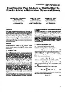
STWA Structure Parameters In this section we present the optimal geometry simulations for the STWA cavity. The shape of the STWA cell has been chosen to be close to the TESLA design [1,3,5], (Fig. 2). Even our preliminary calculations show the accelerating gradient increasing significantly.
gradient for the increased peak surface electric field ratio of 2.19 [1,8] gives an accelerating gradient of 48.4 MV/m. The optimistic gradients for the peak surface magnetic field of 200 mT (limit field) [1] are given in the last row of Table 1. Parameter
TESLA-500 9-cell cavity
STWA, low Epeak
STWA, high Epeak
Active length Number of cells Aperture diameter Coupling cell to cell R/Q per cavity (Ω) Epeak/Eaccel Bpeak/Eaccel (mT/Mv/m) Eaccel (mT/Mv/m) at Bpeak ~ 150 mT Bpeak ~ 200 mT
1.038 m 9 70 mm 1.87% 1036 2.0 4.26 35.2 46.9
1.038 m 18 70 mm 5.20% 1550 1.702 3.58 41.9 55.8
1.038 m 18 70 mm 6.84% 1750 2.19 3.1 48.4 65.5
Table 1: Comparison between TESLA 9-cell cavity and two STWA structure configurations.
SUMMARY Figure 2. Superconducting traveling wave accelerating (STWA) structure cavity shape. For the maximum electric and magnetic fields at the STWA structure surface equivalent to the TESLA niobium cavity the accelerating gradient gain will be about a factor of 1.2. At the same time there has been tremendous progress recently in increasing the critical electric surface field for niobium SC cavities of different geometries and material treatments [1,8]. A surface field of 100 MV/m has been achieved along with the accelerating gradient of 44-45 MV/m [8]. Fields up to 220 MV/m have been imposed on a superconducting niobium surface without any catastrophic effects [8]. The length of the STWA cell is equal to 1/4 of the free space wavelength, the sidewall is rounded off the same way as the omega-shaped TESLA cavity, and the aperture is ellipsoidal, (Fig. 2) [5]. The maximum electric field for this configuration occurs close to the aperture edge, and the maximum magnetic field will be reached at the sidewall of the cavity. Thus, there is a possibility to optimize the cell geometry of the cavity that has a minimum surface magnetic field to accelerating gradient ratio, the tradeoff being an increase of the surface electric field by the same ratio. Table 1 presents a comparison of the TESLA-like standing wave accelerating structure with two optimized cases for the STWA, one with the lower surface electric field of 70 MV/m and a higher of 100 MV/m. One can see that the accelerating gradient in the low field case is 41.9 MV/m, 19% high than in the TESLA structure. The accelerating gradient demonstrated recently was 35 MV/m [8]. It should be noted that the accelerating
c 0-7803-8859-3/05/$20.00 2005 IEEE
A Superconducting Traveling Wave Accelerating (STWA) structure has been proposed. The STWA structure has an important advantage in comparison with the recently developed 9-cell TESLA cavity: increased accelerating gradient by up to 20% (42 MV/m) while maintaining the same TESLA magnetic and electrical surface field ratios Epeac/Eacc and Bpeak/Eacc. and allowing the higher acceleration gradients that are a goal of the superconducting accelerating community. The feedback loop design along with the one- and two- TESLA TFT-III couplers feed systems have been studied. The proposed STWA cavity geometry has been optimized to achieve the maximum available accelerating gradient for specified cavity surface fields.
REFERENCES [1] H.Padamsee, J.Knobloch, T.Hays. RF Superconductivity for Accelerators. A WileyInterscience Publishing, 1998. [2] G.A. Loew, R.B.Neal, in book: Linear Accelerators. Ed. P.Lapostole, E.Septier. North Holland Pub. Comp., pp.77-87, 1970. [3] Balakin V.E., Solyak N.A. Branch of INP 98-01, pp.144, 1998 [4] http://tesla.desy.de/new_pages/TDR_CD/start.html [5] Avrakhov P. TESLA report meeting, Orsay, 1997. [6] V.Yakovlev. Private communication. [7] Balakin V, Solyak N et.al, Proc. of IV Conference on High Peak Current Beam Electronics, Tomsk,1982. [8] ILC 1st Workshop in KEK, November 2004, KEK, Japan
4298