Trigger implementation in the KLOE experiment. V. Bocci. 2,(*). , P. Branchini. 4. , F. Bossi. 5 .... a series of monitor registers to control dead time, arrival timing of ...
Trigger implementation in the KLOE experiment 2,(*)
4
5
5
2
V. Bocci , P. Branchini , F. Bossi , G. Felici ,M. Gatta , 2 3 2 1,5 1,5 R. Messi , G. De Robertis ,M. Palutan ,V. Patera , A. Sciubba 1 2
Dipartimento di Energetica dell’Universita, Roma I
Dipartimento di Fisica dell’Universita‘ e Sezione INFN, Roma II (*) now INFN sezione di Roma, Italy 3
INFN Sezione di Bari, Italy
4
INFN Sezione di Roma3, Italy
5
Laboratori Nazionali di Frascati dell’INFN, Frascati
Abstract. The KLOE detector at present under operation at the Frascati phi-factory DAΦΝΕ is a general-purpose detector for the study of CP violation in the neutral kaon system. The KLOE trigger uses signals from both the electromagnetic calorimeter and the central drift chamber. Within 150 ns after an interaction the calorimeter and the drift chamber provide a set of signals which form the basis of the trigger decision. The design of the modules providing the trigger decision for each sub-detector, the final trigger decision together with the modules for distribution and synchronization in the experiment is presented. Particular emphasis will be given to the presentation of the use of modern design methodologies that could be also implemented for the realization of electronics for LHC experiments.
Outlook The KLOE trigger uses signals from both the electromagnetic calorimeter and the central drift chamber. The final trigger decision and the its distribution are performed by VME modules with two data acquisition interfaces: The VME one and a custom designed KLOE AUXbus backplane. VME is used for setting and calibration purposes, while the AUX-bus provides the interface the data acquisition system. Monitoring of the data at each stage of triggering process is necessary for data consistency checks and to keep the entire system under control . Actually this data allow the determination of all trigger efficiencies with the required precision togeteher with a detailed investigation of possible systematic effects due trigger system.
The modules of wich perform the trigger decisions for each subdetector contain counters, shift registers, status registers, and a fast data acquisition interface. The trigger distribution system contains the logic for trigger handling and the logic for broadcasting the synchronization cycle, needed to check the properdistribution of the exact trigger number to all the front-end boards of KLOE. All control and acquisition logic is implemented in FPGAs. In the design of the trigger modules HDL (Hardware Description Language) code for simulation was used, together with synthesis tools to target the function in FPGA devices. ECLinps logic and analog sum are used for fast part. The use of HDL permits the reuse of code for new design in different targets and an easy way to upgrade existing boards with new function, without PCB redesign.
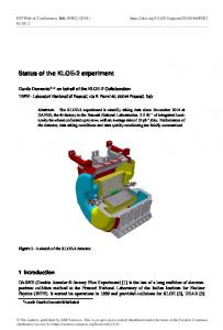
The DAΦNE Φ Factory and the KLOE detector. DAΦNE is high luminosity e+e-collider, built in Frascati, Italy. Its CM energy is set at the Φ meson resonance, 1020 MeV. About 35% of the Φ decays in KLKS (KL- in πππ and KS in ππ) while only a small fraction (about 0,3 %) are CP violating events (with KL decaying in ππ).
Fig 1. The KLOE detector inside DAΦNE.
32
-2
-1
The designed peak luminosity is 5 x 10 cm s wich corresponds of Φ rate of about 2.5 kHz. The Kloe experiment [1], currently on run at DAΦNE, has been optimized for the measurement of the CP violation -4 parameter Re(ε’/ε) to a precision of 10 . It consist of large helium tracking chamber for momentum measurement and a lead scintillating fiber elettromagnetic calorimeter with excellent timing performances. The entire detector operates inside 6 kGauss solenoidal field provided by superconducting magnet.
The KLOE Trigger. The KLOE trigger [2],[3] strategy is based on local energy deposits in calorimeter sectors and multiplicity information from the drift chamber. A two level scheme has been adopted in order to both produce an early trigger with good timing information to start the FEE operation and to exploid as much information as possible from the drift chamber, whose typical response time are in the microseconds scale. Therefore after the arrival of a first level trigger, additional information is collected from the drift chamber, which is used, together with the calorimetric information, to start the DAQ system. The trigger decsion can be vetoed at the first level in the case the event is identified as Bhabha scattering or at the second level in case of cosmic ray events.
• T1sync is the T1 synchronized with the accelerator RF , and distributed by the Trigger Distributor board (TD) with a jitter less than 50 ps . • T2Y is a signal, generated by the TORTA as a second level trigger, which takes into account the full information from the Drift Chamber and supplementary EMC information. It is ready and sent to the Trigger Supervisor (TS) in a range between 200-1500 ns after T1 (depending on wich subdetector is providing the validation). • T2 is generated by the TS with a constant delay of about 1.8 – 2 µs after T1 and distributed to the FEE if a T2Y from the TORTA was received. Its jitter needs to be less than 1ns. • T1ACK is an acknowledge level which is asserted by the TS upon the receipt of a T1 signal from the TORTA. It is deasserted at the end of a fixed time delay, independently on an eventual T2 generation, and if no BUSY condition is detected by the TS. T1ACK acts as a DISABLE signal to the TORTA. In case of a Golden Number Trigger, T1ACK remains asserted during the synchronization cycle. The Trigger distributor. Due to the very stringent timing requirements one of the most critical signals is T1sync, which is distributed to the ADCs and TDCs via the AUXbus backplane by using two differential lines [4]. Actually if a precision of 1ns is already an issue, 50 ps require a more sophisticated and cautious design of the line. The Trigger Distributor (TD) distributes to the FEE the T1, directly received from the TORTA, after having synchronize it at 92,06 MHz, i.e 1/4 of the DAΦNE machine clock (368,25 MHz). The synchronized T1 is then fan-out, via a dedicated coaxial cable. Laboratory mesasuraments give for tese module the following performances: o
Max Temperature jitter