standards: FOUNDATION Fieldbus; WorldFIP; and the. CAN bus, each of which have great advantages over traditional instrumentation networking technology.
Truly Distributed Control Systems using Fieldbus Technology AV Scott and WJ Buchanan Napier University, Edinburgh, UK { a.scott | w.buchanan } @napier.ac.uk
Abstract This paper outlines the three main field bus type standards: FOUNDATION Fieldbus; WorldFIP; and the CAN bus, each of which have great advantages over traditional instrumentation networking technology. The paper shows, using their specification, how they improve traditional control and data acquisition methods. By analysing the main fieldbus types the paper shows how the are more robust, how the can be used to distribute data around the control system (rather than centralise it in traditional systems), provided increased diagnostic information, are easy to implement, fault confinement, and move simple control operations from the main controller to the local environment. This will help to segment industrial plants into zones which can control themselves. The main control will then be responsibility high-level control, and interzone communications. The paper concludes by discussing how fieldbusses will answer many of the problems of previous control and data acquisition systems.
1. Introduction Field buses are special local area networks that are dedicated to data acquisition and the control of sensors and actuators. They typically run over low-cost twisted pair cable. They differ from many traditional LANs (such as Ethernet) in that they are optimised for the exchange of short point-to-point status and command messages. Many Fieldbus standards that exist each developed for a specific purpose. Sales
4-20mA analogue
Serial links
Fieldbus 3-15 PSI
Time 1930
1960
1990
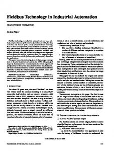
Figure 1 Market for instrumentation parameter transmissions
The potential market for Fieldbus equipment is enormous. The expected market by 2003 is likely to be
over 50%. Instrumentation interfaces have evolved from 3-15psi transmitters, to 4-20mA analogue interfaces, now to serial interfaces (typically either RS-232 or RS-485) and now to Fieldbus interfaces. This evolution over time is illustrated in Figure 1.
2. Fieldbus types The main field bus types are outlined in this section: FOUNDATION Fieldbus (which is a truly open standard); WorldFIP (which are supported by many major vendors); and CAN bus (which is used in the automobile industry). There are three main categories for Fieldbus installations, these are: Fieldbus standard; other domain standards and Non-Fieldbus. The main Fieldbus standard are WorldFIP (standard in France), Profibus (standard in Germany) and P-Net (standard in Denmark), and are all part of the CENELEC European standard EN 50170. WorldFIP has the advantage over the others in that it uses the IEC physical layer (the IEC 1158-2). The Fieldbus Foundation is an initiative of mainly USA-based vendors. Its main aim is to standardize Fieldbus for the petrochemical/chemical industries. One of its aims is not to replace traditional DCS’s (Distributed Control Systems), but to integrate with them. The main standards for Fieldbus products are: x Fieldbus Foundation. This was formed 1994 have defined low speed 31.25kbps transmission (H1). The H2 standard (which is equivalent to WorldFIP) will operate at 1Mbps. x WorldFIP (or WorldFIP Europe). This standard has been incorporated into many products and supports a 1Mbps-transmission rate. WorldFIP contributes to the Fieldbus Foundation, in their standardisation process. x Profibus. This has three main types: FMS (Flexible Manufacturing Systems), DP (Distributed peripherals) and PA (Process Automation). FMS and DP use RS-485 signalling, whereas PA uses the IEC physical layer at low speeds. FMS and DP are part of EN50170. Other busses, such as the CAN bus, use only the lower layers of functionality, especially for remote I/O. The CAN bus is a truly distributed control system as it does
not need a controller to control the flow of data between nodes. The CAN protocol is an ISO defined standard (ISO 11898) for serial data communication at bit rates up to 1Mbps. It was initially developed for the automotive industry, and has the great advantage that it uses a common bus which reduces the need for wiring harnesses. It has since outgrown this application. The standard includes a physical layer and a data-link layer, which defines different message types, arbitration rules for bus access and methods for fault detection and fault confinement. The CAN bus uses Non-Return To Zero (NRZ) with bit-stuffing for the physical layer. A bit can either be dominant (a logical 0) or recessive (logical 1), which corresponds to certain electrical levels which depend on the physical layer used. Modules are connected to the bus in a wired-AND, thus if one node puts the line to a dominant level, then the whole line goes to this state, regardless of the other levels on the line.
3. FOUNDATION Fieldbus FOUNDATION Fieldbus, is an open specification for sensors, actuators, analysers, and so on. It allows: x The control functionality to actually reside in field devices. x The support of other diagnostic, process operation and maintenance functions within field devices. In the past, 4-20mA standards have been used to transmit plant information to controllers. This has in some places, been replaced by transmitter vendors providing their own digital protocol to allow bi-directional communication between the control system and smart transmitters. Fieldbus has finally allowed a standardized method for process control to move from being centralized to become distributed, and the control to actual reside in field devices, such as transmitters, values and analysers. It provides a digital communications channel and a user layer to provide intercommunications. Its benefits are: x Interoperability. This allows different suppliers to be used for devices. x Wiring cost savings. One communication channel can transmit many digital signals. x Flexible control implementations. x Increased field information. This includes processed data, averages, minimas, maxima, diagnostic information and operational information.
interconnection of sensors, actuators, instruments and control systems. The Fieldbus Foundation has since set out to commercialise it as the FOUNDATION Fieldbus.
3.1 Fieldbus topology Most analogue transmission methods, and many digital field communications methods, require a single twisted-pair wire for the transmission of a single process variable. Fieldbus differs from this in that it can connect buses point-to-point, with spurs, as a daisy chain, as a tree, or as a combination of any of these. The methods are: x Bus with spurs. All the devices connect to a common bus and they connect through junction boxes, as illustrated in Figure 2. x Daisy-chained. All the devices are chained to each other, one-by-one. It is similar to the bus with spurs, but does not use junction boxes. It is a useful method of connecting devices as new devices can be added by simply daisy-chaining from a close device. The disadvantage is devices must be disconnected in order to connect a nearby device, unless a special connector can be used that allows a connected device to be connected. x Tree. This type of topology uses a single junction box, with the devices connecting directly to the junction box. Typically, it is used when devices are added and deleted from the network on a regular basis.
Daisy chain
PLC
Sensor/ Actuator
Sensor/ Actuator
Sensor/ Actuator
Sensor/ Actuator
Junction boxes
Bus, with spurs
PLC
Sensor/ Actuator
Sensor/ Actuator
Sensor/ Actuator
Sensor/ Actuator
Junction boxes
Tree
PLC
Sensor/ Actuator
Sensor/ Actuator
Sensor/ Actuator
Sensor/ Actuator
Figure 2 Fieldbus connection topologies
Fieldbus was initially defined by the ISA’s SP50 fieldbus standards committee, which outlined a two-way, multidrop, digital communications standard for the
3.2 FOUNDATION Fieldbus layers
blocks, vendor-enhanced function blocks and vendorcustom function blocks. Two of the blocks are:
Process control communications can be group into three different levels:
•
x Hardware-address buses. This type of bus uses hardware addresses and registers to store values. Examples are I/O buses, PLCs, SCADA protocols with RTUs (remote termination units). x Symbolic addressed buses. This type of bus uses addresses that actually have a symbolic name. This works at a high-level than the hardware-address bus. x Comprehensive user-layer functionality buses. This type of bus operates at a higher level than hardware and symbolic addressing. It is used in the FOUNDATION Fieldbus and supports function blocks, standardized parameters, operational modes, cascade initialisation sequences, anti-windup mechanisms, quality-of-data propagation and response, fail-state initiation, alarm reporting and control mechanisms, process control data structures, and so on. The FOUNDATION Fieldbus consists of two main layers: the Communications Layer and the User Layer. The components in these layers are illustrated in Figure 3. The User Layer operates above the communications layer and includes Function Blocks, Resource Blocks, Transducer Blocks and Alarm Notifications.
•
Resource blocks (RB). Each device also has an RB, which contain parameters relating to the physical device, such as manufacturer ID, device type of device, revision, memory usage and free space, computational time and device state (On-line/offline/standby/fault condition/etc). Transducer block (TB). Each device has a TB, which the named entity that stores the parameters associated with the sensor or actuator.
3.4 Alarm notifications Each block (functional, resource or transducer) can produce an alarm notification which is associated with that particular block, such as process problems with function blocks, sensor/actuator problems with transducer blocks and overall device problems with resource blocks. The devices each have parameters, which are structured using an object dictionary, in a standardized method of interrogating and referencing parameters over the communications link. In FOUNDATION Fieldbus there are 16 priority levels divided into four classifications: Priority (0) disables alarms including the setting of the alarm condition status flag; Priority (1) disables report, but causes the status flag to be set; Priority (2-7) sets advisory alarms and Priority (8-15) sets critical alarms.
Resource Block
Fieldbus network
3.5 Device description language (DDL)
Communication Protocol (Data Link) Communication Interface (Physical)
Function Block Object Dictionary
Transducer Block Input/ output signals
Function Block Shell Function Block
Transducer Block
Figure 3 FOUNDATION Fieldbus architecture
3.3 Function blocks (FB) The User Layer supports device configuration, and uses function blocks. A device can have any number of function blocks [1–4]. These are used for control, diagnostic, safety and production accounting purposes, and define such things as standardized parameter names, data types, a cascade initialisation mechanism, status propagation, trend collection mechanism, an execution scheduling mechanism, block modes and behaviours in response to mode changes, status of process variables, rules for propagation of status and behaviours in response to status changes. They include standardized function
The FBs, TBs and RBs are not just limited to a standardized set of parameters, a new DDL allows manufactures to specific additional parameters in a standardized manner. This includes names, data types, enumerations, units, valid ranges, user entry limits, entry conditions (such as out-of service or manual mode), connection properties, presentation information and help text. Updates can be easily installed with DDs (Device Description), which is a compiled form of DDL. This allows easy updates and bug fixes on equipment, as updates can be downloaded onto the equipment.
3.6 Control The two main control advantages of the Fieldbus are that it truly distributes control and that control processing can be done concurrently (rather than being centralized in a controller). The devices can implement many of the control functions that a traditional DCS would do. Most of the control functions are implemented by: x Two input blocks (analogue and digital).
x Two output blocks (analogue and digital). x Six control blocks, such as PID (proportionalintegral-derivative). Other, less well used, control functions include pulse input, arithmetic, dead time, splitter and signal characterization. Most current control systems use a DCS (Distributed Control System) to control and the transmitter simply determines the process variable. Smart transmitters will change this as basic regulatory control can be moved to the transmitter. This reduces the loading on the controller, and as the functions become more complex may eliminate the controller all together. Control with Fieldbus is relatively easy if the devices are located on the same bus, and are located in near proximity, and if the elements of control are located relatively close to each other. This allows function blocks to be linked without having to span different bus segments, and thus reduces delays. Messages on the bus are divided into two classes: x Cyclic. These messages involve process data which is transferred between linked function blocks and can be made part of a network. x Acyclic. These are single transfers of data. The scheduling of these is determined by the control equipment and is flexible in its approach, thus allowing the bandwidth to be used effectively.
3.7 Diagnostic information Maintenance methods differ from plant to plant. These are: x Preventative maintenance (PM). This is where plant is inspected and, if necessary, replaced, before faults occur. In some cases, PM can cause more problems than it is worth, because when a piece of plant is disturbed it can often lead to faults that would not have happened. Unfortunately, to operate PM properly, it requires a great deal of information about the operation of the plant for its previous history. x Deferred maintenance (DM). This is where maintenance is deferred to save costs. Unfortunately, deferred maintenance can often lead to long-term costs, typically causing plant shutdowns, complete rebuilds for expensive equipment or leading to an unsafe plant. In the past manufacturers have built in diagnostic information to micro-processor-based devices. Unfortunately, the method of implementation has been non-standard. Typically, each diagnostic signal required an additional 4-20mA signal to be sent to a host or DCS. In some cases, a proprietary digital protocol allowed the
transmission of multiple diagnostic signals over the same pair of wires. This all required extra control system programming and alarm handling. The Fieldbus overcomes this with a standardized comprehensive alarm reporting mechanism and the DDL. A host or DCS supporting Fieldbus does not require any special configuration or programming to accept the manufacturer-specific predictive diagnostic information. The diagnostic information can be used to determine when a device needs to be maintained or replaced. For example, an instrument may have a battery backup. The microprocessor can then monitor the voltage level of the battery. If it falls to a given value, the microprocessor can report an alarm that the battery requires maintenance. The intelligent plant that warns its operators when it is about to fail is one step closer. The Fieldbus allows for peer-to-peer communications. Thus, intelligent sensors can talk to each other, and allow the interaction of devices, typically to make calculations from process measurements, that allow instruments to determine if a fault is localized or due to a process upset.
3.8 Operational Information In the transmission of 4-20mA, analogue signals reduces the resolution of any measured value. As the Fieldbus uses digital technology, the resolution of the measured signals does not depend on the transmission channel, and only on the sensor and its associated analogue-to-digital conversion. The TB passes transducer passes the measured signal, which has been compensated for operating conditions, to the FB which converts the value into the required units. The Fieldbus allows for 6.5 decimal places of precision with the desired engineering units. Typical operation information includes: x Range values, engineering units, secondary variables, serial number or tag name, calibration information, calibration date, materials of construction, and time stamping. x Trending/calculations. From these measurements, statistics such as minimum, maximum, rms and average values can be logged and trended, over any time interval. The operation can be controlled by certain events, such as process start-up, process changes, time events, and so on. System time is automatically synchronized between devices. These values can be stored and automatically reset without the host or DCS having to control the operation. In custody transactions, such as gas/oil flow rates, values can be automatically stored and not tampered with by external parties. The calculation of trend releases the processing of a centralized system and also reduces network traffic, as the host or DCS only has to communicate with the Fieldbus device when it requires information.
x Device-related statistics. These include device identification (such as ID, model number, and so) and operation parameters, such as operational time, number of alarm conditions, number of power-ups, and so on, and are typically used in maintenance records.
Function moved to the field: • Low-level control. • Parameter calculation. • Alarm handling. • Local area control.
Centralized host/ DCS
3.9 New installations and upgrades Fieldbus has the greater advantage in new installations in that it can significantly reduce the amount of cabling on the plant, and provide an increased amount of information than many other digital protocols. It also allows different venders equipment to be used (as long as they abide with a Fieldbus standard). On an existing site it is often difficult to justify the complete upgrade of a plant, as plant upsets can lead to financial losses. Thus, many vendors allow existing equipment to be upgraded. This normally requires a change of hardware, but is difficult in hazardous environments. A more typical situation is to replace failed devices with new smart transmitters, but this obviously requires a change of host software to be able to communicate with the device. There has been considerable investment in DCSs. For Fieldbus to be a success it will have to be integrated with existing DCSs. The DCS will then change its functionality from low-level/high-level control to implementing high-level control, leaving the low-level control to the Fieldbus devices, as illustrated in Figure 4. Functions which will move from the DCS to the Fieldbus: x x x x x x
Low-level Control. Process Parameters. Alarm Generation. Calibration information. Device Status. Area Control.
The DCS will still be responsible for the high-level control functionality and the interoperatiablily between areas [4,5]. Thus, the functions that will stay on the DCS are: x Advanced Control. x Interarea Control (bring together the control of areas). x Production Co-ordination. x Centralized Configuration. x Alarm filtering. x Network Administration. x Communicate with devices and service their requirements. x Maintain an overall database.
DCS responsible for: • Advanced Control. • Interarea Control. • Production Co-ordination. • Centralized Configuration. • Alarm filtering. • Network Administration. • Maintaining a Global Database.
Area
Smart transmitters responsible for: • Low-level control. • Process Parameters. • Alarm Generation. • Calibration information. • Device Status.
Smart transmitter
Area
Smart transmitter
Figure 4 Functionality of a DCS/Fieldbus system
4. WorldFIP WorldFIP [7] operates at 1Mbps over twisted-pair cables, and is a reliable method of transmitting variables (from sensors and to actuators) and messages (such as events, configuration commands). It uses a bus arbitrator that broadcasts variable identifiers to all the nodes on the network. This triggers the required node which produces the node to respond with the required value. All modules that need this value must then read it. Its main characteristics are: x It supports a distributed, decentralised database of variables. x It does not require node addresses as messages are broadcasted by a bus arbitrator, and then the response is from the node which contains the processor parameter. The WorldFIP protocol is an open system, international fieldbus standard (EN50170) and is used to interface to Level Zero (sensors and actuators) and Level One (PLCs, controllers, and so on) devices. It can be used in many different architectures, such as centralized, decentralized and master-slave. The control algorithm can be located within a single processor or can be distributed. Figure 5 shows the layers of the WorldFIP standard [8,9].
x Frame End Delimiter (FED). A predefined pattern of 1V+V–V+V–101, which defines the end of the CAD field.
subMMS (Subset of Messaging Services)
MPS (Manufacturing Periodical/ APeriodical Services)
Network Management
MCS (Message Control Services)
Data Link Layer
V+ 0
CAD
V− 1 0 1 0 1 0 1 0 1 V+ V− 1 0 V − V+0 PREAMBLE
FSD
1 V+ V− V+ V− 1 0 1 FED
Figure 7 WorldFIP frame Physical Layer
4.2 Data link layer Figure 5 WorldFIP layers
The data link layer supports two types of service:
4.1 Physical layer The physical layer ensures the transfer of bits from one device to another. In the main specification the transmission rate is 1Mbps over shielded twisted-pair (STP) or optical fibre cable. The three defined rates are S1 (31.2 kbps), S2 (1 Mbps) and S3 (2.5 Mbps) and an additional speed of 5 Mbps (fibre optic). As Ethernet, WorldFIP uses Manchester coding. This codes a ‘1’ as a high to a low transition, and a ‘0’ as a low to a high transition, as illustrated in Figure 7. A constant high or a constant low level is a violation to the coding. A high level is a V+ volition and a low level is a V– violation. Manchester coding has the advantage of embedding the clock within the transmitted signal. ‘1’
‘0’
T
T
Figure 6 WorldFIP bit coding
x Exchanges of variables. x Message transfers. which can either be cyclic or an explicit user request. A cyclic message is when the system configures object names. These exchanges are automatically sent without the user requesting them. An explicit user request involves requesting variables and the related response.
4.3 Addressing WorldFIP has two addressing modes, these are: x Variable addressing. This is a global addressing scheme, where each variable in the distributed system has an associated identifier, which uniquely identifies the variable. Each identifier is a 16-bit integer value. A device requesting the variable does not need to know the location of the variable, and uses broadcasting to all connected devices. x Message addressing. This is an addressing scheme which uses a 24-bit address for each device on the segment. Each address identifies the network segment and the node address on that segment.
The frame start sequence (FSS) is illustrated in Figure 8, and contains the following fields:
4.4 Application layer-Physical layer interfaces
x Preamble (PRE). A predefined pattern of 10101010. This is used to synchronize the receiving clocks. x Frame Start Delimiter (FSD). A predefined pattern of 1V+V–10V–V+0, which defines the start of the CAD field. Note that violations (V+ and V–) cannot occur within this field. x Control and Data (CAD). Contains information on the data link layer.
The data link layer provides an interface between the application layer and the physical layer. It consists of a number of produced and consumed buffers, which contain the latest values updated by the user or by the network. These buffers are overwritten when the value is updated, and are automatically created on the initial configuration of a station. Transactions involve passing an ID_DAT frame, which is followed by an RP_DAT frame. The format of these is illustrated in Figure 8. Frames begin with a control byte which allows network devices to determine
the frame type. It is used to identify variable transfer requests, acknowledgement frames, and so on. Frames end with a Frame Check Sequence (FCS) which is used to provide error detection. FTR 2 bytes FTR 2 bytes
Control
Identifier
FCS
DTR
1 byte
2 bytes
2 bytes
1 byte
Control 1 byte
INDEN
Control
DATA
FCS
DTR
n bytes (< 128B)
2 bytes
1 byte
ID-DAT
RP-DAT
Application layer
USER DATA
Data link layer
FCS
FTR FSD
bus, a dominant level is represented by a logical zero and the recessive level by a logical one. x Recessive level. A recessive level on the bus is always overruled by a dominant level. If all levels are at a recessive level, the resulting level will also be recessive. In a wired-OR connection, a recessive level will be a logical zero (as a single logical one level will make the output also a logical one).
DTR
Physical layer
Figure 8 WorldFIP frames
5. CAN Controller Area Network (CAN) [10] was developed mainly for the automobile industry, and is now popular in factory automation. It transmits at 1 Mbps and uses twisted-pair cable, for, up to, 40 devices. Its main features are: x Nodes can communicate when there are no nodes communicating on the bus. x It uses a non-destructive bit-wise arbitration which allows fast detection of multiple accesses. This allows full use of the bandwidth. This differs from bus-topology LAN technologies, such as Ethernet, which detects collisions over long distances, and suffers from propagation delays, and nodes may transmit many bits before they can determine if two or more nodes are communicating at a time. In Ethernet, nodes back off from the network when a collision occurs. x Message priority system, which is based on an 11-bit packet identifier. x Architecture can be many masters, and involves peerto-peer communications or multicast transmissions. x Automatic error detection, signalling and retries. x Short data packets of eight bytes.
5.1 Bus values The CAN bus defines two levels for bits on the bus [11], these are: x Dominant level. All nodes on the bus connect to the common bus. A dominant bit will always overrule a recessive bit. In a wired-AND implementation of the
Message bit streams uses a Non-Return-to Zero (NRZ) technique. The frame segments START OF FRAME, ARBITRATION FIELD, CONTROL FIELD, DATA FIELD and CRC SEQUENCE are coded using bit stuffing. When the transmitter detects five consecutive bits of identical values in the bit stream, it automatically adds an extra complementary bit in the actually transmitted bit stream. When the receiver detects this is automatically deletes the inserted bit. In DATA FRAMEs and REMOTE FRAMEs, the CRC DELIMITER, ACK FIELD and END OF FRAME are not stuffed. ERROR FRAMEs and OVERLOAD FRAMEs are not bit stuffed.
5.2 Error detection A key component in creating a reliable bus is to provide strong error detection. The main method that the CAN bus uses to detection errors is by monitoring bit levels. For this transmitters check the transmitted level with the level on the bus, and can quickly detect collisions on the bus. At a higher level, cyclic redundancy check, bit stuffing and message frame check are used. The error detection scheme detects: all global errors, all local errors at transmitters, up to five randomly distributed errors in a message and burst errors of length less that 15 in a message. The resultant probability of undeleted errors is less than 4.7×10⁻¹¹.
5.3 Message transfer Message transfer [12] involves four different frame types: x DATA FRAME. Contains data from a transmitter to a number of receivers. x REMOTE FRAME. Transmitted by a unit to request the transmission of the DATA FRAME with the same IDENTIFIER. x ERROR FRAME. Transmitted by a unit on a bus error. x OVERLOAD FRAME. Provides for an extra delay between the preceding and the succeeding DATA or REMOTE FRAMEs.
5.4 Fault confinement
5.5 Clock Synchronization
With respect to fault confinement a unit may be in one of three states:
In order to adjust the on-chip bus clock, a CAN controller can either shorten or lengthen a bit by a whole number of quanta. The maximum number of quanta is defined as the Synchronization Jump Width. This can occur when:
x Error active. These nodes can normally take part in bus communications and sends an ACTIVE ERROR FLAG when an error has been detected. x Error passive. These nodes must not send an ACTIVE ERROR FLAG. They take part in bus communication but when an error has been detected they only send a PASSIVE ERROR FLAG. x Bus off. These nodes are not allowed to have any influence on the bus. For fault confinement two counts are implemented in every bus unit:
x Hard synchronization. This occurs on the recessiveto-dominant transition of the start bit. The bit time is restarted from that edge. x Resynchronization. This occurs when a bit edge does not occur within the Synchronization Segment in a message. For this one of the Phase Segments is shortened or lengthened with an amount that depends on the phase error in the signal (the maximum value is defined by the Synchronization Jump Width).
•
5.6 Bus Failure Modes
TRANSMIT ERROR COUNT. For example:
• A Transmitter sending an ERROR FLAG, increases it by 8.
• A Transmitter detecting a BIT ERROR while • •
sending an ACTIVE ERROR FLAG or an OVERLOAD FLAG, increases it by 8. Successful transmission of a message, decreases by 1 (unless it is already 0).
RECEIVE ERROR COUNT. For example:
• A RECEIVER detects an error, increase it by one. • A RECEIVER detecting a dominant bit as the first • •
bit after sending an ERROR FLAG, increased by eight. A RECEIVER detects a BIT ERROR while sending an ACTIVE ERROR FLAG or an OVERLOAD FLAG, increased by eight. After the successful reception of a message, decreased by one.
Nodes are initially error active. An error active node transmits active error flags when it detects errors. A node becomes error passive when the TRANSMIT ERROR COUNT equals or exceeds 128, or when the RECEIVE ERROR COUNT equals or exceeds 128. An error passive node transmits passive error flags when it detects errors. A node is bus off when the TRANSMIT ERROR COUNT is greater that or equal to 256. A node which is bus off will not transmit anything on the bus at all.
The ISO 11898 standard defines several fault modes on a CAN bus cable. A fault tolerant network will be able to survive these faults, and still transmit data (although the SNR will be reduced). An 82C250-type transceiver may not be able to survive many of the conditions. Faulttolerant drivers, such as the TJA1053, can handle these failures (though at a reduced maximum speed).
6. Conclusions The instrumentation industry has moved over the years from instrumentation networks made from dumb instruments which reported back to a central controller, to smart instruments with distributed control. Fieldbus is really the first true implementer of totally distributed systems, but as the scope of the Fieldbus is limited to areas, there is still a need for a global control system (such as a DCS). The Fieldbus is excellent at allowing local control and parameter conversion, but is not so good at providing a global control strategy. This disadvantage is outweighed by reduced cabling costs, as Fieldbus connects onto a bus, and devices easily connect to the bus. Future instrumentation networks have no need to involve a complex main controller, as the instruments themselves have the power to locally control. The function of the main controller will change from getting involved with the low-level operations of instrumentation to the high-level functions of advanced control, interarea control, centralized configuration, alarm filtering and maintaining a global database. Serial communication, such as RS-485, has allowed for multidrop serial communication networks, and has proven to be an excellent method of providing a highly reliable, fast communications channel. However, unfortunately, it is still a communication channel and
most of the higher-level protocols are vendor specific. The Fieldbus is an attempt to overcome this and to provide a standard method, which is well matched to control and data acquisition. As with the WorldFIP bus, the CAN bus is a welldesigned network, based on techniques learned from computer networks. It is a serially connected bus, where all nodes have access to the network, and collisions between nodes are detected within a very short time. This allows devices to have a relatively equal share of the bandwidth of the bus. As automobiles are noisy environments, the CAN bus is a rugged bus which copes well with errors, and also devices which are not operating correctly. The relatively high bit rates of the CAN bus allows a great deal of information to be passed between instruments and their controllers. To prevent major problems, the bus can be organized into segments, so that a major fault in one area does not greatly affect other areas. A failure of any of the controllers can lead to major problems, so secondary controllers can be made to monitor the operation of the primary, and can remove the primary controller from the bus if they are not operating correctly. Another method is to allow localized control when the primary control is not functioning properly. Power dissipation is also a major factor in cars as devices must be ready to respond quickly to events, but not to dissipate much power when they are idle. Thus, the CAN bus has methods to allow devices to sleep if they are inactive and then be awoken when a specific event occurs. The car of the future, based on the CAN bus, would have little need for complex wiring harnesses, and would simply require the daisy chaining of devices onto the common bus. The connector used can be matched to the environment, such as heavy-duty connector for robust situations, or a light connector for ease of connection/disconnection. As the CAN bus has been designed with a thought for the 7-layered OSI model, which is used in computer networks, there is great potential for using standard computer network protocols, such as TCP/IP. Thus will allow CAN busses to connect straight into the Internet, and allow for remote control and remote data acquisition over the Internet, or over a local or wide area network. The data could be protected using data encryption techniques. Therefore, maybe one day you could log into the Internet and switch on the air conditioning in your car before you even leave your house.
7. References [1] [2] [3]
Ochsner M and Schrier M, To fieldbus or not to fieldbus, InTech. Exploiting Non-control functions in Field Devices with Fieldbus, Hodson W, InTech. Robert A. Wenstrup, Programmable Logic
[4] [5] [6] [7]
[8] [9] [10] [11] [12]
Controllers Meet Smart Transmitters, Honeywell application paper. Appleby D, MIS Meets Process Control, AllenBradley Technical Report. Hodson W, Fieldbus to change DCS role, but death reports greatly exaggerated, InTech. http://www.iac.honeywell.com/fieldbus/index.stm Welcome to WorldFIP . . . the world’s most effective fieldbus, http://www.iac.honeywell.com/intrum/ honeywell/new/basics.html WorldFIP Specification, J.De Azevdeo. WorldFIP, John W Beeston. http://www.worldfip.org CAN Specification Version 2.0, BOSH, Sep. 1981. http://www.kvaser.com/can/index.htm, Jun. 1998. Application Layer Protocol, Honeywell Inc, 1996.