Tutorial for setting up logical models with ProMoT Rebecca Hemenway, Julio Saez-Rodriguez, Sebastian Mirschel, and Martin Ginkel September 8, 2006
Max-Planck-Institute for Dynamics of Complex Technical Systems, Sandtorstr. 1, 39106 Magdeburg, Germany.
[email protected]
1
Contents 1 Introduction
3
2 Preliminary: Getting ProMoT setup for the first use 2.1 How do I install ProMoT? . . . . . . . . . . . . 2.2 How can I start ProMoT? . . . . . . . . . . . . . 2.2.1 From the console . . . . . . . . . . . . . 2.2.2 Using emacs . . . . . . . . . . . . . . .
3 3 4 4 4
. . . .
. . . .
. . . .
. . . .
. . . .
. . . .
. . . .
. . . .
. . . .
3 Getting Started: A look at the ProMoT GUI 4 Building Your First Model: toymodel 4.1 Creating Submodules . . . . . . . . 4.2 Saving Files . . . . . . . . . . . . . 4.3 Loading ProMoT Library Elements . 4.4 The Building Process . . . . . . . .
. . . .
. . . .
. . . .
4
. . . .
. . . .
. . . .
. . . .
. . . .
. . . .
. . . .
. . . .
. . . .
. . . .
. . . .
. . . .
. . . .
. . . .
6 . 6 . 8 . 9 . 13
5 ProMoT Extras 18 5.1 ProMoT Properties . . . . . . . . . . . . . . . . . . . . . . . . . . 18 5.2 Documentation in ProMoT . . . . . . . . . . . . . . . . . . . . . . 20 6 Visual Explorer 20 6.1 Properties . . . . . . . . . . . . . . . . . . . . . . . . . . . . . . . 21 6.2 Visual Scenarios . . . . . . . . . . . . . . . . . . . . . . . . . . . . 22 7 Exporting the Models
22
8 Appendix 24 8.1 Example Model . . . . . . . . . . . . . . . . . . . . . . . . . . . . 24 8.2 Visual Explorer Shortcuts and Modifiers . . . . . . . . . . . . . . . 24
2
1 Introduction The purpose of this tutorial is to introduce the ProMoT [1] interface to new users and to act as a guidance for becoming more familiar with the process of constructing logical models in ProMoT. ProMoT is also a tool used for constructing dynamic quantitative models and more information on this process can be found in a separate tutorial. This tutorial explains the basic components of ProMoT and uses the example of building a small simple modular model “toymodel” to enable one to become more comfortable with the process. For simplicities sake it does not dwell into the background architecture or design of the software, but is rather intended to be used as a jump start guide for the non-technically inclined. More detailed documentation, particularly covering the application of ProMoT for dynamic models, can be found at: http://www.mpi-magdeburg.mpg.de/projects/promot ProMoT manual, in the appendix “Getting Started”.
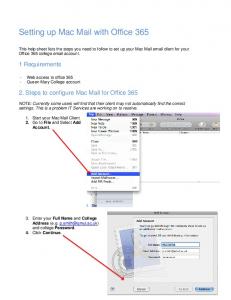
2 Preliminary: Getting ProMoT setup for the first use 2.1 How do I install ProMoT? Usually ProMoT is used from the editor Emacs. Therefore the line (load "/usr/local/lisp/promot/src/emacs/promot") must be inserted into your personal˜/.emacs1 . 1. Open a new terminal window like kconsole from the window manager. Usually there is a control panel in KDE and on this control panel you can find a screen-icon. Click on this icon one time, and you will get a terminal. 2. Type emacs ˜/.emacs1 and hit the return (enter) key. In all following commands we will assume implicitly that you hit return. 3. Move the cursor to the beginning of the file (it may be empty) and type: (load "/usr/local/lisp/promot/src/emacs/promot") . Save the file by the menu bar File > Save or by pressing the keys C-x C-s (this is the Emacs notation for Pressing Control and the “x” key at the same time followed by Control and the “s” key.) (Explanation: the .emacs is a startup-program of 1
If the tilde ‘˜’ seems to be broken on a German (QWERTZU) Keyboard, it is possibly necessary to type the tilde key followed by an space ‘ ’. Tilde is used in UNIX and Linux to refer to your personal home directory instead of typing the pathname all the time.
3
the text editor emacs. It is executed every time, emacs starts. By adding this line, some new entries are added to the menu of emacs to start ProMoT from there.) 4. Exit the Emacs by the menu bar File > Exit Emacs or by pressing C-x C-c. At the next start of Emacs, ProMoT will be available.
2.2 How can I start ProMoT? 2.2.1 From the console 1. Use your Terminal window or start a new one as described in 2.1. 2. type ”/usr/local/lisp/promot/scripts/promot” and ProMoT will get started. 2.2.2 Using emacs 1. Use your Terminal window or start a new one as described in 2.1. 2. Type emacs and emacs starts up. 3. Select in the menu-bar of Emacs: ProMoT>Start ProMoT. 4. The Browser window of ProMoT shows up. Inside Emacs there are now two windows, showing useful information about the ProMoT system: *promot-server* and *compilation*. It is also possible to work interactively with the *promot-server*.
3 Getting Started: A look at the ProMoT GUI Upon starting ProMoT the default (the bare necessities that compromise the program) ProMoT GUI (graphical user interface: i.e. the windows, menus items, scroll bars, etc. that frames the main content that ProMoT presents as a working environment) loads the browser, which is the main window of ProMoT, see Figure 1. The browser contains four menus (File, Class, Select, and Options) with drop down selections allowing the user to find modeling entities, start graphical and textual editors as well as to load and save files. There are two distinct areas of the ProMoT GUI, a browser left panel containing a file tree that shows the class hierarchy with all the modeling entities currently loaded and a browser right panel where, if desired, the currently selected classes .MDL source code can be previewed. (If you do not see the right panel we explain 4
how to view this in a bit). The file tree can be expanded and compacted by clicking the handle buttons to the left of each entity, where subclasses are shown in the subtree of the regarding super-classes. For example the default classes of ProMoT, as shown in Figure 1 are of the Modeling-entity and include: 1. behavioral-modeling-entity > continuous-modeling-entity > > equation > > variable > discrete-modeling-entity > > place > > transition 2. structural-modeling-entity > module > terminal ProMot Browser Browswer Menu Browser Left Panel Browser Right Panel (.MDL Source Code Preview) (File Tree)
Context−Menu
Figure 1: ProMoT Browser Window For the first time user the most important modeling entities are located in the subtree of the structural-modeling-entity > module. The file tree also has a context-menu (which can be viewed upon right-clicking) for each entity within it and is used for starting most editing actions. To go to the structural-modeling-entity > module:
5
1. Click the handle button to the left of the folder icon of structural-modeling entity 2. Now there are two basic classes in view, module and terminal and no modelingentities defined. 3. To view the context-menu right click on the modeling entity 4. The ProMoT browser enables the user to view either just the left file tree panel or both the left file tree panel an the right source code panel. To switch back and forth between modes click on the ProMoT browser menu > Options and select the check-box Show Quickview. With this option enabled it will preview the corresponding .MDL source code in the right panel of the ProMoT browser of the currently selected class. ProMoT models are written in .MDL, however this is all that is important for purposes here within.
4 Building Your First Model: toymodel 4.1 Creating Submodules The following is a step-by-step tutorial to creating a simple hierarchical model using ProMoT. The name of the whole model will be toymodel and will contain the submodules (subclasses) cell, whole model, and nucleus. which represent certain levels of a cell that are commonly examined when modeling a signal transduction pathway. 1. Start ProMoT and expand the structural-modeling-entity with the left handle button to view the module subclass. 2. Right click on module and click on Add Subclass, as seen here in Figure 2 . A window pop-ups asking to name the new subclass. Click within the text area of the pop-up window and type in the desired name for the model. (In our case type in: toymodel). 3. Click OK. 4. The naming pop-up window will disappear and a handle button will now appear next to the structural-modeling-entity > module in the ProMoT browser. Click on the handle button to expand the module tree. There you will see the subclass we just added as “toymodel”.
6
Figure 2: ProMoT Browser Window: Adding a Subclass
7
5. One of ProMoTs attributes is its ability to construct and handle models built in a modular style. Modules are attractive in modeling for purposes beyond the scope of this tutorial, but with this in mind let our first example include this approach and let us create the submodules as discussed above: (a) Right click on the toymodel and click on Add Subclass (as done in step 2 above, but under toymodel instead of module) but this time naming the subclass cell. Repeat this step to add the subclasses named whole model and nucleus as well, being sure to right click and add the submodule under the toymodel.
4.2 Saving Files Now let us save things before we get to the building part: 1. First it is recommended to make a folder where you will save all your files from ProMoT. In your home directory (or directory of your choice) make a folder called promot. 2. To make this directory: (a) Open a new shell terminal window (b) Make the directory by typing: mkdir promot (c) Change to that directory by typing: cd promot 3. Now that we have the main directory for all future model and simulation files let us create another directory for the toymodel example we are in the process of building. Using the same shell we just used to create the ProMoT directory, under the /promot]> directory make another directory called toymodel to save all the files associated with this example in: (a) in the /promot]> directory type: mkdir toymodel (b) change to that directory by typing’: cd toymodel 4. Now that we have a directory for this project within our ProMoT folder now we are ready to save the files: (a) Click on the Superclass (i.e. toymodel ) of all the submodules (i.e. cell, nucleus, whole model ) and go to the Select menu. From the Select menu chose: Select > Select Subclasses. 8
(b) Then go to: File > Save Selected and save the .mdl file in the toymodel directory just created named toymodel.mdl. (c) Then select each subclass separately and save them each separately in the same directory. 2 (d) One may also want to delete a class or load a different class into ProMoT. Since we have not started building a model yet, lets try this to become familiar with the process. i. To delete a model: (let us delete cell as an example) Click on the cell module in the Browser left panel, then right click on it and from the Context-Menu select Delete. The cell module will then dissappear from the ProMoT Browser but its corresponding .MDL source code will still be in the toymodel directory you saved it in previously. Now lets reload the file. ii. To load a model: From the ProMoT Browser Menu go to: File > Open and go to the directory toymodel directory and select the cell file and then click on Open. The cell module will then load back into the ProMoT user interface.
4.3 Loading ProMoT Library Elements Before we begin the building process we need to load the building components of ProMoT, this is called the ProMoT library: To do this you will need an initial library file from ProMoT 3 which includes logical components for building the models, such as the gates, compounds, and connecting elements. 1. Once you have this file load it into ProMoT by going to File > Open >> struct-ana-library.mdl (in our case this is the name of the library) and selecting the file and then clicking on Open. 2. Under the Browser left panel in the module the subclass struct-library will appear 3. Click on the handle button to the left of the struct-library to expand the library. There you will see subclasses of the library which are composed of the building blocks of ProMoT. (i.e. compound, gates, input, not, output, struct-adapter) 2 Note:
This step is not necessary but makes working with individual parts of the model easier until the whole thing is complete. 3 typically at: /usr/local/lisp/promot/kb/SignalTransd/structure/
9
Figure 3: ProMoT Browser with Expanded Struct-Library and ProMoT Visual Editor for Cell Module
10
The main subclasses of the ProMoT follows:
library to build a logical model are as
(a) Compound: To model logical states. Compound contains some common molecular classifications of certain species in a signaling network. These can be viewed by expanding the compound class by clicking on its corresponding handle button.(i.e. adapter (adapter protein), gpro (gprotein), kinase, phosphatase, receptor, transfactor (transcription factor) etc. Note that compounds can not be directly connected, and you need (at least) one element of the class gate between any 2 compounds. Examples will be discussed in section 4.4. (b) Gates: Gates include the logical connecting components of the network for describing certain reactions and are based off of common boolean logic and operators. i. Activ: A single arc denoting the influence of one element on another is made via an ACTIV (activating gate); if the effect is negative, a NOT (see below and Fig.4(b)) should be additionally included. ii. AND Allow the connection of 2 or more compounds together and follow the “all or nothing” normal logic of an AND gate (see Fig.4(e)). We have built AND gates that allow up to 6 input species, however larger gates can also be built. iii. OR: A logic OR connection can easily be implemented using nodes (Fig.4(c); the inclusion of nodes is described in 4.4 and Fig. 6), alternatively an OR gate (Fig.4(c)) can be used to allow the connection of several species to one gate, if e.g. one wants to replace an AND gate by an OR gate. iv. SOMEHOW These gates act as a gate where the connection is not completely clear and allow to model incomplete truth tables. [2] (c) NOT The NOT gate is used to represent an inhibitory effect on a compound. It must be used in place before any activating reaction gate (i.e. before an Activ, AND, OR, or SOMEHOW gate, see Figs.4(b),4(f)). (d) Input Represents an input to a compound. All compounds that have no prior activating (or inhibiting) reaction to them must be connected to a input component (via an Activ). (e) Output Represents the output of a compound (f) Struct Adapter Allows to connect a node to a terminal
11
a
a not
activ and
b
b
(a) ACTIV
a
(b) NOT
a2 a
a2
activ2
activ
or
b
b
(c) OR (using a node)
a
(d) OR (using a gate)
a
a2
a2
a3
not and
and
b
b
(e) AND
(f) Combination of activations and inhibitions in an AND gate
Figure 4: Implementation in ProMoT of basic logical connections. 12
4.4 The Building Process We are going to be building the figure seen in Figure 5 which corresponds to “toymodel”. [3] This model represents a simple modular example of a cell signal transduction pathway. There are three main modular levels to toymodel: (a) whole model Represents the overlay of the whole cell and two extracellular inputs representing different possibilities of ligand binding to the cells receptors. (b) cell Comprises the main inter-cellular signal transduction reactions that occur upon ligand binding to the cells receptor, down to (and including the nuclear phenomena) (c) nucleus Represents the subsequent events that lead up to gene transcription, expression or proliferation Let us begin the building process:
input2
input1
input1__r1
lig1
lig2
input2__r2
cell r1__a1 r1
r2
not notr1_r2__a2 a1
a1__ph2 a2
not_ud
a1_notph1__k1
k1
and_2_2 ph2 k1_k3r__k3p1
k2
inputk3r inputk3r__k3r ph1
k3p1__ph1k3p1
k3r
k2_k3r__k3p2
k3p2 input1
input2
k3p1_k3p2__tf1 nucleus
tf1 tf1__geneexp geneexp
Figure 5: Toymodel described in [3]. See a larger version in the appendix 8 (a) Click on the cell module of the toymodel and once it is highlighted right-click on it to view the context-menu. Then select Visual Edit. This brings up a new window in ProMoT displaying the ProMoT Visual Editor, or the working panel of ProMoT. (b) There are two main areas to the ProMoT Visual Editor 13
i. The left area where there are tabs for: Modules, Terminals and Superclasses. ii. The canvas or template area on the right where the model is built. (c) Click on the Modules tab. There you should see some of the building components from the struct-library file. But one may want to add more elements here for easy use. To do that: i. From the ProMoT Browser Left Panel simply drag and drop the desired component into the Modular tab area of the Visual Editor. ii. If you would like that component to always load upon opening of the Visual Editor by default, click on that component within the Visual Editor Module, then right-click and select Default Class. iii. If you want to delete a certain component from loading by default into the Visual Editor select the component, right-click and select Remove Default iv. Finally, if you want to delete the component from the Modular tab area altogether, select the component, right click and select Delete (d) Now, to build the model you just drag and drop components from the module tab area into the canvas part of the ProMoT Visual Editor. For instance, in our example of the cell module we have a receptor named r1. To add this receptor: i. Click on the receptor compound in the module tab and drag it onto the cell canvas. ii. To rename the component, within the model right click on the component and select properties. Under Slot name type in the desired name (in our case r1 and click on Set then Close. (e) Next connect compounds together in the network by different gates. Let us for example make the connection from r1 → a1: i. Drag a adapter (protein) onto the canvas and rename it to a1 ii. Drag a activ onto the canvas and rename it r1 a14 iii. Now connect the input terminal of the activ gate to the terminal connection (the little blue circle) in r1 and then connect the output terminal of the activ gate to the terminal connection (little blue circle) of a1. iv. Our first connection has been made. You should have something similar to 6(a). 4 the
names given to the gates can be chosen freely and have no importance
14
(f) Now as one can see in Figure 5 more than one compound is attached to r1. Therefore we need to make it possible to add more than one connection to its terminal. To do this: i. Click on the terminal connection (the blue circle) of the compound (here r1) or on the link (blue line) connecting it to the active. ii. Then right click and select Insert Node. You should have something similar to 6(b).
r1
r1
r1__a1
r1__a1
a1
a1
(a) r1 activates a1
(b) addition of a node to add further connections
Figure 6: First steps in setting up the toy model. The final model is displayed in7. (g) You can move any of the elements around on the canvas, for visually more appealing positions, by selecting it and moving it with either your mouse, or with the arrow keys from your keyboard. (h) Now let us add the second receptor, r2, a2, and the notr1 r2 a2 AND gate: i. ii. iii. iv.
Drag a not gate onto the canvas. 5 Drag a and-2 gate onto the canvas and name it notr1 r2 a2 Drag another adapter onto the canvas and name it a2 Drag another receptor onto the canvas and name it r2
(i) Connect them together by clicking r2 and then click and drag your mouse from the r2 terminal connection to one of the two inputs of the and-2 gate. 5 as
for the gates, the name of the not elements have no relevance
15
(j) As mentioned before the not gate is used to represent an inhibitory effect. Click on the input of the not and then click on its terminal connector and click and drag to connect it to the node of r1. Then click on the not again and click on the output terminal and click and drag it to connect to the other input of the and-2 gate. (k) Now click on the output terminal of the and-2 gate and then click and drag this to the a2 terminal connector. (l) Continue building the cell model in this fashion until it looks like Figure 7 below, remembering to name the elements before connecting them and also adding nodes to compounds that you would like to add more than one connection to. Also, be sure to save the model through the Visual Editor periodically by selecting Model > Save.
Figure 7: Building a Model: ProMoT Visual Editor: Cell Module (m) Now you need to add the input and output components to the model. If this were a single (non-modular) model one could use just the input and output library components, however because we want our input components to come from another module we need to tell ProMoT this and add a terminal structure input. To do this: i. Click on the input1 r1 activ gate and then right click and select Terminal Connections > Propagate input. Rename the terminal connection to input1. 16
ii. When you have added both inputs to the model save the model through the Visual Editor as explained earlier and then close it by clicking on the X on the upper-right hand corner. Do not worry about the connection to the Nucleus Module at this point (we will get back to that). (n) Now back in the ProMoT Browser select the cell module and save it to its own file by selecting File > Save Selected and overwriting the cell.mdl file you first created. This makes it so, later in time, you can load the file independently if so desired. (o) Next, select the nucleus module and open it in the Visual Editor as you had previously done with the cell module. (p) Build the model as done in previous steps according to the nucleus module seen in Figure 5 being sure to save the file in both the Visual Editor and the ProMoT Browser. (q) Next, click on and open whole model in the Visual Editor and add the two input elements lig1 and lig2. (r) Now we need to connect the cell module to this whole model module. To do this: i. Within the ProMoT Browser click on the cell module and drag and drop it into the Modules tab area of the Visual Editor (as done previously to add library components to the Visual Editor). ii. Then just as you build the model, drag the cell onto the canvas and connect the input terminal connection from lig1 to the first input of the cell and the input terminal connection from lig2 to the second input of the cell. iii. Save the file in the Visual Editor as well as in the ProMoT Browser. 6 You will not see the circular icon of the cell that is in Figure 5, but rather just a white box with the modular name cell typed in blue font on its inside. Until you design your own icon to implement into the code this is what it will look like, and this topic is beyond the scope of this tutorial. (s) Next we need to add the nucleus module to the cell module. (t) As done before, open the cell module to the Visual Editor from the ProMoT Browser. 6 Note:
17
(u) Then drag the nucleus module from the ProMoT Browser into the Modules tab area of the Visual Editor. (v) Then drag the nucleus module into the cell canvas and connect the corresponding connections to its input terminal connections. (In our case: k3p2 to nucleus input2 and k3p1 to nucleus input1). (w) Save the file in both the Visual Editor and ProMoT Browser. (x) Finally, save the whole superclass toy model again with all subclasses selected. (Click on the toy model, click on Select > Select Subclasses, and then click on File > Save Selected and overwrite the toy model.mdl file saved previously.
5 ProMoT Extras 5.1 ProMoT Properties While building logical models there are different properties that are often useful for describing the characteristics of the model. ProMoT has implemented some of these concepts into properties of the model, these properties are considered “variables.” These properties include the following: 1. time:This variable is the parameter determining the time-scale for the reactions. These can be labels either 1,2, or 3; 1 being the default value and earliest (or fastest) time event and 3 being the slowest event. 2. defval: This is to set the logical default value of a compound, and in this case since we are using logical models they can be set as either 1 or 0. By default ProMoT sets the default value to nothing. 3. conf: Degree of Confidence. This variable is used to set a level of how confident or well supported a certain reaction is. One being the most established. 4. a: Level of activation. This parameter is default 1, and can be modified to encode multilevel logical operations. For example, in the toymodel (see Fig. 5), tf1 reaches a level 2 if both k3p1 and k3p2 are active. This is set up in ProMoT via a gate of the class AND where the output has a= 2 (see Fig. 8). These properties can be changed in the Visual Editor of ProMoT by selecting the specific reaction gate, then right-clicking on it and selecting “Edit Variables”
18
input2
input1
k3p1_k3p2__tf1
tf1 tf1__geneexp geneexp
Figure 8: Properties like the multilevel variable a can be edited in the variable editor.
19
5.2 Documentation in ProMoT The construction of signaling networks often leads to large complex models. One of the most important things to do while building these models is to keep track of the references of where the data supporting the architecture of these models is coming from. ProMoT allows this to be implemented while building the model in the Visual Editor. 1. When in the Visual Editor select the reaction of your choice 2. Right-click on the reaction and choose Properties 3. Under the Slot class selection area there is an area labeled Documentation, click so the cursor becomes active there and type the desired documentation 4. Then click on Set 5. Then click on Close
6 Visual Explorer The Visual Explorer is an additional entity of ProMoT . To get to the Visual Explorer: • Within the ProMoT Browser Left Panel select the model of your choice. • Right-click on the model and from the Context-Menu select Visual Explorer. • While loading an information window appears. • After a certain time the Visual Explorer will pop-up (depends on the size of the network). The Visual Explorer is used for creating and manipulating different graphical representations of a network. For this purpose, the concept of Visual Scenarios are introduced. A visual scenario is a set of visual mapping functions for changing visual properties of the network (layout, display) and defines adequate user interactions. Therewith, convenient and fast switching between different visual settings is feasible. Almost all visual properties of the network and its parts can be altered, e.g. color, size, line type. For setup a visual scenario:
20
• Middle-click on the model within the Visual Explorer and from the ContextMenu select Edit Scenario. . . • Select a new scenario in the Popup-Menu. • Or alter the current scenario by clicking on Define. • There is also a Popup-Menu at the bottom line of the Visual Explorer window where a new scenario can be choosen.
6.1 Properties Properties like the multilevel variable or the visibility variable can be edited in the variable editor (how to use the variable editor see . . . ). The parameter a (level of activation), is default 1 (level 1), and can be modified to encode multilevel logical operations. The parameter ContentVisible (visibility of the content), is default 1 (visible), and can be used . . . . lig1
lig2
cell r1
lig1
r1
r2
a1
r2
a1 a2
a2 ph2
k1
ph2
k1
k2 ph1
lig2
cell
k2
k3p2
k3p1
ph1
nucleus
k3p2
k3p1
nucleus
tf1
geneexp
Figure 9: Alternative visual scenario towards a more abstract representation. Proteins have a uniform color, connection lines are orthogonalized, and the border of cell and nucleus are de-emphazised to draw the attention to both logical operations and connections. Additionally, to illustrate the visibility property, in the right figure the visibility of the module nucleus has been set to 0 and that of the logical gate and 2 2 to 1 (for illustration purposes the gate and 2 2 is displayed enlarged).
21
6.2 Visual Scenarios In the visual explorer different scenarios are predefined, e.g. “Logical Network”, “Connectivity” or “Semantic Distance”. These are common scenarios that have the following functionalities • Logical Network .... • Connectivity Each entity is ranked by a connectivity value based on the link structure (incoming and outgoing links). Hence, connectivity is a property of graphs and is used for analysis in graph theory. Here, the connectivity value is encoded by a color gradient. • Semantic Distance Semantic distance means the distance from a focused entity to another entity in the network structure. Semantic distance is encoded by color. This scenario is interactive (user has to set the focus entity and eventually a second focus entity). Furthermore, the Visual Explorer is more appealing for publication, exportation, and printing. For an overview of interaction pattern, shortcuts and modifiers, please refer to Table 1 in the appendix.
7 Exporting the Models There is currently no standard for logical networks (note that SBML only supports kinetic models). There has been recently an initiative to define a standard for boolean networks (GinML, see [4]) which is, however, still not established. Therefore, we have so far only implemented two formats: one for CellNetAnalyzer (CNA) [2] and one in an alternative matlab formalism. New formats, however, can be easily implemented. To export the logical ProMoT model with its corresponding graphic file and mathematical components,open the model of your choice in the Visual Explorer as discussed previously. Then, right click on the model and select “Output Logical Model” from the menu, choose the format, and save it to the directory of your choice. To get CellNetAnalyzer, go to http://www.mpi-magdeburg.mpg.de/projects/cna/cna.html. In order to perform analyses as those from[2], do not to check the “Export Boundary Compounds”. Besides, the “Simples Names” option will export quite compact names.
22
References [1] M. Ginkel, A. Kremling, T. Nutsch, R. Rehner, and E. D. Gilles. Modular modeling of cellular systems with promot/diva. Bioinformatics, 19(9):1169–1176, June 2003. http://bioinformatics.oxfordjournals.org/cgi/content/abstract/19/9/1169 . [2] S. Klamt, J. Saez-Rodriguez, J. Lindquist, L. Simeoni, and E. D. Gilles. A methodology for the structural and functional analysis of signaling and regulatory networks. BMC Bioinformatics, 7(56), 2006. http://www.biomedcentral.com/1471-2105/7/56, [3] J. Saez-Rodriguez, S. Mirschel, R. Hemenway, S. Klamt, E. D. Gilles, and M. Ginkel. Visual set-up of logical models of signaling and regulatory networks with promot. submitted. [4] A. Gonzalez and A. Naldi and L. Sanchez and D. Thieffry and C. Chaouiya GINsim: A software suite for the qualitative modelling, simulation and analysis of regulatory networks Biosystems 2,91-,100,2006.
23
8 Appendix 8.1 Example Model 8.2 Visual Explorer Shortcuts and Modifiers Operation
Shortcut
Description
Menus Open global menu Open node menu Open edge menu
Click middle button Click right button on entity Click right button on entity
Opens the global context menu Opens the node context menu Opens the edge context menu
Navigation Mode: Pan+Zoom Zoom in Hold down left button + Drag right Zoom out Hold down left button + Drag left Pan Hold down left button + Shift + Drag
Zoom in the network Zoom out the network Move the network
Navigation Mode: Hierarchy Zoom Zoom in Click left button on entity Zoom out Click left button on entity Fit network on screen Click left button + Shift
Zoom to focused entity in hierarchical steps Zoom to focused entity in hierarchical steps Zoom out the whole network to fit on screen
Navigation Mode: FishEye Zoom Zoom in Click left button on entity Zoom out Click left button on entity + Shift Navigation Mode: Focus Zoom Zoom to Click left button on entity
Minimal zoom to focused entity
Navigation Mode: Detail+Overview Pan Click left button on gray box + Drag Zoom Click left button on handle of gray box + Drag
Move the network Zoom in or out the network
Editor Mode: Node Move Resize (all) Resize (border)
Click left button on entity + Drag Click left button on handle + Drag Click left button on handle + Shift + Drag
Move node inside bounds of parent node
Editor Mode: Edge Move handle
Click left button on handle + Drag
Move edge handle
Scenario Mode: Semantic Distance Show Sem Dist Click left button on entity Shortest Path (two) Click left button on two entities + Shift Shortest Path (all) Click left button on two entities + Ctrl
Show Semantic Distance for focused entity
Table 1: Shortcuts and modifiers used in the Visual Explorer.
24
input1
input2
input1__r1
lig1
notr1_r2__a2 a1
a1__ph2 a2
a1_notph1__k1
k1
and_2_2 ph2 k1_k3r__k3p1
k2
inputk3r inputk3r__k3r ph1
k3p1__ph1k3p1
k3r
k2_k3r__k3p2
k3p2 input1
input2
k3p1_k3p2__tf1 nucleus
tf1 tf1__geneexp geneexp
25
r2
not
Figure 10: Toymodel described in [3].
cell r1__a1 r1
not_ud
lig2
input2__r2