Tutorial on Verification of Distributed. Cache Memory Protocols. Steven M.
German. IBM T.J. Watson Research Center. Formal Methods in Computer-Aided
...
Tutorial on Verification of Distributed Cache Memory Protocols
Steven M. German IBM T.J. Watson Research Center Formal Methods in Computer-Aided Design 2004
1
FMCAD Tutorial November 12, 2004
Outline
1. Modelling and verification of memory protocols at the architecture level • An example of an architecture-level model 2. Experiences with verifying complex protocols • Latest generation mainframe • Formal design in the memory protocol for the ASCI Blue supercomputer 3. Formal Design of hardware implementations • Developing hardware implementations from guarded command specifications
2
FMCAD Tutorial November 12, 2004
Part 1 Modelling and Verification of Memory Protocols
3
FMCAD Tutorial November 12, 2004
Mainframe Server System Ring Node 0
Node 1
P
P
L2
P
P
L2
P
P
SC
P
P
SC
P
P
P
P
P
P
P
P
Mem
Node 3
Mem
Node 2
P
P
L2
P
P
L2
P
P
SC
P
P
SC
P
P
P
P
P
P
P
P
Mem
Mem
The system has four nodes connected on a bidirectional ring. • Processors (with individual L1 caches) • A shared L2 cache • Memory (L3) • System Control Element (SC): Provides coherent access to data across nodes 4
FMCAD Tutorial November 12, 2004
Ring Protocol Model Node 0
Node 1
INV
M5
IM EXCL
M6
Node 3
Node 2
INV
INV
M4
M7
Abstract model shows states and messages for one cache line. Transitions are larger than a clock cycle. 5
FMCAD Tutorial November 12, 2004
Themes of This Talk
• Why abstract protocol models are needed • How to make abstract models of memory system hardware • How to assure the hardware is consistent with the protocol model – emerging work
6
FMCAD Tutorial November 12, 2004
Traditional Approach to Verification in Industry
• Traditional view is that the RTL serves as the most precise statement of the design. – Design problems are worked out at RTL level • Traditional verification is based on random simulation of completed parts of the RTL • Simulation expert guides the simulation toward critical tests, using knowledge of the design.
7
FMCAD Tutorial November 12, 2004
Problems with Traditional Approach
• Simulation of an entire system gives poor coverage. Errors escape random simulation of HDL! • The implementation is usually too large to check directly by model checking, • Compositional model checking of the implementation is difficult because of the need for correct specifications of the components. • Many of the errors found in testing protocol hardware are errors in distributed computing. – These errors should be found earlier!
8
FMCAD Tutorial November 12, 2004
Integrating Formal Methods Into the Design Process Level 1: Formal verification of completed parts of RTL design • Problem of scale: Global properties cannot be formally verified at RTL level! Level 2: Architectural Verification • An abstract model of the design is created and verified by a formal methods expert. Designers make limited use of model. The model is used to derive specifications for system simulation. Level 3: Formal Design • A formally verified model serves as a guide for RTL development. Formal Design of a hardware protocol was first explored in IBM on the shared memory adaptor cache protocol for ASCI Blue. The ASCI Blue RTL was completed ahead of schedule and with very few errors. 9
FMCAD Tutorial November 12, 2004
Tutorial Cache Coherence Protocol – Very High Level View Invalidate Sharer Request
Client
Home
InvalidateAck
Grant Sharer
Four classes of messages Type 1 Request to Home node Type 2 Invalidate a remote cache Type 3 Invalidate Acknowledgement Type 4 Reply (Grant) from Home node
10
FMCAD Tutorial November 12, 2004
Channel Assignments Channel 1 Client
Channel 2
Home
Channel 3
Three FIFO message channels between each pair of nodes: Channel 1: Type 1 Request to Home node Channel 2: Type 2 Invalidate a remote cache Type 4 Reply from Home node Channel 3: Type 3 Invalidate Acknowledgement Why three channels? • Three channels is enough to avoid deadlock • Types 2 and 4 on same channel to maintain coherence. 11
FMCAD Tutorial November 12, 2004
A Race Condition
Client 1
ReqEx
GrantEx
Client 1
GrantEx
Client 1
Home Inv
Client 2
Home Ex 1
Client 2
Home Ex 1
GrantEx Client 1
Invalidate
Home Ex 1
GrantEx Client 1 InvalidateAck
Client 1
GrantEx
Home Ex 1
Home Ex 2 12
ReqEx Client 2
ReqEx Client 2
ReqEx Client 2
GrantEx Client 2
FMCAD Tutorial November 12, 2004
Detailed Model – Represents Hardware Architecture - Each node acts as both home and client - Each node has Local Unit, Home Unit, Remote Unit - Refinement of message processing into phases: Receive message, Process, Send reply - Multiple addresses - Multiple requests active at a node at same time - Memory hierarchy: Main Memory and Cache - Protocol shows movement of data - More detail in messages - IO channels refined - Nodes can send messages to themselves (Request, Invalidate)
13
FMCAD Tutorial November 12, 2004
Structure of a Node Processors
Type 1 Requests
Local Unit
Outchan 1
Inchan 1
Type 2 Invalidate
Home Unit Inchan 2
Outchan 2 Type 4 Grant
Remote Unit
Outchan 3 Type 3 Inv Ack
Inchan 3
Directory
Cache
14
Memory
FMCAD Tutorial November 12, 2004
Murphi Developed by David Dill, et al, Stanford University A Murphi model consists of • Global state variables • Transition rules condition ==> body Data types: Boolean, Enumerated, Integer Subrange, Arrays, Records A model is executed by applying one transition at each step. A transition can be executed at a step if its enabling condition is true Interleaving or Unity semantics A model can specify transitions compactly using function and procedure definitions. 15
FMCAD Tutorial November 12, 2004
States of the simple model type message: enum{empty, req_shared, req_exclusive, invalidate, invalidate_ack, grant_shared, grant_exclusive}; cache_state: enum{invalid, shared, exclusive}; client: 1 .. num_clients; -- state of home node: var home_sharer_list, home_invalidate_list: array[client] of boolean; var home_exclusive_granted: boolean; var home_current_command: message; var home_current_client: client;
16
FMCAD Tutorial November 12, 2004
-- state of caches in client nodes var cache: array[client] of cache_state;
-- message channels -- requests to home var channel1: array[client] of message; -- messages to client var channel2_4: array[client] of message; -- invalidate acks to home var channel3: array[client] of message;
17
FMCAD Tutorial November 12, 2004
Detailed Model – Node node_type: record local_requests: array[addr_type] of boolean; home_requests: array[addr_type] of home_request_type; remote_requests: array[addr_type] of remote_request_type; -- NOTE requests are indexed by address -- input channels inchan: array[channel_id] of message_buf_type; -- output channels outchan: array[channel_id] of message_buf_type; directory: directory_type; cache: cache_type; memory: memory_type; end; 18
FMCAD Tutorial November 12, 2004
Detailed Model – State of Processing Units status_type: enum{inactive, pending, completed}; home_request_type: record source: node_id; op: opcode; data: data_type; invalidate_list: node_bool_array; status: status_type; end; -- a type for remote unit. remote_request_type: record home: node_id; op: opcode; data: data_type; status: status_type; end; 19
FMCAD Tutorial November 12, 2004
Detailed Model – Message Types
message_type: record source: node_id; dest: node_id; op: opcode; addr: addr_type; data: data_type; end; message_buf_type: record msg: message_type; valid: boolean; end;
20
FMCAD Tutorial November 12, 2004
Complete Model
• Complete model is in Appendix A. • Joint work with Geert Janssen, IBM
21
FMCAD Tutorial November 12, 2004
Defining Transitions Transitions should be chosen to correspond to atomic operations in the hardware. • Each operation in the hardware should only see the state before or after an atomic action. • Atomic actions may take several clock cycles in the hardware. How do we know the hardware implements a set of atomic operations? • Designer intent – Memory system hardware often has natural atomic operations. – Atomic operations may be more common in memory systems than other hardware such as processor pipelines. • We must design the hardware implementation to make the atomic operations verifiable. 22
FMCAD Tutorial November 12, 2004
Ordering of Transitions
• The model should generate all orderings of the atomic actions that are possible in the hardware. • The orderings of actions are precedence relations: Tr2 cannot preceed Tr1 • Introduce ordering variables in the model: var Tr1_done: boolean; Tr1:
guard1 ==> begin
. . .
Tr2:
guard2 & Tr1_done ==>
Tr1_done := true; end;
begin
. . .
end;
• The model should conservatively overapproximate the orderings of actions in the hardware (for checking safety properties). 23
FMCAD Tutorial November 12, 2004
Points of Coherence The tutorial example has a single point of coherence (home node) for each address.
Some large commercial servers use broadcasts and have a hierarchy of points of coherence: • A cache in an exclusive state • Caches in a shared state • Main memory Rules for overlapping requests are complicated in these protocols.
24
FMCAD Tutorial November 12, 2004
Phases in Verification of Cache Memory Protocol
• Message Fabric • Coherence Protocol
25
FMCAD Tutorial November 12, 2004
Verification of Message Fabric
• Absence of deadlock • Absence of buffer overflow • Liveness properties Usually need to use a multiple-address model because of resource contention. For these properties, we model the arbitration scheme of the message fabric. Message fabrics can often be analyzed independently from the coherence protocol. Proof methods: • Manual proofs • Quantitative model checking for buffer sizes • Model checking on fabric model (abstract details of coherence)
26
FMCAD Tutorial November 12, 2004
Message Fabric and Arbitration
A
Arbiter
Processors
Local Unit Inchan 1
A
Outchan 1
A
Outchan 2
A
Outchan 3
Home Unit Inchan 2
Remote Unit
A
Inchan 3
A
A
A
Directory
Cache
Memory
27
FMCAD Tutorial November 12, 2004
A Simple Protocol
Node 0
Node 1
A single FIFO queue in each direction Protocol actions 1. Send Request 2. ¿ Receive Request; Send Reply À 3. Receive Reply 28
FMCAD Tutorial November 12, 2004
Avoiding Deadlock
Node 0
Node 1
• Requests on solid lines • Replies on dotted lines Absence of deadlock can be shown with a simple proof using case analysis.
29
FMCAD Tutorial November 12, 2004
Quantitative Model Checking Explicit or symbolic model checkers can be easily modified to report the maximum value of a numeric variable over the reachable states. A typical use: Build an abstract model to analyze buffer sizes (prevent buffer overflow). • Define a model where the states are the number of messages in each buffer. • Quantitative model checker reports the maximum occupancy for each buffer.
30
FMCAD Tutorial November 12, 2004
Properties of Coherence Protocol
• Coherence “If a cache has a copy of the data is marked Exclusive, then no other cache has a copy.” • Data freshness “All cached copies of the data have the most recently written value.” Note: Memory may have a stale value.
• Note: Ordering properties of memory models are often implemented within processors.
31
FMCAD Tutorial November 12, 2004
Part 2 Experiences with Verification of Complex Protocols
32
FMCAD Tutorial November 12, 2004
Model Checking the Mainframe Server Protocol
• Subtle errors were found by model checking • Errors found by model checking led to
Major Changes in design of protocol!
– Rules about order of message processing in nodes – Rules about status of memory requests – A planned memory transaction was dropped
Most of the Errors found by formal verification were NOT found by simulation.
33
FMCAD Tutorial November 12, 2004
Model Checking vs. Simulation of Server Protocol Random simulation was applied constantly to the hardware implementation. Model checking was applied to the protocol high level model. • Simulation found a large number of hardware errors • Most of the Errors found by model checking were not found by simulation • In some cases, simulation continued for many months on uncorrected hardware, without detecting known protocol errors. • Compared model checking with random simulation on a Murphi model. Model checking found error in 16 hours. Random simulation did not find error even once in 7 days (≥ factor of 10)
34
FMCAD Tutorial November 12, 2004
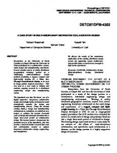
A Shared Memory Protocol for ASCI Blue ASCI Blue - Designed for U.S. Department of Energy - 512 nodes - 8 or 16 processors in each node - High-speed communication network connecting nodes Shared memory protocol - Message fabric - Coherence protocol - Migration protocol Joint work with protocol architect Kattamuri Ekanadham
35
FMCAD Tutorial November 12, 2004
ASCI Blue Node
P
Memory
P
P
Network I/O
P
P
Shared Memory Adapter
Network connection to 511 Nodes
At a high-level, the coherence protocol is similar to the German protocol.
36
FMCAD Tutorial November 12, 2004
Migration Protocol Dir Dynamic Home
Req2 Resign Move Req0
Req1 Confirm
Client Static Home
Migration runs concurrently with the coherence protocol. Important Properties • Requests are eventually serviced (liveness). Requests cannot be forwarded forever. • Order in which requests are serviced 37
FMCAD Tutorial November 12, 2004
Design Process for Shared Memory Adaptor
• Formal modelling and verification preceeded VHDL implementation. • Our first approach to using a formal model as a guide for design of the hardware. • The design was developed at three levels of abstraction. 1. High level design 2. Pipeline level design 3. Hardware implementation
38
FMCAD Tutorial November 12, 2004
Micro-architecture Design of the Protocol Hardware The internal structure of a node is a set of dataflow units that send and receive messages on internal communication channels. Channel assignment and deadlock analysis was refined for this level of design. Design was verified by hand proof and by Murphi. A Producer-Consumer protocol to control communication between adjacent dataflow units was designed and verified with Murphi. The VHDL code was verified with VIS.
39
FMCAD Tutorial November 12, 2004
Producer-Consumer Protocol Producer and Consumer must communicate to keep Consumer busy as much as possible without overflowing queue. Consumer needs a variable, unknown amount of time to process each message. Producer needs at least one clock cycle to respond to a request to produce data or stop producing data.
P R O D U C E R
C O N S U M E R
40
FMCAD Tutorial November 12, 2004
Implementation of the Coherence Protocol The hardware design team used the following approach: • Dataflow units were implemented using a high-level notation called vcode. • Vcode macro-expands to synthesizeable VHDL. • The vcode description is much more concise than VHDL. • Communication between dataflow units is built-in to vcode descriptions. Overall, vcode accelerated the design of the hardware. Very few errors were found in the portions of hardware designed with vcode.
41
FMCAD Tutorial November 12, 2004
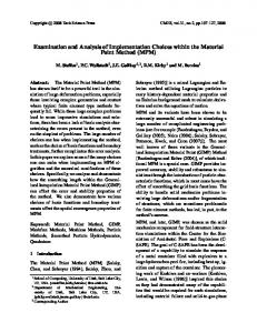
References Formal Design of Cache Memory Protocols in IBM, S. German, Formal Methods in System Design, 22, 2, March 2003, Special Issue on Industrial Practice of Formal Hardware Verification, G. Gopalakrishnan and W. Hunt, guest editors Functional Verification of the z990 Superscalar, Multibook Microprocessor Complex, D. Bair, S. German, W. Wollyung, E. Kaminski, J. Schafer, M. Mullen, W. Lewis, R. Wisniewski, J. Walter, S. Mittermaier, V. Vokhshoori, R. Adkins, M. Halas, T. Ruane, and U. Hahn, IBM Journal of Research and Development, 48, 3/4, May/July 2004, Special Issue on IBM eServer z990
42
FMCAD Tutorial November 12, 2004
Part 3 Formal Design of Hardware from Guarded Commands
43
FMCAD Tutorial November 12, 2004
Project Objectives
• Develop specification methods based on guarded commands for specifying hardware systems. • Develop methods for verifying that a hardware system is a correct implementation of a specification.
44
FMCAD Tutorial November 12, 2004
Related Work
• Jørgen Staunstrup Synchronized Transitions A Formal Approach to Hardware Design (1994) • James Hoe and Arvind, MIT Term Rewriting Systems Hardware Synthesis from Term Rewriting Systems (1999) • Bluespec, Inc. (2004) Hardware design toolset Differences from previous approaches: - Previous work assumed complete or even synthesizeable specification - We allow hardware designers to use expertise to implement the specification - We verify conformance of implementation to specification 45
FMCAD Tutorial November 12, 2004
An Example
InData1
Valid1
Data1 HasData1 Data3 HasData3
InData2
Valid2
Output
RequestOut
Data2 HasData2
Variables input InData1, InData2, Valid1, Valid2, RequestOut; var InData1, InData2, Data1, Data2, Data3, Output: char; var Valid1, Valid2, HasData1, HasData2, HasData3, RequestOut: boolean; 46
FMCAD Tutorial November 12, 2004
Transitions InData1
Valid1
Data1 HasData1 Data3 HasData3
InData2
Valid2
Output
RequestOut
Data2 HasData2
rule "in1" !HasData1 & Valid1 ==> Begin Data1 := InData1; HasData1 := true; End; rule "in2" !HasData2 & Valid2 ==> Begin Data2 := InData2; HasData2 := true; End; rule "move1" HasData1 & !HasData3 ==> Begin Data3 := Data1; HasData1 := false; HasData3 := true; End; 47
FMCAD Tutorial November 12, 2004
rule "move2" HasData2 & !HasData3 ==> Begin Data3 := Data2; HasData2 := false; HasData3 := true; End; rule "out" RequestOut & HasData3 ==> Begin Output := Data3; HasData3 := false; End;
InData1
Valid1
Data1 HasData1 Data3 HasData3
InData2
Valid2
Output
RequestOut
Data2 HasData2
48
FMCAD Tutorial November 12, 2004
Mapping to Hardware Variables ⇐⇒ Hardware registers Transitions ⇐⇒ Hardware processes or state machines A hardware process can take multiple clock cycles to execute a transition. In hardware, independent processes can be active at the same time. In the example, hardware can implement the communication with serial signal transfers; multiple transfers can overlap in time. InData1
Valid1
Data1 HasData1 Data3 HasData3
InData2
Valid2
Output
RequestOut
Data2 HasData2 49
FMCAD Tutorial November 12, 2004
Independent Processes For a process P that implements a transition condition ==> body, we define: RP = {registers read by the implementation of the guard or the body} WP = {registers updated by the implementation of the body} The implementation of the guard must not change the state of the hardware. Processes P1, P2 are independent if W1 ∩ W 2 = ∅ R1 ∩ W 2 = ∅ R2 ∩ W 1 = ∅
Several processes can overlap in time provided they are all pairwise independent. 50
FMCAD Tutorial November 12, 2004
Hardware Protocol for Processes Each process has three hardware signals that describe the state of the process. start : Asserts that the process will start executing on the next state change. active : Asserts that the process was active on the previous state change. done : Asserts that the process finished executing on the previous state change.
Start
Active
Done
Starting values of transition variables. 51
Final values.
FMCAD Tutorial November 12, 2004
Scheduling of Processes
1. If two processes are independent, they can be active at the same time. 2. If two processes are dependent and can be enabled in the same state, an arbiter decides which process to start. 3. If two processes are never enabled in the same state, then for this pair of processes, an arbiter is not needed to decide which process to start.
52
FMCAD Tutorial November 12, 2004
Implementation Relation T:
t
S1 | T
t
S2 | T
Proj
Proj
h H:
h
h
h
h
S1
h S2
T is the specification transition system, transition function t H is the hardware system, transition function h (a clock cycle) var(T) ⊆ var(H) S1, S2 are hardware states where no process is active S1|T, S2|T are specification states, projections of hardware 53
FMCAD Tutorial November 12, 2004
Proof Rules – Informal Idea For each process, we show that the process implements a transition. Rules to show that a process p implements a transition t: 1. Show H |= Startp ⊃ Enabledt 2. Show that when process p is started, it always reaches the Done state in ≤ k steps, for some k. 3. Show
p
H : S1 =⇒ S2 implies t S2|T T : S1|T −→
54
FMCAD Tutorial November 12, 2004
Summary of Proof Rules We can use - Hardware process structure - Independence of concurrent processes - Correspondence between processes and transitions to provide an easy-to-use form of compositional reasoning. Further development will require reasoning about refinement of actions.
55
FMCAD Tutorial November 12, 2004
Pipelining The initial definition of independence is too restrictive: Two transitions cannot concurrently read and write a common variable in a pipeline.
v0
T1
v1
T2
v2
We can write specifications for systems with pipeline concurrency,
w r
T1
T2
w r
w r
and extend our rules to allow pipelined implementations of such specifications. 56
FMCAD Tutorial November 12, 2004
Summary of Tutorial
• Architecture-level modeling and verification can be effective in analyzing the soundness of protocol designs. – Model checking of architectural-level models can find problems that escape both random simulation and formal verification of small components. • Formal models are being developed earlier in the design process. • Formal Design approaches are emerging to guarantee the implementation conforms to a high-level model.
57
FMCAD Tutorial November 12, 2004
Appendix A. Tutorial Cache Memory Protocol Model /* ------------------------------------------------------------------------ */ /* DOCUMENTATION */ /* ------------------------------------------------------------------------ */ /**@file Architecture-level protocol model by Steven German and Geert Janssen Steven German Geert Janssen
4 June 2004 - original write-up (cachei.m) 4 August 2004 - simplified and improved version
*/ /* ------------------------------------------------------------------------ */ /* CONSTANTS */ /* ------------------------------------------------------------------------ */ /**Constants that determine "size" of the problem. */ const num_nodes: 2; /** begin put "> client "; put client; put " prepares invalidate ack for addr "; put addr; put "\n"; assert request.home = home_node(addr) "dest must addr home"; alias msg: outchan.msg do msg.op := invalidate_ack; msg.source := client; msg.dest := request.home; msg.data := request.data; msg.addr := addr; outchan.valid := true; clear request; endalias; endrule; endalias; endruleset; ruleset client: node_id do alias inchan: node[client].inchan[channel2]; msg: inchan.msg; op: msg.op; addr: msg.addr; home: home_node(addr); data: msg.data do -rule "‘client’ receives reply from home" 68
FMCAD Tutorial November 12, 2004
-- have valid data in message input buffer: inchan.valid -- message concerns grant: & (op = grant_shared | op = grant_upgrade | op = grant_exclusive) ==> begin assert msg.source = home "source must match addr home"; alias cache_line: node[client].cache[addr]; local_request_for_addr: node[client].local_requests[addr]; state: node[home].directory[addr][client] do -- update the cache, unless the request was handled locally by -- home = client put "