Check the grid. ... For check boxes, Dynamic Mesh Parameters panel will expand to show relevant inputs. ... (a) Select wall-butterfly from the Zone Names drop-down list. .... DEFINE_GRID_MOTION(moving_arc, domain, dt, time, dtime).
Tutorial: Using a UDF to Control the Dynamic Mesh of a Flexible Oscillating Membrane
Introduction The purpose of this tutorial is to illustrate how to use a user defined function (UDF) to control the dynamic mesh of a generic flow device with a rotating blade and a flexible oscillating membrane. The motion of the rotating blade and the oscillating membrane have a large amplitude which requires the use of local remeshing. The rotation of the blade, the oscillation of the membrane, and the sliding of the nodes along the top wall of the housing are defined and controlled by means of a UDF that utilizes the three macros specific to the dynamic mesh model. In this tutorial you will learn how to: • Set up the dynamic mesh (DM) model for this problem. • Use the three DM-specific macros in a UDF to control the dynamic mesh. • Preview the dynamic mesh before starting the flow computation.
Prerequisites This tutorial assumes that you are familiar with the FLUENT interface and have a good understanding of the basic set up and solution procedures. Some of the basic steps in the setup and solution procedures will not be shown explicitly. You should be familiar with the dynamic mesh model. Refer to Section 11.3: Dynamic Meshes in the FLUENT 6.3 User’s Guide.
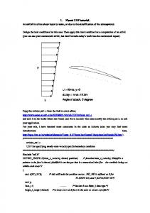
Problem Description A generic flow device with a flexible oscillating membrane beneath it is shown in Figure 1. The valve radius is 0.1 m.
c Fluent Inc. December 11, 2006
1
Tutorial: Using a UDF to Control the Dynamic Mesh of a Flexible Oscillating Membrane
Figure 1: Problem Schematic
Preparation 1. Copy the mesh file butterfly-flex.msh and the source file butterfly-flex.c to your working folder. 2. Start the 2D (2d) version of FLUENT.
Setup and Solution
Step 1: Grid
1. Read the mesh file butterfly-flex.msh. File −→ Read −→Case... 2. Check the grid. Grid −→Check FLUENT will perform various checks on the mesh and will report the progress in the console. Make sure that the minimum reported volume is a positive number.
2
c Fluent Inc. December 11, 2006
Tutorial: Using a UDF to Control the Dynamic Mesh of a Flexible Oscillating Membrane
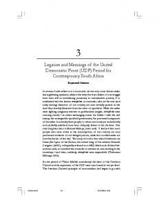
3. Display the grid (Figure 2). Display −→Grid...
(a) Click the Colors... button to open the Grid Display panel.
i. Enable Color by ID in the Options list. ii. Close the Grid Colors panel. (b) Click Display and close the Grid Display panel.
c Fluent Inc. December 11, 2006
3
Tutorial: Using a UDF to Control the Dynamic Mesh of a Flexible Oscillating Membrane
Grid
FLUENT 6.3 (2d, pbns, lam)
Figure 2: Grid Display – Colored by ID Step 2: Models 1. Select the unsteady solver. Define −→ Models −→Solver...
4
c Fluent Inc. December 11, 2006
Tutorial: Using a UDF to Control the Dynamic Mesh of a Flexible Oscillating Membrane
(a) Retain the selection of Pressure Based in the Solver list. (b) Select Unsteady in the Time group-box. (c) Retain the default settings for other parameters. (d) Click OK to close the Solver panel. Step 3: Compile the UDF Define −→ User-Defined −→ Functions −→Compiled...
1. Click the Add... button in the Source Files section to open the Select File dialog box. (a) Select the file butterfly-flex.c and click OK to close the Select File dialog box. 2. Enter libudf-flex as the Library Name. 3. Click Build. A Warning dialog box will appear, asking you to make sure that the UDF source files are in the directory that contains the case and data files.
(a) Click OK button to close the Warning dialog box. 4. Click Load.
c Fluent Inc. December 11, 2006
5
Tutorial: Using a UDF to Control the Dynamic Mesh of a Flexible Oscillating Membrane
The contents of the UDF are listed in the appendix for your reference. The first section (under DEFINE CG MOTION) prescribes a constant angular rotation about the z-axis, and is used to spin the valve. The second section (under DEFINE GEOM) defines a line at y = R = 0.109 m; this line is coincident with the top wall of the housing and guides the nodes as they slide along the top wall. The third section (under DEFINE GRID MOTION) controls the motion of the nodes belonging to the membrane. The initial shape of the membrane is that of a circular arc, and then it moves up and down harmonically. Step 4: Dynamic Mesh Setup The mesh is controlled using a combination of local remeshing with sizing functions and spring smoothing. 1. Set up the controls for spring smoothing. Define −→ Dynamic Mesh −→Parameters...
(a) Enable Dynamic Mesh in the Models group-box. For check boxes, Dynamic Mesh Parameters panel will expand to show relevant inputs. (b) Enable Remeshing in the Mesh Methods group-box.
6
c Fluent Inc. December 11, 2006
Tutorial: Using a UDF to Control the Dynamic Mesh of a Flexible Oscillating Membrane
(c) Set the following parameters in the Smoothing tab. i. Enter 0.3 for the Spring Constant Factor. Setting the value of the Spring Constant Factor causes the tri mesh adjacent to the boundary layer to remain almost unchanged. This avoids skewed cells near the object. ii. Enter 1 for the Boundary Node Relaxation. iii. Enter 0.001 for the Convergence Tolerance. iv. Enter 20 for the Number of Iterations.
c Fluent Inc. December 11, 2006
7
Tutorial: Using a UDF to Control the Dynamic Mesh of a Flexible Oscillating Membrane
(d) Click the Remeshing tab and specify the parameters as follows: Make sure that Size Function in the Options group-box is deselected. Parameter Minimum Length Scale (m) Maximum Length Scale (m) Maximum Cell Skewness Size Remesh Interval
Value 0.00236 0.02 0.65 1
The Minimum Length Scale (m) and Maximum Length Scale (m) can be obtained from the Mesh Scale Info panel. Click Mesh Scale Info... to open the Mesh Scale Info panel. (e) Click OK to close the Dynamic Mesh Parameters panel. 2. Specify the wall-butterfly zone as a rigid body. Define −→ Dynamic Mesh −→Zones...
8
c Fluent Inc. December 11, 2006
Tutorial: Using a UDF to Control the Dynamic Mesh of a Flexible Oscillating Membrane
(a) Select wall-butterfly from the Zone Names drop-down list. (b) Select Rigid Body in the Type list. (c) Select butterfly flex UDF::libudf-flex from the Mesh Motion UDF drop-down list. (d) Retain the default value for Center of Gravity Location as (0,0). The valve motion is defined about its center of gravity (CG) located at (0,0). This is important in the case of rotation. (e) Click the Meshing Options tab and enter 0.002 m for Cell Height.
c Fluent Inc. December 11, 2006
9
Tutorial: Using a UDF to Control the Dynamic Mesh of a Flexible Oscillating Membrane
(f) Click Create. 3. Specify the wall-top zone as a deforming zone. The objective is to allow all nodes located on the top wall to slide along that wall as the tip of the valve moves past it. Thus define a horizontal line and set wall-top zone as a deforming zone.
10
c Fluent Inc. December 11, 2006
Tutorial: Using a UDF to Control the Dynamic Mesh of a Flexible Oscillating Membrane
(a) Select wall-top from the Zone Names drop-down list. (b) Select Deforming in the Type list. (c) Click the Geometry Definition tab. i. Select user-defined from the Definition drop-down list. ii. Select plane::libudf-flex from the Geometry UDF drop-down list. (d) Click the Meshing Options tab.
c Fluent Inc. December 11, 2006
11
Tutorial: Using a UDF to Control the Dynamic Mesh of a Flexible Oscillating Membrane
i. Deselect Remeshing in the Methods list. ii. Retain the default values for other parameters. iii. Click the Create button. 4. Specify the membrane zone as a dynamic zone.
12
c Fluent Inc. December 11, 2006
Tutorial: Using a UDF to Control the Dynamic Mesh of a Flexible Oscillating Membrane
The motion of the membrane and its shadow wall is governed by the function moving arc from the UDF. (a) Select membrane from the Zone Names drop-down list. (b) Select User-Defined in the Type list. (c) Select moving arc::libudf-flex from the Mesh Motion UDF drop-down list. (d) Click Create. 5. Similarly, define the membrane-shadow zone as a dynamic zone. 6. Save the case file (membrane-moving-init.cas.gz). File −→ Write −→Case...
c Fluent Inc. December 11, 2006
13
Tutorial: Using a UDF to Control the Dynamic Mesh of a Flexible Oscillating Membrane
Step 5: Mesh Motion Preview 1. Specify the parameters for the mesh motion. Solve −→Mesh Motion...
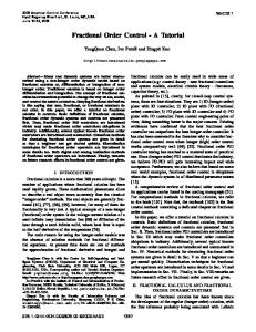
(a) Enter 0.005 s for Time Step Size. (b) Enter 313 for Number of Time Steps (c) Click the Preview button. The valve will move through 90 degrees and assume the position shown in Figure 3.
Grid (Time=1.5650e+00)
FLUENT 6.3 (2d, pbns, dynamesh, lam, unsteady)
Figure 3: Grid Display After Mesh Motion
14
c Fluent Inc. December 11, 2006
Tutorial: Using a UDF to Control the Dynamic Mesh of a Flexible Oscillating Membrane
Summary In this tutorial you modeled an oscillating membrane in a generic flow device with a rotating blade using the dynamic mesh model in FLUENT. The local remeshing scheme was used to define the mesh motion. Dynamic mesh specific macros of a UDF were used to govern the rotational motion of the blade, deformation of the membrane and the sliding of the nodes on the top wall of the housing.
Appendix The contents of the UDF are as follows: #include "udf.h" #define #define
omega R
1.0 0.109
/* rotational speed, rad/sec /* radius of the arc, meters
*/ */
DEFINE_CG_MOTION(butterfly_flex_UDF, dt, cg_vel, cg_omega, time, dtime) { cg_vel[0] = 0.0; cg_vel[1] = 0.0; cg_vel[2] = 0.0; cg_omega[0] = 0.0; cg_omega[1] = 0.0; cg_omega[2] = omega; } DEFINE_GEOM(plane, domain, dt, position) { position[1] = R; } DEFINE_GRID_MOTION(moving_arc, domain, dt, time, dtime) { Thread *tf = DT_THREAD (dt); face_t f; Node *node_p; real alpha, theta, x, ymag, yfull, y; int n;
c Fluent Inc. December 11, 2006
15
Tutorial: Using a UDF to Control the Dynamic Mesh of a Flexible Oscillating Membrane
/* Set/activate the deforming flag on adjacent cell zone, which /* means that the cells adjacent to the deforming wall will also be /* deformed, in order to avoid skewness. SET_DEFORMING_THREAD_FLAG (THREAD_T0 (tf));
*/ */ */
alpha = omega * CURRENT_TIME; theta = 2.0 * alpha + 3.0 * M_PI / 2.0; begin_f_loop (f, tf) { f_node_loop (f, tf, n) { node_p = F_NODE (f, tf, n); /* Update the current node only if it has not been /* previously visited: if (NODE_POS_NEED_UPDATE (node_p))
*/ */
{ /* Set flag to indicate that the current node’s /* position has been updated, so that it will not be /* updated during a future pass through the loop:
*/ */ */
NODE_POS_UPDATED (node_p); x = NODE_X (node_p); ymag = sqrt (R*R - x*x) + 0.03; yfull = ymag - 0.1; y = - 0.1 + yfull * sin(theta); NODE_Y (node_p) = y; } } } end_f_loop (f, tf); }
16
c Fluent Inc. December 11, 2006