rent shape, mainly at the switching moments, for the reduction of ripple [5], [14]. ... server. The second approach has been designed to prevent the use of any ...
Two Automatic On-line New Schemes to Compensate the Torque Ripple of Switched Reluctance Machines: With and Without Torque Signal Measurement Luís O. P. Henriques1, P. J. Costa Branco2, Walter I. Suemitsu1 and Luís G. Rolim1 1
COPPE- Univ. Federal do Rio de Janeiro PO box 68504 21945-970 Brasil Laboratório de Mecatrónica – Instituto Superior Técnico - Portugal
2
Abstract. Each day that passes, the electrical drives operation conditions become more demanding. The use of switched reluctance motors (SRM) has magnified sufficiently with the intelligent control strategies improvement for torque ripple minimization. Another important subject is the sensors’ elimination, allowing the equipment price to be reduced. In this work, two new on-line learning control schemes to minimize the torque ripple in SRMs are proposed. The first scheme uses a sensor torque to measure the motor ripple. In the second one, the ripple compensation is designed without sensor neither a torque observer. It uses the error speed signal as an indirect ripple measure. The two algorithms are explained and simulation results are shown to describe and discuss their performance.
1
Introduction
Nowadays, research in control of switched reluctance machines (SRMs) is sufficiently advanced in relation to those techniques used some years ago. Those techniques as speed controllers based in PI controllers [12] and algorithms proposed for torque ripple problem based in the use of torque-current characteristic tables [8, 3] have shown very little flexibility, robustness and not practical to industrial applications. Recent research, however, have shown the success of using real-time techniques to minimize toque ripple in an online basis, using learning mechanisms or not. Some works use complex algorithms that make the update in real-time of the parameters of the controller [1], other ones launch hand of learning methodologies as neural networks[11] and fuzzy logic [9]. These recent SRM control techniques can be essentially classified into three types according to the methodology used: • Conventional • Neural Networks • Fuzzy logic The conventional controller type, who uses a nonlinear model, is updated online using a recursive identification algorithm [13]. Self-tuning algorithms that can adapt its control constants in real-time can ideally minimize the torque ripple in
SRMs. At high speeds and using this technique, the motor performance degrades significantly. The degradation occurring from the excessively long computation time required. Inside of this scope, we also have the optimization of the phase current shape, mainly at the switching moments, for the reduction of ripple [5], [14]. This strategy is based on generating an adequate contour to the currents in order that the addition of the torques generated for each phase is constant and equal to the desired constant torque. For this, it is defined a contour function. Although, the use of these functions possesses some restrictions: 1. The sum of the functions for all the phases has to be always unitary, and; 2. The current has to be capable to follow the contour defined for the function. Therefore, although it is possible the use of diverse shapes for the current, a careful choice must be made based on some criteria. Moreover, it is considered instantaneous the current switching between the phases, which is impracticable for implying a high dI / dt in an inductive phase winding. Another technique used currently is based on neural networks to control the switched reluctance drive [11, 10]. The approach is based on the specification of a profile to the reference torque being denoted by a function like T (θ, I ) . What it proposes is to generate online a look-up table with the inverse relation between torque/current/position learned by a neural network. This is interesting for allowing taken in account the magnetic iterations between phases. However, a disadvantage of this method is that if the initial parameters of the neural-network are bad conditioned, this will influence the learning time of the network, even causing perturbations in the motor torque, which can be critical to the process where the machine is operating. In [6], the proposed fuzzy logic control structure is not dependent upon predetermined characteristics of the machine and can adapt to parameters’ changes. Also, it is robust toward errors in rotor position and avoids negative torque production during the switching. However, the proposed method is based on the assumption that there is a torque sensor permanently connected to the machine, which is not practical neither safe and very expensive. In this work, two new methodologies for compensation of torque oscillations are proposed. These possess a bigger flexibility of operation because of the presence of learning in the compensators and, when discarding the use of a torque sensor, the system becomes more reliable and can reach a low cost. The learning mechanism makes the compensator more independent of the motor characteristics. If the drive system suffers some modification in the load, in the source, or in the speed of operation, the compensator will possess auto regulation ability to customizing the function shape in this new point of operation, searching the desired reduction of the torque oscillations.
2
Neuro-Fuzzy Compensator
In the work developed previously by the authors [4], it has been developed an offline compensation of the phase currents using the neuro-fuzzy algorithm developed by Jang in[7]. Because of this approach (off-line training), always it is
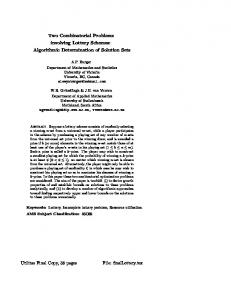
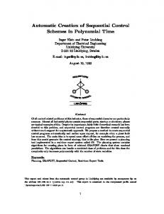
needed to retrain the compensator after any change in the parameters of the machine or in the load [3]. In this work, a new step forward is proposed. Using the same conditions, an online compensation for the reduction the torque ripple is considered for two distinct approaches: using the torque signal and without using this signal. In the first approach, the oscillating part of the torque defined by the total torque subtracted by the average torque is used. In the second approach, the error signal of speed is used as a means to acquire information about the machine’s torque ripple. They are in truth two different training inputs for the compensator, however with an only compensation strategy. A disadvantage of the first approach is the necessity of using a torque sensor. However, this approach can be used before the second one as a first step in the acquisition of the compensator rules. The use of torque sensor in this case is only viable economically if we will be able to make an offline training of the system. The torque sensor is sufficiently expensive to keep it constantly connected to an only system. Most of the research in this subject presents the use of a sensor or a torque observer. The second approach has been designed to prevent the use of any one[6]. It has the advantage that the torque sensor is unnecessary. However, the update signal gotten indirectly from the speed error does not possess as much information on the oscillation of torque of that the proper signal of torque, causing the need of more training time and a learning rate too small to keep the system stable. All these limitations will be shown and discussed in the next sections. As inputs to the compensator shown in Fig. 1, it can be used the speed signal, the rotor position, the phase current, or even the speed error signal. This flexibility is very interesting mainly for the situations where it is not available, through the sensors, all the required learning signals. The overall compensation scheme is shown in Fig. 2. It consists in a neuro-fuzzy system whose output is used together with the output of the traditional PI, modulating its signal and so changing the shape of the pulse currents to ripple reduction. Note the importance of a controller of this type, making possible it’s training through signals indirectly tied with the input signals. For example, the ripple torque oscillation can be used to train the neuro-fuzzy compensator with the objective to produce an oscillating current, or the speed error can be used which presents indirect information about the torque ripple, making possible the exclusion of the torque sensor.
Flag
Signal Error
θ
Iref ω
Neuro-Fuzzy Block
Fig. 1. Neuro fuzzy block details
∆I
In the case where an industrial system is already in operation [2] and if the compensator is to be included, it is necessary to add only the output signal of the compensator to the current output signal of the speed controller. The use of a torque sensor, in this case, is only viable economically if it was able to make an offline training system. The torque sensor is sufficiently expensive to keep it constantly connected to only one machine. Another possibility is to make an online control if it is possible to estimate the motor torque. Also, the elimination of the position sensor can be possible if we can estimate it from the voltage and current signal, and approach in study by us.
θ
1/s filter
Neuro-Fuzzy Block
W ref
+ -
PI Controller
TElet
Iref
+ +
Converter + Motor
W
Fig. 2. Block diagram of the compensation system.
3
Learning and Operation
The compensation block presented in Fig. 2 as the neuro-fuzzy block and shown with more details in Fig. 1 has the following input signals: 1 - Rotor position; 2 - Phase current; 3 - Motor speed; 4 - The learning error signal, which can be the torque ripple signal or the speed error signal (this essentially depends on the strategy to be followed); 5 – and a FLAG signal that makes on or off the compensator training. The compensator output is the step current ∆Ic. The FLAG signal allows at any time to interrupt the learning mechanism without the interruption of the compensation. The neuro-fuzzy system has still the flexibility of change the number and the type of membership functions for each input. In the two test cases effectuated, different neuro-fuzzy systems for each one had been used. For case number 1, 3 membership functions for each input had been used. In case 2, 7 functions had been used. For the two cases, the shape of membership function was set to a gaussian. The choice of the gaussian comes from the fact that it allows that for any input value all rules be activated. Because the compensator has to operate in real-time, each sampling time a composite data set for the 5 inputs is applied to it. The first step of the compensator is fuzzifying the inputs. The membership functions representing the rotor position have the universe of [0-90] degrees, the current functions have the universe of dis-
course of [0-5] A, and finally the universe of discourse of the speed functions is of [0-1000] rpm. After the inputs fuzzification through the gaussian membership functions, one computes an array that will have the degree of the antecedents for each rule. This matrix is search sweeping all the membership functions of the 3 inputs and multiplies all the outputs of the functions. The next step is the defuzzification of the system using the centroid area method for the compensator output result.
4
Simulation Results
4.1
Approach using torque sensor
The results using torque ripple as error signal for updating the compensator, which is computed by subtracting from torque its average value, are shown for speed values: 200 rpm and 50 rpm, this last one to validate the importance of our method for low speeds. The system for 200 rpm was simulated during 0.6 seconds with the learning mechanism and the compensator beginning at 0.2 seconds. Fig. 3 shows the current evolution in one phase. Note how pulse shape begins to be changed by the compensator after 0.2s. The system was shaped using a learning rate of 0.3 and 3 membership functions for each one of the three inputs (current, position and speed). It is observed in Fig. 4 that after the compensator operation, torque ripple oscillations are severely reduced. The least mean square error initiates in this point a sufficiently abrupt falls in its value, as shown in Fig. 5. The speed error signal shows in Fig. 6 that its envelope curve sample is approximately 1 rpm before the compensation. Moreover, after a period of transitory regime this value falls for 0,1 rpm demonstrating that the system is compensating the current. The results for 50 rpm are presented below. The system was simulated during 1.5 seconds and the beginning of the compensation was at 0.6 seconds.
Phase A − 200 rpm − Learning Rate=0.3
200 rpm − Learning Rate=0.3
3
0.5
2.5
0.45
Total Torque (N.m)
Current (A)
2
1.5
1
0.35
0.3
0.5
0 0
0.4
0.1
0.2
0.3
0.4
0.5
Time(s)
Fig. 3 - Phase Current – Learning Rate 0,3 – 200 rpm
0.25 0
0.1
0.2
0.3
0.4
0.5
Time (s)
Fig. 4 – Total Torque – Learning Rate 0,3 – 200 rpm
200 rpm − Learning Rate=0.3
−4
7
x 10
200 rpm − Learning Rate=0.3 1.5
1
5
Speed Error (rpm)
Least Mean Square Error
6
4
3
0.5
0
−0.5
2 −1
1
0 0
20
40
60 80 Number of Points
100
120
−1.5 0
140
0.1
0.2
0.3
0.4
0.5
Time (s)
Fig. 5 – Least Mean Square Error – Learning Rate 0,3 – 200 rpm
Fig. 6 – Speed Error – Learning Rate 0,3 – 200 rpm
For the speed of 50 rpm, it was obtained similar results as for 200 rpm. The current pulses in Fig. 7 begin to be modulated. Torque ripple starts to decrease as shown in Fig. 8, also decreasing the motor speed ripple in Fig. 9. 50 rpm − Learning Rate=0.3 0.12
2.5
0.1
2
0.08
Total Torque (N.m)
Current (A)
Phase A − 50 rpm − Learning Rate=0.001 3
1.5
1
0.5
0 0
0.06
0.04
0.02
0.5
1
0 0
1.5
0.5
Time(s)
1
1.5
Time (s)
Fig. 7 – Phase Current – Learning Rate 0.3 – 50 rpm
Fig. 8 – Total Torque – Learning Rate 0.3 – 50 rpm
50 rpm − Learning Rate=0.3 1.5
Speed Error (rpm)
1
0.5
0
−0.5
−1
−1.5 0
0.5
1
1.5
Time (s)
Fig. 9 – Speed Error – Learning Rate 0,3 – 50 rpm
4.2
Method without torque sensor
For the methodology where the torque sensor is not used, the speed error signal is employed to give information to the compensator about the torque ripple. For this condition, the results for 50 rpm are shown in Fig. 10 and Fig. 11, emphasizing the use of this approach to a low speed range. Phase A − 50 rpm − Learning rate=0.001
50 rpm − Learning rate=0.001
1.8
0.16
1.6
0.14
1.4
0.12
Total Torque(N.m)
Current (A)
1.2 1 0.8
0.1 0.08 0.06
0.6 0.04
0.4
0.02
0.2 0 0
1
2
3
4
5
0 0
Time (s)
Fig. 10 – Phase Current – Learning Rate 0,001 – 50 rpm
1
2
3
4
5
Time (s)
Fig. 11 – Total Torque – Learning Rate 0,001 – 50 rpm
4.3 Considerations about the methodologies For the results presented in Sections 4.1 and 4.2, some previous analyses were needed. At first, the influence of the learning rate value into the compensator system has been analyzed. The learning rate value strongly affects how fast the system learns the “good” compensation. The values initially used had been: 0.001, 0.1 and 1. For 0.001, the training has become excessively slow (Fig. 12 and Fig. 13). For a unity learning rate, the system has become unstable. Therefore, the value of 0.1 for the learning rate has been chosen (Fig. 14 and Fig. 15). How large is the learning rate, faster is the learning. However, a very fast learning can generate the instability found in the case where the learning rate was 1. For both cases, 0.001 and 0.1, it were simulated 0.8 seconds, with the compensation and respective learning beginning at 0.25 seconds for a speed reference of 200 rpm.
Phase A − 200 rpm − Learning rate=0.001
200 rpm − Learning rate=0.001
3
0.5
2.95 Learning
Learning
2.9
0.45
Total Torque(N.m)
Current (A)
2.85 2.8 2.75 2.7
0.4
0.35
2.65 2.6
0.3
2.55 2.5 0
0.1
0.2
0.3
0.4 Time (s)
0.5
0.6
0.7
0.25 0
0.8
Fig. 12 – Phase Current – Learning Rate 0,001 – 200 rpm
0.1
0.2
0.3
0.4 Time (s)
0.5
0.6
0.7
0.8
Fig. 13 – Total Torque – Learning Rate 0,001 – 200 rpm
Comparing the current curves (Fig. 12 and Fig. 14), it can be observed that the current shape (Fig. 14) suffers a hard change in its configuration in relation of Fig. 12. This occurs as higher is the learning rate and pulse currents are changed faster, decreasing torque oscillations as shown in Fig. 15. 200 rpm − Learning rate=0.1
Phase A − 200 rpm − Learning rate=0.1
3
0.5
Learning
2.95
Learning
2.9
0.45
Total Torque(N.m)
Current (A)
2.85 2.8 2.75 2.7
0.4
0.35
2.65 2.6
0.3
2.55 2.5 0
0.1
0.2
0.3
0.4
0.5
0.6
0.7
0.8
Time (s)
Fig. 14 – Phase Current – Learning Rate 0,1 – 200 rpm
0.25 0
0.1
0.2
0.3
0.4 Time (s)
0.5
0.6
0.7
0.8
Fig. 15 – Total Torque – Learning Rate 0,1 – 200 rpm
The next step was to change the number of membership functions but keeping the learning rate fixed at 0.1. The system was simulated for 3 membership functions, 5 functions, 7 functions and 11 functions (Fig. 16) The reason of the detailed study of this amount of membership functions is based on the capacity of representation of the universe of discourse for each one of the inputs.
200 rpm − Learning rate=0.1
−4
x 10
3 membership functions 5 membership functions 7 membership functions 11 membership functions
6
Least Mean Square Error
5
4
3
2
1
0 0
20
40
60 80 Number of points
100
120
140
Fig. 16 – Least Mean Square for some values of Membership Functions
It was observed that the best mean squared error value was achieved for 3 membership functions used in all the compensator inputs. However, now it is needed to analyze different combinations of numbers of membership functions for different values in each input. Diverse combinations varying from 3 to 11 functions for each input had been tested (Fig. 17). A variation of the number of membership function is necessary to know if one variable is more relevant then another. Fig. 18 shows a zoom of Fig. 17. It is possible to verify that the best combination of membership functions kept 3,3,3. It is important to point out in Fig. 17 that in the beginning, until 40 points, the quadratic average error shows certain oscillations. This happens because the speed error, before the compensation, has the intrinsic oscillatory torque behavior of the SR motor, which is reflected in the mean squared error. Note that, when the compensation begins, not only those oscillations almost disappeared but also the mean square error value has been reduced. 200 rpm − Learning rate=0.1
−4
9
x 10
−4
200 rpm − Learning rate=0.1
x 10 5
Membership Functuon number: ( θ,I,ω)
7,9,7 9,9,5 9,7,5 7,7,5 5,5,5 3,3,3 3,3,3 − 0.3
8 7,9,7 9,9,5 9,7,5 7,7,5 5,5,5 3,3,3 3,3,3 − 0.3
6 5
Least Mean Square Error
Least Mean Square Error
7
4.5
4 3
4
3.5
3
2.5 2 2
1 0 0
20
40
60 80 Number of points
100
120
140
Fig. 17 – Least Mean Square Error for variable values of Membership Functions
1.5
80
90
100 110 Number of points
120
130
140
Fig. 18 – Zoom of Fig. 17
For the system without torque sensor (Section 4.2), the speed error signal has been used to get the information of torque oscillations. As in the first case, it has been initially analyzed the influence of the learning rate in the compensator performance. The initial values used were: 0.0005, 0,01 and 0.1. As in the previous case, for 0.0005 the training was excessively slow and for a value of 0.1 the system has became unstable. Then, with the initial value of 0.01, a series of studies was de-
veloped all to get the ideal amount of membership functions. Note that great changes in the reference speed can be understood by the compensator like torque variations. Therefore, we must take certain precautions in not setting the training during fast changes in the speed reference using the FLAG signal.
5
Conclusion
This work has proposed two new automatic online methods for torque ripple reduction. A torque sensor was considered in the first method to read data concerning this signal. In a second proposed approach, a speed error signal is now considered to indirectly provide the torque oscillation information. This paper has shown that when it is used a torque signal the training is faster then when it is used an error speed signal. The simulated tests verified that, both schemes could successfully minimise the torque ripple. Their combination has produced a new current profile scheme without any torque observer or state torque estimators. Further extension of the method without torque signal, currently in study by the authors, should even include a position sensorless approach.
REFERENCES [1] Amor B. L., Dessaint L. A., Akhrif O. and Olivier, G, “ Adaptive Feedback linearization for position control of a Switched Reluctance motor: Analysis and Simulation,” Int. Journ. Adapt. Control Signal Process., vol. 7.no. 2, pp. 117-136, Mar/Apr. 1993 [2]Greenhough P., “Switched Reluctance Variable Speed Drives- A Focus on Applications”, Technology Mining - Papers and articles, Apr 1996, pp. 107-110 [3] Henriques L. O., Costa Branco P.J., Suemitsu W. and Rolim L., “Automatic learning of pulse current shape for torque Ripple minimization in switched reluctance machines," to appear in European Control Conference (ECC2001), pp. 232-237, Porto - Portugal. [4] Henriques L. O. P., Rolim L. G., Suemitsu W. I., Costa Branco P. J. and Dente J.A; “Torque ripple minimization in switched reluctance drive by Neuro-Fuzzy compensation”, IEEE Transactions on Magnetics, Vol. 36, no. 5, Sep 2000, pp 3592-3594 [5] Hussain I. And Elbuluk M.”Torque Ripple Minimization in Switched Reluctance Motor Drives by PWM Current Control,” IEEE Transaction on Power Electronics vol. 11, no. 1, Jan 1996, pp. 83-88. [6] Islan M. S. and Husain I., “Torque-ripple minimization with Indirect Position and Speed Sensing for SR Motors,” IEEE Transaction on Industrial Electronics vol. 47, no 5, Oct 2000, pp 1126-1133 [7] Jang J. J R. “ANFIS – Adaptive-Network-based Fuzzy Inference System,” IEEE Transaction on Systems, man and Cybernetics, vol. 23 no 3 May/June 1993, pp. 665685 [8] Lovatt H. C. and Stephenson J. M:, “Computer-optimized Current Waveforms for Switched Reluctance Motor,” IEE Proceedings, v. 141, Pt B, no. 2, Mar. 1994, pp. 4551
[9] Mir S., Husain I. and Elbuluk M. E., “Torque-Ripple Minimization in Switched Reluctance Motors Using Adaptative Fuzzy Control,” IEEE Transaction on Industry Applications vol. 35, no. 2, Mar/Apr 1999, pp 461-468 [10] Reay D. S., Green T. C. and Williams B. W. “Applications of Associative Memory Neural Networks to the Control of a Switched Reluctance Motor” IEEE Magazine of Control Systems, Jun 1995 [11] Reay D. S., Green T. C. E. and Williams B. W., “Applications of Associative Memory Neural Networks to the Control of a Switched Reluctance Motor,” IEEE Magazine of Control Systems, Jun 1995 [12] Russa K., Husain I and Elbuluk M. E., “Torque-ripple minimization in switched reluctance machines over a wide speed range,” IEEE Transactions on Industry Applications, vol. 34, no. 5, Sep-Oct 1998, pp. 1105-1112 [13] Russa K., Husain I. and Elbuluk M., “Self-tuning controller for switched reluctance motors,” IEEE Transactions on Power Electronics, vol. 15, no. 3, 2000, pp. 545-552 [14] Shramm D. S., Williams B.W., and Green T.C., “Optimum Commutation-Current Profile on Torque Linearization of Switched Reluctance Motors” in Proceedings of ICEM '92 Manchester Conference, Set. 1992, pp. 484-488 [15] Steiert U. and Spath H., “Torque Control of the Doubly-Salient Reluctance Motor”, ETEP, v.3, n. 4, Jul/Ago 1993