IEEE TRANSACTIONS ON VERY LARGE SCALE INTEGRATION (VLSI) SYSTEMS, VOL. 13, NO. 10, OCTOBER 2005
1167
Two-Dimensional Position Detection System With MEMS Accelerometers, Readout Circuitry, and Microprocessor for Padless Mouse Applications Seungbae Lee, Student Member, IEEE, Gi-Joon Nam, Member, IEEE, Junseok Chae, Member, IEEE, Hanseup Kim, Student Member, IEEE, and Alan J. Drake, Student Member, IEEE
Abstract—A hybrid two-dimensional position sensing system is designed with microelectromechanical systems (MEMS) for pad-axis acceleration of the user’s less mouse applications. The hand movements is measured by two MEMS accelerometer devices. These acceleration values are pulsewidth modulated and converted into ( , ) coordinates on the screen by integral operations on a microprocessor. The overall system consists of four major components: 1) MEMS accelerometers; 2) CMOS analog readout circuitry; 3) an acceleration magnitude extraction module; and 4) a 16-b RISC microprocessor. Mechanical and analog simulation shows that the designed mouse system can detect acceleration as small as 5.3 mg (g = 9 8 m/s2 ) with 100-kHz sampling frequency for low power consumption. Index Terms—Acceleration measurement, analog integrated circuits, microelectromechanical devices, microprocessor applications.
I. INTRODUCTION
M
OST commercial mouse systems are built employing a ball or optical technique to provide cursor positions. For example, a ball mouse system detects physical rolling movements of the ball, which can be significantly affected by a nonflat or obstructed surface. An optical mouse system avoids these environmental factors by detecting the reflection of light, instead of physical contacts, on reflective supplementary pads. Both types of mouse, however, require a special surface, thus limiting the working space and freedom of user’s movements. Obviously, a more desirable mouse system will be the one that is not restricted by any circumstantial factors. In this paper, we describe a novel mouse system design which detects two-dimensional (2-D) positions without any contacts on additional components such as pads. The system consists of four major components: 1) microelectromechanical systems (MEMS) accelerometers; 2) CMOS analog readout circuitry; 3) an acceleration magnitude extraction module; Manuscript received June 25, 2002; revised September 2, 2003. S. Lee and H. Kim are with the Department of Electrical Engineering and Computer Science, University of Michigan, Ann Arbor, MI 48109 USA (e-mail:
[email protected];
[email protected];
[email protected]). J. Chai was with the Department of Electrical Engineering and Computer Science, University of Michigan, Ann Arbor, MI 48109 USA. He is now with the Electrical Engineering Department, Arizona State University, Tempe, AZ 85287 USA (e-mail:
[email protected]). G.-J. Nam and A. J. Drake were with the Department of Electrical Engineering and Computer Science, University of Michigan, Ann Arbor MI 48109 USA. They are now with IBM Austin Research, Austin, TX 78758 USA (e-mail:
[email protected];
[email protected]). Digital Object Identifier 10.1109/TVLSI.2005.859473
and 4) a 16-b RISC microprocessor. Fig. 1 presents the block diagram of overall hybrid mouse system. Two MEMS accelerometer devices are employed to measure - and -axis acceleration of the movements from the user’s hand. These acceleration values are pulsewidth modulated (PWM) by the CMOS analog readout circuitry and will be converted into ( , ) coordinates on the screen by performing integral operations on a 16-b RISC microprocessor. In this design, we present a hybrid configuration system where each component is not based on the same substrate and has to be interfaced with others by means of external connection such as wire bonding. The MEMS device is designed in silicon-on-glass (SoG) technology developed at the University of Michigan. The analog readout circuit is designed in a dual-poly, single-metal process, and the digital microprocessor is designed in a 1.5- m AMI process through MOSIS using SCMOS design rules. We will, however, discuss further the possibility of implementing all of these components as a monolithic system. Another interesting aspect of this design is that it can be handily extended into a three-dimensional (3-D) position detection system by adding an additional MEMS accelerometer to measure -axis directional movement. The remainder of this paper is organized as follows. Section II presents the overall system architecture and explains each module in detail. Section III describes the verification and testing methodology of the system. Section IV presents statistical data of the final design, and Section V describes the future work relevant to monolithic implementation of all the components. Finally, concluding remarks are given in Section VI.
II. SYSTEM OVERVIEW A. System Requirements and Constraints Two system requirements stand out for consideration: speed and accuracy. The motion of human hands can be categorized into two kinds: voluntary and involuntary movements [1], [2]. The focus of our position detection system is to sense only voluntary motions, calculate acceleration of those motions, and convert it into position information. As can be seen in Table I, the highest frequency of hand movement is about 25 Hz, which is slow compared to the speed of modern microprocessors. The mouse system must be able to generate ( , ) coordinate values
1063-8210/$20.00 © 2005 IEEE
Authorized licensed use limited to: Arizona State University. Downloaded on March 6, 2009 at 14:49 from IEEE Xplore. Restrictions apply.
1168
Fig. 1.
IEEE TRANSACTIONS ON VERY LARGE SCALE INTEGRATION (VLSI) SYSTEMS, VOL. 13, NO. 10, OCTOBER 2005
Block diagram for the hybrid mouse system.
TABLE I SPEED OF HAND MOTIONS
faster than this rate. Thus, the sampling rate of position information was chosen to be 100 Hz (every 10 ms), and, accordingly, the target clock frequency for the microprocessor was set to 100 kHz, thus providing enough operations (1000 clock coordinates per sampling. In terms pulses) to calculate the of movement accuracy, it is reported that the acceleration noise m/s ) is generated when normal of about 15 mg (g people hold their hands as motionless as possible [7]. This value sets the minimum resolution required for an acceleration detection system. Auspiciously, the MEMS accelerometer adopted for the current design provides its finest resolution due to its micrometer-level dimension and measurement. In a MEMS accelerometer, the sensitivity is defined as the capacitance variation per gravity change, and this variation is easily converted to voltage through analog readout circuits. Thus, the combination of MEMS accelerometer’s sensitivity, the gain of analog readout circuit, and its equivalent input noise determines the overall minimum detectable acceleration of the system. Taking this into account, the analog readout circuit and MEMS accelerometer are designed to detect acceleration as small as 5 mg so that our system can catch any smallest movement a human being can generate. Consequently, our system specification shows that it is sufficiently fast and precise to reflect a variety of movements from a user. As far as power concerned, low-power consumption is expected due to low operational frequency. B. Design Methodology A capacitive sensing configuration using the MEMS accelerometer was chosen because it gives high sensitivity with
low temperature drift [10]. The device dimensions were optimized for smaller size and larger sensitivity. After optimization, its functionality was verified using ANSYS. For the analog readout circuit design, switched-capacitor circuits were chosen to simplify the interface between analog and digital parts. All of the analog circuit designs were simulated with HSPICE and laid out using Mentor Graphics software. A top-down approach was used to partition the design into its various analog, digital, and MEMS components. At each level, each component is decomposed into several submodules in recursive fashion. After all of the necessary modules were identified, each module was carefully designed, fully tested for functionality, followed by layout versus schematic (LVS) and parasitic extraction for layout and timing verification. Then, those modules are stitched together to form a super-module at a higher level (bottom-up design). Only after all three verification procedures were satisfied were modules instantiated and used at a higher level of the design hierarchy. The majority of modules—the datapath of the microprocessor, analog circuitry, and MEMS device—are full custom designs while the microprocessor controller was designed and synthesized using Verilog HDL. C. Operational Overview Fig. 1 shows an overall operational block diagram of the mouse system. When a user moves the mouse in an arbitrary direction, the acceleration is decomposed into - and -axis components which are measured by a corresponding “MEMS accelerometer.” The measured acceleration value is represented by a differential capacitance between two capacitors in the MEMS device. This capacitance value is fed into the system in two different ways: 1) back to the MEMS device to reset it so that we can measure the next acceleration without any bias and 2) into CMOS analog readout circuitry which modulates the capacitance value into digital pulsewidth output voltage. The polarity of the pulse, whether it is positive or negative, determines the direction of the acceleration and the width of the pulse is propositional to the magnitude of the input acceleration. An “acceleration magnitude extractor” changes the generated pulsewidth into the units of system clock frequency, which will be used by a microprocessor to calculate the exact
Authorized licensed use limited to: Arizona State University. Downloaded on March 6, 2009 at 14:49 from IEEE Xplore. Restrictions apply.
LEE et al.: 2-D POSITION DETECTION SYSTEM FOR PADLESS MOUSE APPLICATIONS
Fig. 2.
1169
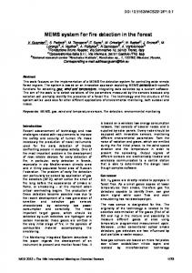
Fig. 3. Fabrication process sequence. (a) Making recess on a glass. (b) Bond glass substrate to a silicon wafer. (c) Thin the silicon wafer down to desired thickness. (d) Deposit metal contact. (e) DRIE to release the structure.
SoG MEMS accelerometer.
position coordinates on the screen. In the next section, each subcomponent is explained in details. D. MEMS Accelerometer Typically, there are three different types of MEMS accelerometers: piezoresistive [8], tunneling [9], and capacitive [10], [11]. The capacitive accelerometer was chosen for this system because it provides high sensitivity, good dc response, low drift, low temperature sensitivity, low-power dissipation, and a simple structure [12]. For implementation, SoG technology is used to take advantage of its robustness and simplicity of design. Fig. 2 shows the structure of an SoG lateral accelerometer [10]. A MEMS accelerometer consists of two major components: a proofmass and sensing electrodes. A thick silicon proofmass is connected to a frame, which is anchored to a glass substrate with suspension beams and comb fingers are formed using deep reactive ion etching (DRIE). Since the proofmass is suspended over recess on a glass substrate with serpentine suspension beams, it is free to move with a response to external acceleration. On the other hand, electrodes are attached to the glass substrate. When external forces are applied to the accelerometer—for example, by the user’s hand movement—the proofmass moves against the forced direction due to an inertia force while the electrodes are stationary. The movement causes capacitance variations between the comb fingers which form parallel-plate . One side of the comb fingers genercapacitors, denoted as ates a positive variation , and the other side produces . The total capacitance change is the a negative one . difference between these two values Therefore, the external acceleration is converted to the differential capacitance variation which can be expressed as pF/g
(1)
where is the mass of a proofmass, is the rest capaciis the sensing gap distance, and is the spring contance, stant of suspension beams [11]. From (1), it can be expected that a heavy accelerometer with a large number of comb fingers and compliant structure—i.e., small spring constant—provides good sensitivity, although it is difficult to fabricate such accelerometers. The dimension of the fabricated single-crystal ) silicon proofmass is 2.1 mm 2.4 mm 100 m (
Fig. 4. Top view of a fabricated MEMS accelerometer.
and weighs 0.25 mg. The sense capacity and sensitivity are approximately 16.4 pF and 0.78 pF/g, and the noise floor is 10 g/Hz. For the 2-D mouse system, two lateral accelerometers are required for sensing - and -axis accelerations. A schematic top view of the MEMS accelerometer in Fig. 2 is shown in Fig. 5(a). The fabrication process has five steps requiring only three masks. Fig. 3 shows the cross section of the wafer for each fabrication step. In the first step, a recess is formed on the glass substrate [Fig. 3(a)]. Then, the glass wafer with recess is anodically bonded to silicon water [Fig. 3(b)]. Next, the silicon wafer is thinned to desired thickness with chemical mechanical polishing (CMP) [Fig. 3(c)]. Metal contacts are evaporated [Fig. 3(d)], and, finally, a deep DRIE etch is performed to release the structure [Fig. 3(e)]. Fig. 4 shows a scanning electron microscope (SEM) picture of a MEMS accelerometer taken after fabrication. MEMS accelerometers can be readily integrated to other circuits using post-CMOS processing [13]–[15]. E. CMOS Analog Readout Circuits The detected acceleration, which is represented as a differential capacitive variation from the MEMS accelerometer as illustrated in Fig. 5(a), is modulated to pulsewidth by the analog readout circuitry as shown in Fig. 5. In general, the lateral accelerometer presented in Section II-D can be operated either in open-loop mode or closed-loop mode. In closed-loop operational mode, the overall performance such as linearity, dynamic range, and bandwidth are improved [11]. In our design, an electromechanical oversampled modulator is used because it provides direct digital output and force feedback control of the proofmass simultaneously over a wide dynamic range.
Authorized licensed use limited to: Arizona State University. Downloaded on March 6, 2009 at 14:49 from IEEE Xplore. Restrictions apply.
1170
IEEE TRANSACTIONS ON VERY LARGE SCALE INTEGRATION (VLSI) SYSTEMS, VOL. 13, NO. 10, OCTOBER 2005
Fig. 5. Sigma–delta electromechanical modulator with clock phases. (a) Illustration of capacitive accelerometer model for electronic interface. (b) Sigma–delta electromechanical modulator circuit schematics. (c) Clock phases.
Another various class of electromechanical modulators, the switched-capacitor sigma–delta electromechanical modulator [Fig. 5(b)], is employed because it is insensitive to the input parasitic capacitance. An efficient gain- and offset-compen. sated integrator is obtained by using an offset-storage This technique is called the correlated double sampling (CDS) noise and offset in op-amp. technique [16] and can reduce The circuit uses a single-ended charge integrator to read out the capacitance variation, and the static comparator forms the loop quantizer. Finally, a digital flip-flop samples the output from the comparator and synchronizes its bitstream with the system clock. Since the proofmass can be modeled as a second-order system, the closed-loop system becomes unstable, so a simple is inserted in the feedback path for lead compensator stability. There are four clock phases in the switched-capacitor inter, the sense caface circuit [Fig. 5(c)]. During the first phase pacitors formed between electrodes and proofmass are reset and the op-amp offset voltage is stored on . In the second phase
, sense capacitors and are charged through and . The charge difference between and is integrated on the feedback capacitor , while the comparator quantizes the charge. In this phase, the offset voltage stored in is subtracted and thus the output voltage op-amp is compensated. The amplitude of op-amp output voltage corresponds to the magnitude of applied acceleration. For example, if the MEMS device gets positive acceleration, then the proofmass is closer to the left anchor of the MEMS accelerometer and is bigger than . Since is connected to the negative , the negative net charge is sampled to an reference voltage integrator, generating positive op-amp output voltage. The capacitance sensitivity defined as the op-amp output voltage due is calculated by to input capacitance charge (2) From (2), the capacitance sensitivity is approximately 0.33 V/pF. The quantized output is also latched at the end of
Authorized licensed use limited to: Arizona State University. Downloaded on March 6, 2009 at 14:49 from IEEE Xplore. Restrictions apply.
LEE et al.: 2-D POSITION DETECTION SYSTEM FOR PADLESS MOUSE APPLICATIONS
Fig. 6.
HSPICE simulation for analog readout circuit.
Fig. 8. Fig. 7. 4.5 mm
1171
Brownian noise.
Layout for sigma–delta analog readout circuitry (die size:
2 2.6 mm).
this phase. In the third phase , the output of the flip-flop is fed back to the MEMS accelerometer to place the proofmass in the null position by electrostatic forces. If the proofmass gets positive (negative) accelerations, the output of comparator will be positive (negative) because of its voltage inversion. This supply voltage is reapplied to the proofmass to make it return to the null position by electrostatic forces. The last phase is used for the control and sensing of the proofmass. The output of the flip-flop forms pulse bitstreams for the next module. Fig. 6 shows the HSPICE simulation result of the modulation of acceleration magnitudes into the corresponding digital pulse bitstreams (PWM signal). As the acceleration changes, capacitance differences between proofmass and electrodes are sensed and the corresponding charge is integrated with a 90 phase lag. The integrated charges are reflected to the voltage at the output and passed through the comparator generating a PWM signal. The layout for analog readout circuit shown in Fig. 7 is composed of all the components necessary such as switches, amplifier, comparator, D-flip-flop, and clock generator. F. Noise Analysis of Closed-Loop System There are several noise sources that affect the resolution (i.e., the minimum detectable input acceleration) of the overall system. In an oversampled electromechanical sigma–delta system, higher sampling rates reduce the quantization noise. Each doubling of the sample frequency results in a 3-dB
Fig. 9. Electronic noises. (a) Amplifier thermal noise. (b) KT =C noise due to thermal noise sampling switches.
signal-to-noise ratio (SNR) improvement. Based on the sensitivity of accelerometer and capacitance, the equivalent input noise of acceleration can be calculated. Each noise source now will be described. 1) Brownian Noise: The primary mechanical noise source for the device is due to the Brownian motion (Fig. 8) of gas
Authorized licensed use limited to: Arizona State University. Downloaded on March 6, 2009 at 14:49 from IEEE Xplore. Restrictions apply.
1172
Fig. 10.
IEEE TRANSACTIONS ON VERY LARGE SCALE INTEGRATION (VLSI) SYSTEMS, VOL. 13, NO. 10, OCTOBER 2005
Mass residual motion noise.
molecules between comb fingers. The total noise equivalent ac)] [12] is celeration (TNEA) [m/(s (3) is the Boltzmann constant, is the temperature where is damping coefficient, and is resonance frein Kelvin, quency. From (3), it is seen that the MEMS accelerometer has smaller Brownian noise with larger and heavier proofmass. Plugging device data into this equation results in Brownian . motion noise around 10 g/ 2) Amplifier Noise: The readout circuitry utilizes correlated doubling sampling to reduce the input CMOS amplifier flicker noise. However, the amplifier thermal noise [Fig. 9(a)] is amplified by the ratio of total input capacitors, including parasitics in the integrating capacitor. The noise at the output of the amplifier can be expressed by integrating the total noise power and dividing it by the effective noise bandwidth, which is half of the sampling frequency. Therefore, the amplifier output noise voltage due to thermal noise in the op-amp is expressed as (4) where is the total input capacitance including parasitics, is the capacitance of the op-amp output node, and is the sampling frequency. From this equation, the equivalent input acceleration noise due to amplifier thermal noise is about 0.7 g/ Hz. 3) KT/C Noise: A major noise source in switched capacnoise [Fig. 9(b)], which is generated by itor circuits is the CMOS switch thermal noise. The rms voltage noise from thermal switch noise can be calculated by the integration of the bandwidth of switch’s RC filter. The voltage noise power density due to this switch thermal noise is expressed as -
(5)
This voltage noise is converted to the equivalent input acceleration noise as 0.3 g/ Hz. 4) Mass Residual Motion Noise: The proofmass is being rebalanced by a pulse train, and thus it has a residual motion with small ac amplitude (Fig. 10). The amplitude of this motion can be shown [17] to be approximately equal to m with g and 100 kHz. This residual motion corresponds to an equivalent rms of 78 mg acceleration in this MEMS accelerometer.
This acceleration can be randomized due to the varying input, and hence it can be considered to be noise distributed uniformly . This from dc to the proofmass residual motion frequency and becomes dominant due noise is equivalent to 500 g/ to its low sampling frequency. 5) Dead-Zone Noise: Assuming that the input of the accelerometer is zero, the feedback voltage generates with frequency because of electrostatic force. Therefore, the input signal must be large enough to break this dead-zone pattern. The minimum rms input acceleration for g and should be this is counted as noise. 6) Total Noise and Minimum Detectable Acceleration: Since all of the noise sources considered here are uncorrelated, the total noise is obtained simply by summing all of the noise . Therefore, the minimum sources, resulting in 530 g/ detectable acceleration is the same as the one calculated by integrating this input acceleration density over the bandwidth of interest, which is 100 Hz. The resultant minimum detectable acceleration is about 5.3 mg, which is below the smallest acceleration a human hand can generate/perceive. From the noise-source consideration, we see that the mass residual noise dominates with order of magnitude. However, this mass residual motion noise can be significantly reduced by increasing the sampling frequency at the cost of power consumption and complexity. G. Acceleration Magnitude Extractor The modulated pulse bitstream from the CMOS analog readout circuit is converted into binary data for further processing. Two types of data should be extracted from pulse bitstreams: polarity and magnitude. The polarity indicates the direction of acceleration and can be handily extracted by observing the sign of pulse bitstreams. For example, Fig. 11 illustrates the movements of the mouse and corresponding acceleration values on both the and axes. It also shows the possible PWM bit streams. If the value of the pulse is 5 V (digital value “1”), the acceleration is toward the positive direction, and vice versa. The width of pulse bitstreams is proportional to the magnitude of acceleration. The extraction of correct magnitude of acceleration can be achieved via two binary flags (flip-flops) and a binary counter, as shown in Fig. 12. The “C” flag is set to the polarity of current input pulse bitstream synchronized by the system clock while the “P” flag value is the one shifted from the “C” flag flip-flop from the previous clock cycle. The comparator compares the two flag values and, when-
Authorized licensed use limited to: Arizona State University. Downloaded on March 6, 2009 at 14:49 from IEEE Xplore. Restrictions apply.
LEE et al.: 2-D POSITION DETECTION SYSTEM FOR PADLESS MOUSE APPLICATIONS
Fig. 11.
Movements of a mouse and corresponding accelerations in
1173
X and Y axes. generated values is proportional to the degree of the acceleration of movements, and the polarity of the input bitstreams determines the direction of user’s movements. In other words, the positive value of the counter corresponds to the positive acceleration, and vice versa. The “acceleration register” always keeps some static values specifying the previous acceleration magnitude, and the control microprocessor accesses only this register to calculate the current position cursor. Whenever the acceleration register loads a new value from the counter, the “N” flag flip-flop is set to “1,” indicating that the new value has been loaded. The control microprocessor keeps polling “N” flag flip-flops to decide whether it should fetch a new acceleration value or not. The layout for acceleration magnitude extractor is assembled together with core microprocessor and is shown in Fig. 16. H. Core Control Microprocessor
(b) Fig. 12. Acceleration magnitude extractor. (a) Overall structure. (b) Operation illustration.
ever two flag values differ—e.g., the polarity of input stream changes—it loads the current value of binary counter into the buffer register called “acceleration register” and, at the same time, it resets the counter. While “C” and “P” flag flip-flops have the same value, the counter keeps increasing or decreasing based on the value of the “C” flag. Thus, the magnitude of
The core control microprocessor is designed to filter the acceleration output from the analog readout circuits within the bandwidth of interest and to remove the quantization noise folded at higher frequency. This can be done with a simple finite impulse response (FIR) low-pass filter with 100-Hz cutoff frequency. Also, the microprocessor calculates the position coordinates based upon the magnitude values of the acceleration from the acceleration extract module. The processor is based on RISC concepts and is implemented as a modified two-stage (fetch/decode and execute) pipeline (see Fig. 13). Instruction fetch takes place during the half cycle before the instruction is decoded to allow a full half-cycle for instruction memory access and a full cycle for decoding the instruction. The microprocessor uses a 16-b word and address space and all instructions are single-word. In addition to the basic arithmetic and logic operations, two application-specific instructions are implemented, which will be described below. The main part of the application program consists of two procedures: polling and integration. For the polling procedure, a special instruction is defined called load counter value (LCNT).
Authorized licensed use limited to: Arizona State University. Downloaded on March 6, 2009 at 14:49 from IEEE Xplore. Restrictions apply.
1174
IEEE TRANSACTIONS ON VERY LARGE SCALE INTEGRATION (VLSI) SYSTEMS, VOL. 13, NO. 10, OCTOBER 2005
Fig. 13.
Core microprocessor architecture.
Fig. 14.
Timing strategy.
When LCNT is executed, the core control microprocessor examines the value of the “N” flag flip-flip from the previous acceleration extract module. If the value of the flip-flop is “1,” the value of the acceleration register is transferred into one of registers in the data-path module. At the same time, the “N” flag flip-flop is reset to “0” by the microprocessor to indicate the completion of the transferring operation. The transferred acceleration magnitude value should be integrated twice so that it is transformed into position coordinates as shown in the following equation: (6) and represent velocity, acceleration, and position where coordinates, respectively. Instead of implementing the integration operation, it is performed via two normal addition instrucand . Since the system has abundant tions: instruction cycles for each coordinate calculation, as pointed out in Section II-A, the lack of special-purpose hardware is justified.
The other special instruction is called SROUT, which moves calculated coordinate values to the 16-b system interface bus. To minimize the interface with outside circuitry, instruction memory (ROM) and data memory (RAM) have been integrated into the core microprocessor module. Both ROM and RAM contain 256 words, which is large enough to contain the entire application program. I. Timing Scheme and Critical Paths The general timing strategy of the core microprocessor is shown in Fig. 14. The clocking is predominantly positive edgetriggered, except for the program counter. The program counter is a negative edge-triggered component to allow enough instruction memory access time between and . At time , an instruction is loaded into the instruction register, and, between and , the newly fetched instruction is decoded. In our design, every control signal is latched (as shown at time ) to provide stabilized control signals for safe execution of the instruction
Authorized licensed use limited to: Arizona State University. Downloaded on March 6, 2009 at 14:49 from IEEE Xplore. Restrictions apply.
LEE et al.: 2-D POSITION DETECTION SYSTEM FOR PADLESS MOUSE APPLICATIONS
1175
Fig. 15. Timing delay for the critical path.
Fig. 16.
Microprocessor layout (5.6 mm
2 5.8 mm).
during the next clock cycle from to . In other words, the entire clock period is dedicated to execute one instruction. Finally, at time , the result of the execution is written back to either the register file or the data memory. The rationale behind this timing strategy is to distribute major timing loads to different clock cycles evenly, resulting in the reduced clock period. Our microprocessor design does not have separate memory address register (MAR) or memory data register (MDR), because both instruction memory (ROM) and data memory (RAM) are integrated together with the processor. Thus, memory access instructions (Load/Store) are virtually the same with a register transfer instructions (Mov/Movi), which simplifies the system architecture. Through extensive simulation, the paths from the register file to ALU were determined to be critical primarily because the register file is the largest component and the ALU has a ripple-carry adder (see Fig. 15). The ALU delay time is 53.7 ns, which is measured from the rising clock edge to the point when the calculated data are valid on the system data bus. This critical path permits a maximum clock frequency of approximately 18 MHz, which is above the target frequency of 100 kHz. Recalling that the application target frequency dictates the maximum critical delay, the ripple-carry adder showed adequate performance in this regard, and a faster ALU was not necessary. III. VERIFICATION AND TESTING Verification and simulation were performed using the Mentor Graphics Tools and Epoch Design Compiler. Mentor’s
Fig. 17. Process flow of monolithic implementation. (a) SOI wafer. (b) Analog/digital CMOS process. (c) Deep trench etching. (d) Release.
Quicksim Pro was used for transistor-level and Verilog simulation. Parasitics were extracted from the layout, and Mentor’s Accusim was used for the detailed delay and loading effects. Timing information from the parts generated in Epoch [23] was extracted automatically during the import process to Mentor’s Design Architect. Once the functional models were properly back annotated, timing verification was performed in Quicksim Pro. In order to physically verify the design, full-mask LVS was performed by importing the custom datapath into Epoch and generating a net-list for the entire core that includes the custom and Epoch-synthesized parts. To facilitate testing, the program counter and instruction register were made scannable. The application-specific instruction SROUT moves the specified register value to 16-b output pins (SOUT[15:0]), allowing us to observe any arbitrary register values of the register file during the testing mode. These two design-for-testability features allow us to verify the contents of instruction/data memory efficiently. By applying instruction addresses at the program counter and observing the values of instruction register via scan-chain testing mode, the correctness of the instruction memory (ROM) were verified. Data memory (RAM) was verified by moving contents of a specific memory
Authorized licensed use limited to: Arizona State University. Downloaded on March 6, 2009 at 14:49 from IEEE Xplore. Restrictions apply.
1176
Fig. 18.
IEEE TRANSACTIONS ON VERY LARGE SCALE INTEGRATION (VLSI) SYSTEMS, VOL. 13, NO. 10, OCTOBER 2005
MEMS accelerometer for monolithic implementation.
location into one of the register in the register file and transferring them to the system interface bus via SROUT instruction. IV. DESIGN STATISTICS MEMS accelerometer was designed to have characteristics such as sensitivity with 0.78 pF/g, dimensions as ), and a sensing 2.1 mm 2.4 mm 100 m ( capacitance of 16.4 pF. The analog circuit has an estimated power of 3 mW, capacitance sensitivity of 0.3 V/pF, and die size of 4.5 mm 2.6 mm. Mechanical and analog simulation shows that the designed padless mouse system can detect acceleration as small as 5.3 mg, which is a sufficiently high resolution for mouse applications. The microprocessor, as shown in Fig. 16, contains 53 634 transistors, and the die size is 5.6 mm 5.8 mm. As described in Section II-I, the critical path was from the register file to ALU, and the corresponding maximum clock frequency was approximately 18 MHz. Although maximum achievable clock speed is 18.1 MHz, its operational frequency is same as the sampling frequency of the analog switched-capacitor sigma-delta readout circuits. The power consumption is estimated to be 10 W at 100-kHz operational frequency. V. MONOLITHIC IMPLEMENTATION The hybrid 2-D position detection system has been proposed to combine MEMS accelerometers and digital circuits by means of switched-capacitor circuits using wire bonding. Due to the wire being bonded, however, these different modules in a system must interface with each other at board level. This not only limits the size of a system, but also contributes capacitive or resistive parasitics that may degrade the system performance [24]. For example, stray capacitance and inductance due to wire bonding and bond pads can be up to 1 pF/pad and 1 nH/mm, respectively. To circumvent these drawbacks, a system-on-chip (SoC)
design and fabrication, where all of the modules are fabricated in a single wafer, are considered as a monolithic implementation. In other words, all of the necessary modules such as MEMS accelerometers, the analog readout circuit, and the microprocessor are to be integrated on the same wafer without any interfaces between them. The only major interface with outside circuits—other than VDD, GND, clock, and reset signals—is the parallel data bus which transfers positional coordinates calculated from the microprocessor. Since they are fabricated on the same wafer, thus eliminating complex steps for the interface, it greatly reduces the overall costs as well as complex steps for the interface. With all of these advantages over the hybrid system, however, the monolithic system has several problems such as noise between analog and digital circuits, interconnections between MEMS devices and analog circuits, and so on. One of the main factors for a noise problem in monolithic system stems from the fact that the analog and digital circuits are sharing the same substrate. Although substrate has high resistance, it is not a complete isolator, and thus voltage variations in digital parts are capacitively coupled to analog circuits and thus may cause malfunctions of a system. The noise problem due to the substrate coupling can be solved by using silicon-on-insulator (SOI) [18]–[22], which isolates one module from others by etching substrate boundaries of each module and making it isolated both physically and electrically. Also, MEMS accelerometers and analog circuitry can be connected to each other by making deep trenches. It is reported that the silicon substrate underneath interconnection materials (such as metals) can be removed in the process of deep trench etching because of a sidewall etching effect [14]. The detailed fabrication process flow for monolithic implementation combining MEMS devices and analog and digital circuits are basically post-CMOS fabrication, as illustrated in Fig. 17. The usual CMOS processes are done using SOI start wafers, as shown in Fig. 17(a) and (b). After CMOS processes, deep trenches are
Authorized licensed use limited to: Arizona State University. Downloaded on March 6, 2009 at 14:49 from IEEE Xplore. Restrictions apply.
LEE et al.: 2-D POSITION DETECTION SYSTEM FOR PADLESS MOUSE APPLICATIONS
made for the formation of proofmass of MEMS accelerometers as well as isolation between analog and digital circuitry [Fig. 17(c)]. Fig. 17(d) presents the release step by removing SiO with buffered hydrofluoric acid to suspend the proofmass. During the release, the SiO between analog/digital circuitry are also etched away. Finally, Fig. 18 shows the mask-level MEMS structure. The close-up view shows an interconnection line, contacts, suspension beams, and etch holes which help releasing proofmass during BHF etch process.
VI. CONCLUSION In this paper, we presented a novel 2-D position detection system for padless mouse applications. The final system consists of four major components: 1) MEMS accelerometer; 2) analog readout circuit; 3) acceleration magnitude extraction module; and 4) 16-b RISC microprocessor. Each module was carefully designed, laid out, and verified through extensive simulation. The calculated and simulated minimum detectable acceleration is 5.3 mg with a 100-kHz low sampling frequency for low power consumption. The hybrid multichip nature of the proposed system will limit the system size and contribute capacitive and resistive parasitics that may degrade the system performance. To circumvent these drawbacks, an SoC design and fabrication, where all of the modules are fabricated on a single wafer, is considered as future work in this area. Also, the system can be handily extended into a 3-D position detection system by adding an additional MEMS accelerometer to measure -axis directional movement.
REFERENCES [1] R. C. Harwell and R. L. Ferguson, “Physiologic tremor and microsurgery,” Microsurg., vol. 4, pp. 187–192, 1983. [2] C. N. Riviere and P. K. Khosla, “Accuracy in positioning of handheld instruments,” in Proc. 18th Annu. Conf. IEEE Engineering in Medicine and Biology Society, 1996, pp. 212–213. [3] C. N. Riviere, R. S. Rader, and P. K. Khosla, “Characteristics of hand motion of eye surgeons,” in Proc. 19th Annu. Conf. IEEE Engineering in Medicine and Biology Society, 1997, pp. 1690–1693. [4] K. A. Mann, F. W. Werner, and A. K. Palmer, “Frequency spectrum analysis of wrist motion for activities of daily living,” J. Orthop. Res., vol. 7, pp. 304–306, 1989. [5] J. M. Hollerbach, “An oscillatory theory of handwriting,” Biol. Cybern., vol. 39, pp. 139–156, 1981. [6] R. N. Stiles and J. E. Randall, “Mechanical factors in human tremor frequency,” J. Appl. Physiol., vol. 23, no. 3, pp. 324–330, 1967. [7] J. E. Randall and R. N. Stiles, “Power spectral analysis of finger acceleration tremor,” J. Appl. Physiol., vol. 19, pp. 357–360, 1964. [8] L. M. Roylance and J. A. Angell, “A batch-fabricated silicon accelerometer,” IEEE Trans. Electron Devices, vol. ED-26, no. 12, pp. 1911–1917, Dec. 1979. [9] C. Yeh and K. Najafi, “A low-voltage bulk-silicon tunneling based microaccelerometer,” IEDM Tech. Dig., pp. 593–596, Dec. 1995. [10] J. S. Chae, H. Kulah, and K. Najafi, “An in-plane high-sensitivity, lownoise micro-g silicon accelerometer with CMOS readout circuitry,” J. Microelectromechanical Syst., vol. 13, no. 4, pp. 628–635, Aug. 2004. [11] N. Yazdi and K. Najafi, “An all-silicon single-wafer fabrication technology for precision micro accelerometers,” in Proc. 9th Int. Conf. SolidState Sensors and Actuators, 1997, pp. 1181–1184. [12] N. Yazdi, F. Ayazi, and K. Najafi, “Micromachined inertial sensors,” Proc. IEEE, vol. 86, no. 8, pp. 1640–1659, Aug. 1998.
1177
[13] Z. Xiao et al., “Laterally capacity sensed accelerometer fabricated with the anodic bonding and the high aspect ratio etching,” in Proc. 10th Int. Conf. Solid-State Sensors and Actuators, 1999, pp. 1518–1521. [14] H. Xie et al., “Post-CMOS processing for high-aspect-ratio integrated silicon microstructures,” in Proc. IEEE Solid-State Sensor and Actuator Workshop, 2000, pp. 77–80. [15] J. Chae, H. Kulah, and K. Najafi, “A hybrid silicon-on-glass (SOG) lateral micro-accelerometer with CMOS readout circuitry,” in Proc. 15th IEEE Int. Conf. Micro Electro Mechanical Systems, 2002, pp. 623–626. [16] C. C. Enz and G. C. Temes, “Circuit techniques for reducing the effects of op-amp imperfections: Autozeroing, correlated double sampling, and chopper stabilization,” Proc. IEEE, vol. 84, no. 11, pp. 1584–1614, Nov. 1996. [17] B. Boser and R. T. Howe, “Surface micromachined accelerometers,” IEEE J. Solid-State Circuits, vol. 31, no. 3, pp. 366–375, Mar. 1996. [18] Y.-C. Tseng, “AC floating body effects and the resultant analog circuit issues in submicron floating body and body-grounded SOI MOSFETs,” IEEE Electron Devices, vol. 46, no. 8, pp. 1685–1692, Aug. 1999. [19] S. Krishnan and J. G. Fossum, “Grasping SOI floating-body effects,” IEEE Circuits Devices Mag., vol. 14, no. 1, pp. 32–37, Jan. 1998. [20] G. G. Shahidi et al., “Partially-depleted SOI technology for digital logic,” in Proc. ISSCC, 1999, pp. 426–427. [21] C.-T. Chuang, P.-F. Lu, and C. J. Anderson, “SOI for digital CMOS VLSI: Design considerations and advances,” Proc. IEEE, vol. 86, no. 4, pp. 689–720, Apr. 1998. [22] K. K. Das and R. B. Brown, “Evaluation of circuit approaches in partially-depleted SOI-CMOS,” in Proc. SOI Conf., 2000, pp. 98–99. [23] Epoch: Online Manuals, Cascade Design Automation Corporation, 1994. Epoch, Online. [24] N. H. E. Weste and K. Eshraghian, Principles of CMOS VLSI Design: A System Perspective, 2nd ed. Reading, MA: Addison-Wesley, 1993.
Seungbae Lee (S’01) received the B.S and M.S. degrees from Seoul National University, Seoul, Korea, in 1990 and 1992, respectively. He is currently working toward the Ph.D. degree in electrical engineering and computer science at the University of Michigan, Ann Arbor. From 1992 to 1997, he was a Senior Research Engineer with LG Electronics Institute of Technology, Seoul, where he was involved with the research and development of speech recognition and synthesis. His current research interests focus on microelectromechanical systems for RF wireless communications and include micromechanical resonator reference oscillator and integrated circuit design. Mr. Lee was the recipient of the First Prize and Best Paper Awards in the Student Design Contest at the 38th Design Automation Conference and the Best Paper Award at the 2004 IEEE Frequency Control Symposium.
Gi-Joon Nam (S’99–M’01) received the B.S. degree in computer engineering from Seoul National University, Seoul, Korea, and the M.S. and Ph.D. degrees in computer science and engineering from the University of Michigan, Ann Arbor. Since 2001, he has been with IBM Austin Research, Austin, TX, and is currently working on physical design space, particularly placement and timing closure flow. His general interests are computer-aided design algorithms, combinatorial optimizations, VLSI system designs, and computer architecture. Dr. Nam is a member of the Association for Computing Machinery. He is currently serving on the Technical Program Committee for the ACM/IEEE International Symposium on Physical Design (ISPD) and IEEE International System-on-Chip Conference (SOCC). He is currently serving on the Technical Program Committee for the International Conference on Computer Design.
Authorized licensed use limited to: Arizona State University. Downloaded on March 6, 2009 at 14:49 from IEEE Xplore. Restrictions apply.
1178
IEEE TRANSACTIONS ON VERY LARGE SCALE INTEGRATION (VLSI) SYSTEMS, VOL. 13, NO. 10, OCTOBER 2005
Junseok Chae (M’03) received the B.S. degree in metallurgical engineering from Korea University, Seoul, Korea, in 1998 and the M.S. and Ph.D. degrees in electrical engineering and computer science from the University of Michigan, Ann Arbor, in 2000 and 2003, respectively. From 2003, to 2005, he was a Postdoctoral Research Fellow with Wireless Integrated MicroSystems (WIMS), University of Michigan. He joined the faculty of Arizona State University, Tempe, in August 2005, where he is currently an Assistant Professor of electrical engineering. His areas of interests are MEMS sensors, mixed-signal interface electronics, MEMS packaging, and ultrafast pulse (femtosecond) lasers for micro-/nano-structures. He holds several U.S. patents. Dr. Chae, along with his colleagues, was the recipient of the First Place Prize and the Best Paper Award at the Design Automation Conference Student Design Contest in 2001 with the paper titled “Two-dimensional position detection system with MEMS accelerometer for mouse application.” He gave an invited talk at Microsoft Inc. regarding “MEMS technology for consumer electronic applications.”
Hanseup Kim (S’00) received the B.S. degree from Seoul National University, Seoul, Korea, in 1997 and the M.S. degree from the University of Michigan, Ann Arbor, in 2003, both in electrical engineering. He is currently working toward the Ph.D. degree in electrical engineering in microelectromechanical systems (MEMS) at the University of Michigan. He interned at LG Corporate Institute of Technology, Korea, in early 1999, where he participated in developing a microoptical switch. Since entering the graduate program in 1999, he has been developing a micro vacuum pump for use in a miniaturized gas chromatograph as well as several polymer-based microfabrication technologies such as wafer bonding and membrane transfer techniques. Recently, he has also been involved with the development of bidirectional micro loud-speaker and chip-cooling chip using acoustic thrust generation. His research interests include the design and microfabrication of micro actuators and MEMS systems as well as their integrations with circuits. Up to date, he has authored and coauthored 15 papers in refereed journals and conferences and has served as a technical reviewer for the Journal of Microelectromechanical Systems. Mr. Kim was the recipient of the Best Paper and First Place Awards at the 38th Student Design Contest of Design Automation Conference (DAC 2001) with four other coauthors.
Alan J. Drake (S’99) received the B.S. degree in electrical engineering from the University of Arizona, Tucson, in 1997 and the M.S. degree in electrical engineering from the University of Michigan, Ann Arbor, in 2000, where he is currently working toward the Ph.D. degree. Currently, he is with IBM Austin Research, Austin, TX. His research interests include low-power VLSI, resonant clock generation and distribution, and SOI technology.
Authorized licensed use limited to: Arizona State University. Downloaded on March 6, 2009 at 14:49 from IEEE Xplore. Restrictions apply.