Hindawi Publishing Corporation Journal of Nanoscience Volume 2013, Article ID 217382, 9 pages http://dx.doi.org/10.1155/2013/217382
Research Article Two-Dimensional Variable Property Conjugate Heat Transfer Simulation of Nanofluids in Microchannels A. Ramiar and A. A. Ranjbar Faculty of Mechanical Engineering, Babol Noshirvani University of Technology, Shariati Avenue, P.O. Box 484, Babol, Mazandaran 47148 71167, Iran Correspondence should be addressed to A. Ramiar;
[email protected] Received 30 March 2013; Accepted 12 October 2013 Academic Editor: Zhengjun Zhang Copyright © 2013 A. Ramiar and A. A. Ranjbar. This is an open access article distributed under the Creative Commons Attribution License, which permits unrestricted use, distribution, and reproduction in any medium, provided the original work is properly cited. Laminar two-dimensional forced convective heat transfer of CuO-water and Al2 O3 -water nanofluids in a horizontal microchannel has been studied numerically, considering axial conduction effects in both solid and liquid regions and variable thermal conductivity and dynamic viscosity. The results show that using nanoparticles with higher thermal conductivities will intensify enhancement of heat transfer characteristics and slightly increases shear stress on the wall. The obtained results show more steep changes in Nusselt number for lower diameters and also higher values of Nusselt number by decreasing the diameter of nanoparticles. Also, by utilizing conduction number as the criterion, it was concluded from the results that adding nanoparticles will intensify the axial conduction effect in the geometry considered.
1. Introduction In the last two decades, many cooling technologies have been pursued to meet the high heat dissipation rate requirements and maintain a low junction temperature for electronic components. Among these efforts, the microchannel heat sink (MCHS) has received much attention because of its ability to produce high heat transfer coefficient, small size and volume per heat load, and small coolant requirements [1]. Tuckerman and Pease [2] were first to introduce the concept of microchannel heat sinks for high heat flux removal and employ water flowing under laminar conditions in silicon microchannels. Afterwards, various aspects of the fluid flow in microchannel have been studied experimentally and numerically. Some of them, such as Li et al. [3], Hetsroni et al. [4], and Lee and Garimella [5], have done experimental observations to analyze microchannels from friction and heat transfer point of view and others such as Gamrat et al. [6] and Xie et al. [7] studied numerical aspects of them. Also some others used different numerical methods to consider the conjugate heat transfer characteristics such as Wang et al. [8] who used Lattice Boltzmann method. Nanofluids have been proposed as a means to enhance the performance of heat transfer liquids currently available.
Recent experiments on nanofluids have indicated significant increase in thermal conductivity compared with liquids without nanoparticles or larger particles, strong temperature dependence of thermal conductivity, and significant increases in critical heat flux in boiling heat transfer. Fluid flow and heat transfer of nanofluid in different geometries have been studied by several authors such as Santra et al. [9], but there are little works related to the nanofluid flow in microchannel. Koo and Kleinstreuer [10] studied the effect of nanoparticles concentrations on different parameters of microchannel heat sinks. They considered two combinations of copperoxide nanoparticles in water or ethylene glycol and used their own models for the effective thermal conductivity and dynamic viscosity for nanofluids. Their results proved the ability of nanofluids to enhance the performance of heat sinks. Jang and Choi [11] used their thermal conductivity model [12] to predict thermal performance of microchannel heat sinks using nanofluids. Their results showed an enhancement of 10% for water-based nanofluids containing diamond (1 vol.%, 2 [nm]) at the fixed pumping power. Tsai and Chein [13] addressed analytically the effect of adding copper nanoparticle and carbon nanotube to water in performance of microchannel heat sink. It was found that using nanofluid can only enhance the microchannel heat sink performance when
2
Journal of Nanoscience
y
H
and the top wall of this region is adiabatic. For the solid region, a uniform heat flux is exerted from below and side walls are considered adiabatic:
Fluid region
x
Hs
Solid region
−𝑘𝑠
L q
𝜕𝑇𝑠 = 0, 𝜕𝑥
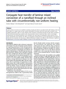
Figure 1: Schematic illustration of the 2D microchannel.
the porosity and aspect ratio are less than the optimum porosity. Bhattacharya et al. [14] analyzed numerically laminar conjugate heat transfer characteristics of Al2 O3 -water nanofluid flowing in a silicon microchannel heat sink. They found that the improvement of microchannel heat sink performance due to use of nanofluid becomes more pronounced with increase in nanoparticle concentration. They also showed that fully developed heat transfer coefficient for nanofluid flow in microchannel heat sink increases with Reynolds number even in laminar flow regime rather than a constant. Ho et al. [15] investigated enhancement of forced convective heat transfer in a copper microchannel heat sink with Al2 O3 -water nanofluid of 1 and 2 vol.% as the coolant and the Reynolds number ranging from 226 to 1676. It was demonstrated that adding nanofluids significantly increases the average heat transfer coefficient. In this paper, the effect of concentration of 18 [nm] CuO nanoparticles in water will be studied from hydrodynamic and heat transfer point of view. Then, the effect of nanoparticles type and diameter in the performance of the microchannel will be considered. And finally, the effect of nanofluid on conjugate heat transfer will be discussed by means of Conduction number.
The problem under consideration consists of steady, forced laminar convection flow and heat transfer of a nanofluid flowing inside a straight 2D microchannel. The geometry and boundary conditions of the 2D microchannel are shown in Figure 1. The channel height is H = 90 [𝜇m] and its length is L = 7 [cm]. CuO-water nanofluid enters the channel in a constant temperature of 303 [K] and constant velocity. The flow condition is laminar, and a wide range of Reynolds number from 10 to 1200 has been considered. The solid region is made of silicon (ks = 120 [Wm−1 K−1 ]) with different heights from b = H s /H = 2 to 100. Boundary conditions for the fluid region are as follows. No slip condition for all solid surfaces, or 𝑢 = V = 0 at 𝑥 = 0, 𝑦 = 0, and 𝑦 = 𝐻, uniform velocity and temperature distribution profile at the inlet: 𝑇 = 𝑇in ,
0 ≤ 𝑦 ≤ 𝐻,
(1)
and zero normal stress and fully developed temperature field at the outlet: 𝜕𝑢 = 0, 𝜕𝑥
2
𝜕𝑇 = 0, 𝜕𝑥2
0 ≤ 𝑦 ≤ 𝐻,
(2)
𝑦 = −𝐻𝑠 , (3)
𝑥 = 0, 𝑥 = 𝐿.
Finally the conjugate heat transfer boundary condition for the interface between the two regions is 𝑘𝑠 (
𝜕𝑇𝑓 𝜕𝑇𝑠 = 𝑘nf ( ) ) 𝜕𝑦 solid 𝜕𝑦 nanofluid
𝑦 = 0.
(4)
3. Computational Modeling The finite volume method is used to solve governing equations in a collocated grid arrangement and the well-known Rhie and Chow interpolation scheme [16] interpolation scheme is used for pressure-velocity coupling. In order to achieve more precise results a third-order QUICKER [17] method is used to discretize the governing equations. Supposing thermal equilibrium between nanoparticles and the base fluid and neglecting the velocity slip, the nanofluid can be considered as a single fluid with modified properties [18]. Considering the above-mentioned assumptions, for a 2D incompressible steady flow of a dilute uniform suspension of nanofluids, the governing equations are as follows: continuity: ∇ ⋅ 𝑢⃗ = 0,
(5)
momentum: (𝑢⃗ ⋅ ∇) 𝑢⃗ = −
2. Geometry and Boundary Conditions
𝑢 = 𝑢in ,
𝜕𝑇𝑠 = 𝑞 , 𝜕𝑦
1 1 ∇𝑝 + ∇ ⋅ (𝜇nf ∇𝑢)⃗ , 𝜌nf 𝜌nf
(6)
and energy equation with neglecting the viscous dissipation term: (𝑢⃗ ⋅ ∇) 𝑇 =
1 (𝜌𝑐𝑝 )nf
∇ ⋅ (𝑘nf ∇𝑇) .
(7)
For solid region the energy equation is 𝑘𝑠 ∇2 𝑇 = 0.
(8)
In this paper the Reynolds number of the base fluid is considered as the comparing parameter and will be shown by Re𝑓 = 𝜌𝑓 𝑢ave 𝐻/𝜇𝑓 . The Nusselt number in a 2D channel flow is defined as 𝑘 𝜕𝑇 2 Nu = nf , (9) 𝑘𝑓 (𝑇𝑤 − 𝑇𝑏 ) 𝜕𝑦 wall where 𝑇𝑤 is the temperature of the wall and the bulk temperature is defined by 1
𝑇𝑏 =
∫0 𝑢𝑇 𝑑𝑦 1
∫0 𝑢 𝑑𝑦
.
(10)
Nu
Journal of Nanoscience
3
60
respectively. The well-known model of Hamilton and Crosser [20] for the thermal conductivity of the nanofluid is
40
𝑘nf 𝑘𝑝 + (𝑛 − 1) 𝑘𝑓 + (𝑛 − 1) (𝑘𝑝 − 𝑘𝑓 ) 𝜑 , = 𝑘𝑓 𝑘𝑝 + (𝑛 − 1) 𝑘𝑓 − (𝑘𝑝 − 𝑘𝑓 ) 𝜑
(12)
where 𝑘𝑝 and 𝑘𝑓 are thermal conductivities of nanoparticles and base fluid and 𝑛 is the empirical shape factor (= 3 for spherical nanoparticles). Besides this model and other simple models, some models for thermal conductivity have been recently proposed which considers parameters such as temperature, Brownian motion, and sublayer thickness. Here we use Chon et al. [21] model which has been used and suggested for CuO- and Al2 O3 -water nanofluids [22]:
20
10−4
10−3
Bejan and Sciubba [19] 500 × 10 1000 × 15
10−2 GZ−1
𝑑𝑓 0.369 𝑘𝑝 0.7476 0.9955 1.2321 𝑘nf ( ) = 1 + 64.7𝜑0.746 ( ) Pr Re , 𝑘𝑓 𝑑𝑝 𝑘𝑓 (13)
10−1
1500 × 30 2000 × 40
Figure 2: Grid independent study of the code.
4. Grid Sensitivity and Validation of the Mathematical Model The fluid flow with Pr = 0.7 in a channel without solid region is considered for validation of the results by comparing with the formula presented by Bejan and Sciubba [19] for Nusselt number distribution along the channel. Figure 2 shows the grid independence study conducted for the microchannel (L = 0.07 [m], H = 500 [𝜇m]), at Re = 800. The entire computational domain is discretized using different grid arrangements of 500 × 10, 1000 × 20, 1500 × 30, and 2000 × 40. Simulations with different grids showed a satisfactory grid independence for the results obtained by a 1500 × 30 mesh for the fluid region.
5. Nanofluid Properties Considering the nanofluid as a single phase fluid, properties of the mixture (nanofluid) as a function of concentration of nanoparticles can be determined as follows. Density and heat capacitance of the nanofluid are simply determined from
𝜇nf 1 = . 2.5 𝜇𝑓 (1 + 𝜑)
(11)
where 𝜑 is the particle volume fraction and subscripts 𝑓, nf, and 𝑝 stand for base fluid, nanofluid, and nanoparticles,
(14)
It is claimed by several authors that this relation is proper for concentration less than 5%. Ma¨ıga et al. [24] suggested the relation for dynamic viscosity based on experimental data of Wang et al. [25]. For Al2 O3 -water nanofluid they proposed 𝜇nf = 123𝜑2 + 7.3𝜑 + 1. 𝜇𝑓
(15)
Masoumi et al. [26] developed a new model for dynamic viscosity which considers Brownian motion, temperature, and diameter of nanoparticles: 𝜌𝑝 𝑉𝐵 𝑑𝑝2 𝜇nf =1+ , 𝜇𝑓 72𝑁𝛿
(𝜌)nf = (1 − 𝜑) 𝜌𝑓 + 𝜑𝜌𝑝 , (𝜌𝑐𝑝 )nf = (1 − 𝜑) (𝜌𝑐𝑝 )𝑓 + 𝜑(𝜌𝑐𝑝 )𝑝 ,
where 𝑑𝑓 and 𝑑𝑝 are diameter of the molecule of the base fluid and nanoparticles, respectively. Pr = 𝜇𝑓 /𝜌𝑓 𝛼𝑓 and Re = 𝜌𝑓 𝑘𝑏 𝑇/3𝜋𝜇2 𝑙𝑓 are specific Prandtl number and Reynolds number, respectively, where 𝛼𝑓 is the thermal diffusivity, 𝑘𝑏 is the Boltzmann constant, and 𝑙𝑓 is the mean free path of the base fluid which has been considered to be equal to 0.17 [nm] for water. There are a vast range of different relations for calculating the dynamic viscosity of nanofluid. Value of this property has a substantial effect on hydrodynamic and heat transfer characteristics of nanofluid. Many of the literatures suggest using the well-known relation of Brinkman [23] for dynamic viscosity:
(16)
where 𝛿 = (𝜋/6𝜑)1/3 𝑑𝑝 is the distance between centers of the particles and 𝑉𝑏 = (1/𝑑𝑝 )(18𝑘𝑏 𝑇/𝜋𝜌𝑝 𝑑𝑝 )1/2 is the Brownian velocity. 𝑁 = (𝑐1 𝜑 + 𝑐2 )𝑑𝑝 + (𝑐3 𝜑 + 𝑐4 ) is the fitting parameter whose constants have been determined by fitting with experimental results. Suggested values for these constant
4
Journal of Nanoscience
325
15
320
Nu
T (K)
10
315
310
5
10−3
0
10−2 GZ−1
Deionized water 𝜑 = 1%
0.01
0.03
0.04
0.05
0.06
0.07
x (m)
Deionized water 𝜑 = 1%
𝜑 = 2% 𝜑 = 3%
Figure 3: Variation of Nusselt number in axial direction of lower wall of fluid region, CuO-water nanofluid in comparison to pure water (Re𝑓 = 800 and b = 2).
0.02
𝜑 = 2% 𝜑 = 3%
Figure 4: Temperature distribution in the lower wall of fluid region (CuO-water nanofluid, Re𝑓 = 800 and b = 2).
30
6. Results and Discussions Figures 3 and 4 depict the effect of adding nanoparticles in enhancement of the heat transfer in microchannel. Figure 3 shows the variation of Nusselt number in the down wall of the channel for Re𝑓 = 800 and b = 2 considering variable thermal conductivity and dynamic viscosity with temperature along the channel. Increasing the concentration of the nanofluid will increase the local Nusselt number. Except in a small portion, the fully developed fluid flow is observed in the entire channel (from 𝑥 ≈ 0.025 m or Gz−1 ≈ 0.065). Comparing the fully developed Nusselt number for the 18 [nm] CuO nanoparticles in water, with the corresponding value for pure water, reveals that an approximately 8.8% intensification will occur. The temperature distribution of the down wall of the channel is illustrated in Figure 4 for various volume fractions of CuO nanoparticles. The results are obtained for Re𝑓 = 800, b = 2, L = 0.07 m, and qw = 150000 W/m2 . Adding nanoparticles will decrease outlet temperature and consequently enhance heat transfer characteristics of the channel. As a result, we can conclude that higher heat rates can be removed by nanofluids rather than pure fluids in the single phase regime.
25
20 Nu
parameters are, 𝑐1 = −1.133𝑒−6 , 𝑐2 = −2.771𝑒−6 , 𝑐3 = 9.0𝑒−8 , and 𝑐1 = −3.93𝑒−7 . Here we use the Chon et al. [21] model of thermal conductivity and the Masoumi et al. [26] model for dynamic viscosity. With the aid of above-mentioned relations, properties of the nanofluid can be calculated and be applied to the governing equation.
15
10
5 0
0.01
0.02
Re = 50 Re = 200 Re = 400 Re = 600
0.03 0.04 x (m)
0.05
0.06
0.07
Re = 800 Re = 1000 Re = 1200
Figure 5: Effect of Reynolds number on Nusselt number distribution of 2% volume fraction CuO-water nanofluid along horizontal axis.
Figure 5 compares the effect of Reynolds number on Nusselt number distribution for a 2% volume fraction CuOwater nanofluid by an imposed heat transfer rate of qw = 50000 [W/m2 ]. In the fully developed region all the curves will converge to the same value and the only difference is in the developing length. In higher Reynolds numbers,
Journal of Nanoscience
5 Nusselt number in this case is larger. Nanofluids containing 6 [nm] nanoparticles of Al2 O3 will yield a fully developed Nusselt value of 6.57 which is higher than the corresponding value of CuO nanoparticles (6.091). However, the overall trend of both nanofluids is similar. Chiou [27] introduced the conduction number (CR) to describe the effect of the axial heat conduction in the wall on convection heat transfer quantitatively:
340
T (K)
330
𝐶=
320
310
0
0.01
0.02
Re = 50 Re = 200 Re = 400 Re = 600
0.03 0.04 x (m)
0.05
0.06
Re = 800 Re = 1000 Re = 1200
Figure 6: Temperature distribution of 2% volume fraction CuOwater nanofluid along horizontal axis for different Reynolds numbers.
the entrance length increases and this will cause a slight enhancement in heat transfer. In Re = 50, the Nusselt number in fully developed region increases which is a result of rapid changes in temperature along x-axis (Figure 6). As shown in Figure 6, the range of temperature difference between inlet and outlet varies from approximately 39∘ C for Re𝑓 = 50 to less than 4∘ C for Re𝑓 = 1200, yielding more changes in thermal properties of the nanofluid. As a result, the thermal conductivity of the nanofluid has higher value in Re𝑓 = 50 which causes the Nusselt number to increase. Also we can conclude that, in lower Reynolds numbers, the effect of variable properties is more dominant than higher Reynolds numbers. Applied models for thermal conductivity and dynamic viscosity in this paper can predict the effect of the type and diameter of nanoparticles. Figure 7(a) depicts the impact of diameter of CuO nanoparticles on the Nusselt number along the lower wall in the fluid region. The Reynolds number of the base fluid is 600 with a volume fraction of 3%. Decreasing the diameter of nanoparticles will increase the Nusselt number. For instance, in fully developed region, changing the diameter of CuO nanoparticles from 47 [nm] to 6 [nm] will cause 6.5% increase in Nusselt number. On the other hand for larger nanoparticles, the effect of nanoparticles diameter will become smaller. Increasing the diameter of nanoparticles from 6 [nm] to 18 [nm] will decrease the Nusselt number approximately 3.8% but this value will become 0.6% for an increase from 36 [nm] to 47 [nm]. A similar situation is shown for Al2 O3 nanoparticles in Figure 7(b), but since Al2 O3 has a higher thermal conductivity (kp = 36 [Wm−1 K−1 ] comparing kp = 20 [Wm−1 K−1 ] for CuO), the
Conduction in wall 𝑘𝑠 𝐴 𝑠 𝐷ℎ 1 = , Convection in fluid 𝑘𝑓 𝐴 𝑓 𝐿 Re Pr
(17)
where s and f subscripts stand for solid and fluid regions. He suggested that the effect of axial heat conduction in the channel wall on the convective heat transfer can be ignored if the conduction number is less than 0.005 [27]. Here we use a critical conduction number of 0.02 which is suggested by Morini [28]. For the 2D microchannel considered here, 𝐶=
𝑘𝑠 𝐻𝑠 2𝐻 1 . 𝑘𝑓 𝐻 𝐿 Re Pr
(18)
Using the corresponding values of the problem, we can find a critical Reynolds number value for each b = H s /H below which the conjugate effects cannot be neglected or on contrary find a critical b value for each Reynolds number above which the conjugate effects cannot be neglected. Figure 8 shows the effect of CuO-water concentration on the axial conduction of the solid region using the conduction number as the criterion. As seen in Figure 8(a), adding nanoparticles will increase the critical Reynolds number; it means that axial conduction should be considered in higher Reynolds numbers than that of pure fluid. For example, if we consider a solid region with the height ratio of 30, increasing the nanofluid content from 0% to 10% will change the critical Reynolds number from 138.5 to 218.5. It means that, for pure water, the axial conduction effect should be considered in Reynolds numbers less than 138.5 but, for a CuO-water nanofluid with 𝜑 = 10%, the axial conduction effects are considerable in Reynolds numbers less than 218.5 or in other words “nanofluids intensify the axial conduction effect.” It is apparent from Figure 8(b) that nanofluid causes considerable changes in rather higher Reynolds numbers (Re𝑓 = 100), but this effect is not considerable for lower Reynolds numbers. Effect of axial conduction on Nusselt number distribution can be demonstrated by reducing the Reynolds number to values less than critical one. Figure 9 depicts the variation of Nusselt number in horizontal direction for 3% volume fraction CuO-water nanofluid flowing in a b = 10 channel and Reynolds number changing from 200 to 10. In lower Reynolds numbers, axial conduction in the channel will affect the Nusselt number in entrance region and a sudden decrease will happen. This will cause a reduction in average Nusselt number. The dashed lines in the figure show the Nusselt number distribution with constant thermal conductivity and dynamic viscosity along the channel. A slight difference between the two cases of constant properties and variable properties is seen in fully developed region which is a result
6
Journal of Nanoscience
30
25
25
20
20
15
15 Nu
Nu
30
10
10
5
10−3
10−2 GZ−1
dp = 6 nm dp = 18 nm
5
10−1
10−3
10−2 GZ−1
dp = 6 nm dp = 18 nm
dp = 36 nm dp = 47 nm (a)
10−1
dp = 36 nm dp = 47 nm (b)
Figure 7: The effect of nanoparticles diameter on Nusselt number distribution for Re𝑓 = 800 and 𝜑 = 3%: (a) CuO-water nanofluid, (b) Al2 O3 -water nanofluid.
25
200
20
150
15
Re
250
b
100
10
50
0
5
0
0.02
0.04
0.06
0.08
0.1
0
0.02
0.04
0.06
𝜑
b=2 b = 10 b = 30
0.08
0.1
𝜑 Re = 10 Re = 50 Re = 100
(a)
(b)
Figure 8: Effect of CuO-water nanofluid volume fraction on axial conduction. (a) Variation of critical Reynolds number with volume fraction for different b values. (b) Variation of critical height ratio with volume fraction for different Reynolds numbers.
Journal of Nanoscience
7
14
Nu
12
10
8
6 0
0.01
0.02
0.03
0.04
0.05
0.06
0.07
x (m) Re = 200, 𝜑 = 0.03 Re = 100, 𝜑 = 0.03 Re = 100, 𝜑 = 0 Re = 50, 𝜑 = 0.03 Re = 10, 𝜑 = 0.03 Re = 10, 𝜑 = 0
Constant proerties Re = 50, 𝜑 = 0.03 Re = 10, 𝜑 = 0.03
Figure 9: Effect of axial conduction on distribution of Nusselt number in the channel, for b = 10, different Reynolds numbers, and volume fractions. 350 345 340
T (K)
335 330 325 320 315 310 305
0
0.01
0.02
0.03 0.04 x (m)
b=2 b = 10 b = 30
0.05
0.06
0.07
b = 50 b = 100
Figure 10: Effect of axial conduction on wall temperature distribution along the channel for different b values, Re𝑓 = 50.
of increasing the temperature along the channel, yielding augmentation in thermal conductivity. Another way to consider the effect of axial conduction is to compare the interface wall temperature distribution along
the channel for different height ratios. Figure 10 shows the effect of increasing b from 2 to 100 on the interface wall temperature distribution for a 2% volume fraction CuOwater nanofluid flowing in the channel. Increasing the height
8
Journal of Nanoscience other hand will slightly increase shear stress on the walls.
10 3
(2) Although the Reynolds number affects the Nusselt number by increasing the entrance length, in the fully developed region, its effect is weakened. 10 2 𝜏 (N/m2 )
(3) Axial conduction will cause nonlinear temperature distribution along the wall and lower average Nusselt number using constant properties assumption.
10
(4) Nanoparticles will boost axial conduction effect in microchannels but the geometry and other parameters of the flow are also important from this point of view.
1
10 0 10−6
10−5
10−4
10−3
10−2
x (m) Re = Re = Re = Re =
200, 𝜑 = 0.03 100, 𝜑 = 0.03 100, 𝜑 = 0 50, 𝜑 = 0.03
Re = Re = Re = Re =
50, 𝜑 = 10, 𝜑 = 10, 𝜑 = 10, 𝜑 =
0.03 0.03 0.03 0
Figure 11: The influence of different parameters on shear stress of the lower wall in fluid region, 𝑏 = 10.
ratio to values higher than critical one (b = 10) will make axial conduction more dominant which causes the temperature distribution to exit from linear treatment along the channel. Effect of different parameters on the shear stress in the lower wall of the fluid region is shown in Figure 11 for Re𝑓 = 1000. Dashed lines show the results obtained by constant properties assumption, and all the cases are for 3% volume fraction CuO-water nanofluid except the two cases which are for pure water. The small reduction at the end parts of the channel in lower Reynolds numbers in comparison to constant properties cases is for the reduction of dynamic viscosity by temperature rise. This decline diminishes for higher Reynolds numbers as a result of small temperature changes. Adding nanoparticles will raise shear stress in the vicinity of the channel wall and it means more power is needed to pump the nanofluid. The effect of nanoparticles in shear stress is small in comparison with the effect on heat transfer characteristics but it should be noticed in heat exchanger design considerations.
7. Conclusions The two-dimensional laminar flow and heat transfer of CuOand Al2 O3 -water nanofluids in a microchannel are solved considering axial conduction in both fluid and solid regions. The overall results can be categorized as follows. (1) It was shown that adding nanoparticles will increase Nusselt number and decrease temperature difference between inlet and outlet. Nanofluid will intensify heat transfer characteristics of the microchannel but on the
(5) Using nanoparticles with higher thermal conductivities and decreasing the diameter of nanoparticles will increase the Nusselt number of the flow. For smaller diameters, the rate of the changes in Nusselt number is higher. (6) Using variable properties causes higher Nusselt numbers and lower shear stress at the end of the channel and should be considered specially in lower Reynolds numbers.
Nomenclature 𝑏: 𝐶: 𝑐𝑝 : 𝐷ℎ : Gz: 𝐻: Nu: 𝑃: Pe: Pr: 𝑞𝑤 : Re: 𝑇: 𝑇𝑏 : 𝑢: V:
Height ratio (= 𝐻𝑠 /𝐻) [–] Conduction number [–] Constant pressure specific heat [Jkg−1 K−1 ] Hydraulic diameter (= 2𝐻) [–] Graetz number (= Re Pr 𝐷ℎ /𝑥) [–] Height of the channel [–] Nusselt number (= hd/k) [–] Pressure [Nm−2 ] Peclet number (=Re⋅Pr) [–] Prandtl number (=𝜇𝐶𝑝 /𝑘) [–] Heat transfer rate at the wall [Wm−2 ] Reynolds number (= 𝜌 ⋅ 𝑢ave ⋅ 𝐷ℎ /𝜇) [–] Temperature [K] Bulk temperature [K] Horizontal velocity component [ms−1 ] Vertical velocity component [m/s−1 ].
Greek Symbols 𝜑: Volume fraction of nanoparticles [–] 𝜇: Dynamic viscosity [Pa⋅s] 𝜌: Density [kgm−3 ]. Subscripts ave: 𝑓: nf: 𝑠: 𝑝:
Average at the inlet [–] Fluid [–] Nanofluid [–] Solid [–] Nanoparticles [–].
Journal of Nanoscience
References [1] S. G. Kandlikar and W. J. Grande, “Evolution of microchannel flow passages—thermohydraulic performance and fabrication technology,” Heat Transfer Engineering, vol. 24, no. 1, pp. 3–17, 2003. [2] D. B. Tuckerman and R. F. W. Pease, “High performance heat sink for VLSI,” Electron Devices Letters, vol. 2, no. 5, pp. 126– 129, 1981. [3] Z. Li, Y.-L. He, G.-H. Tang, and W.-Q. Tao, “Experimental and numerical studies of liquid flow and heat transfer in microtubes,” International Journal of Heat and Mass Transfer, vol. 50, no. 17-18, pp. 3447–3460, 2007. [4] G. Hetsroni, A. Mosyak, E. Pogrebnyak, and L. P. Yarin, “Heat transfer in micro-channels: comparison of experiments with theory and numerical results,” International Journal of Heat and Mass Transfer, vol. 48, no. 25-26, pp. 5580–5601, 2005. [5] P.-S. Lee and S. V. Garimella, “Thermally developing flow and heat transfer in rectangular microchannels of different aspect ratios,” International Journal of Heat and Mass Transfer, vol. 49, no. 17-18, pp. 3060–3067, 2006. [6] G. Gamrat, M. Favre-Marinet, and S. le Person, “Modelling of roughness effects on heat transfer in thermally fully-developed laminar flows through microchannels,” International Journal of Thermal Sciences, vol. 48, no. 12, pp. 2203–2214, 2009. [7] X. L. Xie, Z. J. Liu, Y. L. He, and W. Q. Tao, “Numerical study of laminar heat transfer and pressure drop characteristics in a water-cooled minichannel heat sink,” Applied Thermal Engineering, vol. 29, no. 1, pp. 64–74, 2009. [8] J. Wang, M. Wang, and Z. Li, “A lattice Boltzmann algorithm for fluid-solid conjugate heat transfer,” International Journal of Thermal Sciences, vol. 46, no. 3, pp. 228–234, 2007. [9] A. K. Santra, S. Sen, and N. Chakraborty, “Study of heat transfer due to laminar flow of copper-water nanofluid through two isothermally heated parallel plates,” International Journal of Thermal Sciences, vol. 48, no. 2, pp. 391–400, 2009. [10] J. Koo and C. Kleinstreuer, “Laminar nanofluid flow in microheat-sinks,” International Journal of Heat and Mass Transfer, vol. 48, no. 13, pp. 2652–2661, 2005. [11] S. P. Jang and S. U. S. Choi, “Cooling performance of a microchannel heat sink with nanofluids,” Applied Thermal Engineering, vol. 26, no. 17-18, pp. 2457–2463, 2006. [12] S. P. Jang and S. U. S. Choi, “Role of Brownian motion in the enhanced thermal conductivity of nanofluids,” Applied Physics Letters, vol. 84, no. 21, pp. 4316–4318, 2004. [13] T.-H. Tsai and R. Chein, “Performance analysis of nanofluidcooled microchannel heat sinks,” International Journal of Heat and Fluid Flow, vol. 28, no. 5, pp. 1013–1026, 2007. [14] P. Bhattacharya, A. N. Samanta, and S. Chakraborty, “Numerical study of conjugate heat transfer in rectangular microchannel heat sink with Al2 O3 /H2 O nanofluid,” Heat and Mass Transfer, vol. 45, no. 10, pp. 1323–1333, 2009. [15] C. J. Ho, L. C. Wei, and Z. W. Li, “An experimental investigation of forced convective cooling performance of a microchannel heat sink with Al2 O3 /water nanofluid,” Applied Thermal Engineering, vol. 30, no. 2-3, pp. 96–103, 2010. [16] J. H. Ferziger and M. Peric, Computational Methods for Fluid Dynamics, Springer, New York, NY, USA, 3rd edition, 2002. [17] A. Pollard and A. L.-W. Siu, “The calculation of some laminar flows using various discretisation schemes,” Computer Methods in Applied Mechanics and Engineering, vol. 35, no. 3, pp. 293–313, 1982.
9 [18] Y. Xuan and W. Roetzel, “Conceptions for heat transfer correlation of nanofluids,” International Journal of Heat and Mass Transfer, vol. 43, no. 19, pp. 3701–3707, 2000. [19] A. Bejan and E. Sciubba, “The optimal spacing of parallel plates cooled by forced convection,” International Journal of Heat and Mass Transfer, vol. 35, no. 12, pp. 3259–3264, 1992. [20] R. L. Hamilton and O. K. Crosser, “Thermal conductivity of heterogeneous two-component systems,” Industrial and Engineering Chemistry Fundamentals, vol. 1, no. 3, pp. 187–191, 1962. [21] C. H. Chon, K. D. Kihm, S. P. Lee, and S. U. S. Choi, “Empirical correlation finding the role of temperature and particle size for nanofluid (Al2 O3 ) thermal conductivity enhancement,” Applied Physics Letters, vol. 87, no. 15, Article ID 153107, pp. 1–3, 2005. [22] H. A. Mintsa, G. Roy, C. T. Nguyen, and D. Doucet, “New temperature dependent thermal conductivity data for waterbased nanofluids,” International Journal of Thermal Sciences, vol. 48, no. 2, pp. 363–371, 2009. [23] H. C. Brinkman, “The viscosity of concentrated suspensions and solutions,” The Journal of Chemical Physics, vol. 20, no. 4, pp. 571–581, 1952. [24] S. E. B. Ma¨ıga, C. T. Nguyen, N. Galanis, and G. Roy, “Heat transfer behaviours of nanofluids in a uniformly heated tube,” Superlattices and Microstructures, vol. 35, no. 3–6, pp. 543–557, 2004. [25] X. Wang, X. Xu, and S. U. S. Choi, “Thermal conductivity of nanoparticle-fluid mixture,” Journal of Thermophysics and Heat Transfer, vol. 13, no. 4, pp. 474–480, 1999. [26] N. Masoumi, N. Sohrabi, and A. Behzadmehr, “A new model for calculating the effective viscosity of nanofluids,” Journal of Physics D, vol. 42, no. 5, Article ID 055501, pp. 1–6, 2009. [27] J. P. Chiou, “The advancement of compact heat exchanger theory considering the effects of longitudinal heat conduction and flow non-uniformity,” in Proceedings of the ASME Symposium on Compact Heat Exchangers: History, Technological Advancement, and Mechanical Design Problems, vol. 10, pp. 101–121, March 1979. [28] G. L. Morini, “Scaling effects for liquid flows in microchannels,” Heat Transfer Engineering, vol. 27, no. 4, pp. 64–73, 2006.
Journal of
Nanotechnology Hindawi Publishing Corporation http://www.hindawi.com
Volume 2014
International Journal of
International Journal of
Corrosion Hindawi Publishing Corporation http://www.hindawi.com
Polymer Science Volume 2014
Hindawi Publishing Corporation http://www.hindawi.com
Volume 2014
Smart Materials Research Hindawi Publishing Corporation http://www.hindawi.com
Journal of
Composites Volume 2014
Hindawi Publishing Corporation http://www.hindawi.com
Volume 2014
Journal of
Metallurgy
BioMed Research International Hindawi Publishing Corporation http://www.hindawi.com
Volume 2014
Nanomaterials
Hindawi Publishing Corporation http://www.hindawi.com
Volume 2014
Submit your manuscripts at http://www.hindawi.com Journal of
Materials Hindawi Publishing Corporation http://www.hindawi.com
Volume 2014
Journal of
Nanoparticles Hindawi Publishing Corporation http://www.hindawi.com
Volume 2014
Nanomaterials Journal of
Advances in
Materials Science and Engineering Hindawi Publishing Corporation http://www.hindawi.com
Volume 2014
Journal of
Hindawi Publishing Corporation http://www.hindawi.com
Volume 2014
Journal of
Nanoscience Hindawi Publishing Corporation http://www.hindawi.com
Scientifica
Hindawi Publishing Corporation http://www.hindawi.com
Volume 2014
Journal of
Coatings Volume 2014
Hindawi Publishing Corporation http://www.hindawi.com
Crystallography Volume 2014
Hindawi Publishing Corporation http://www.hindawi.com
Volume 2014
The Scientific World Journal Hindawi Publishing Corporation http://www.hindawi.com
Volume 2014
Hindawi Publishing Corporation http://www.hindawi.com
Volume 2014
Journal of
Journal of
Textiles
Ceramics Hindawi Publishing Corporation http://www.hindawi.com
International Journal of
Biomaterials
Volume 2014
Hindawi Publishing Corporation http://www.hindawi.com
Volume 2014