the Faculty of Engineering, Tel-Aviv University, Ramat-Aviv, Tel-. Aviv 69978, Israel. ..... Z. Zalevsky acknowledges the Eshcol Fellowship granted by the Israelian ...
Two-dimensional wavelet transform by wavelength multiplexing Javier Garcı´a, Zeev Zalevsky, and David Mendlovic
The wavelet transform is a useful tool for data compression, analysis of short transient pulses, optical correlators, etc. This transform was obtained optically by the use of the spatial or temporal multiplexing approaches. A two-dimensional wavelet transform is obtained with only one spatial channel. The information of the different scalings is carried in different wavelengths and summed incoherently at the output plane. Laboratory experimental results are demonstrated. © 1996 Optical Society of America Key words: Wavelet transform, multichannel systems.
1. Introduction
The Fourier transform is a commonly used tool in signal processing. However, when processing transient signals having a short temporal or spatial extent ~such as speech signals!, the Fourier-transform analysis is faced with high-frequency noise as a result of the periodic mode contributions outside the specific temporal or spatial locations of the transient signal. Several approaches have been developed to overcome this problem. One of the solutions was to use a windowed Fourier-transform operation such as the Gabor or the Zak transform. In the Gabor transform1,2 the transient signal is multiplied by a window function before the Fourier analysis. The position of this window may be shifted along the time or the space axis. However, the width of the window is fixed in both the time ~or space! and the frequency domains. This approach may produce an instability when analyzing noisy signals, such as music, speech, or seismic signals.3 The wavelet transform represents an improved method that overcomes the above problem and is successful in representing a signal in both the time ~or space! and frequency domains.4 This transform has been introduced in the analysis of seismic data and
` ptica, J. Garcı´a is with the Department Interuniversitari d’O Facultat de Fı´sica, Universitat de Vale`ncia, Calle Dr. Moliner 50, 46100 Burjassot, Spain. Z. Zalevsky and D. Mendlovic are with the Faculty of Engineering, Tel-Aviv University, Ramat-Aviv, TelAviv 69978, Israel. Received 14 February 1996; revised manuscript received 19 August 1996. 0003-6935y96y357019-06$10.00y0 © 1996 Optical Society of America
acoustic signals because of the inability of the Fourier analysis to locate the underlying frequencies. It is based on scaling and translating a single-function mother wavelet, and it is a natural tool for pattern recognition.3,5 It has also been a useful and common tool for data compression, bandwidth reduction, and time-dependent frequency analysis of short transient signals.6 Other known applications of the wavelet transform are sound analysis,7 representation of the human retina, and representation of fractal aggregates.8 In the transform presented here, first a mother wavelet h~x! ~typically a window function, such as a Gaussian, multiplied by a modulation term! is chosen. A set of daughter wavelets hab~x! is then generated from the mother wavelet by dilation and shift operations: 1
hab~x! 5
Îa
S D
h
x2b , a
(1)
where b is the shift, a is the scale, and =a is the normalization factor. The one-dimensional ~1-D! wavelet transform of the signal f ~x! is defined as9
W~a, b! 5
*
`
f ~x!hab*~x!dx,
(2)
2`
which has the form of a correlation operation between the original signal f ~x! and the scaled and shifted mother wavelet function hab~x!. For twodimensional ~2-D! signals f ~x, y!, the 2-D wavelet 10 December 1996 y Vol. 35, No. 35 y APPLIED OPTICS
7019
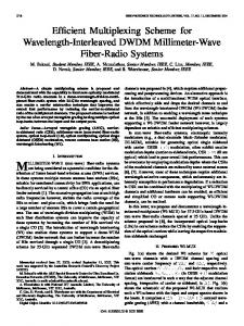
Fig. 1. Illustration of the suggested optical setup.
2. Morlet Mother Function
transform is defined as
W~a, b! 5
1 a
** `
`
2`
2`
S
f ~x, y!h*
D
x 2 b1 y 2 b2 dxdy, , a a (3)
where b5
FG
b1 . b2
Several methods have been proposed for optically obtaining the 2-D wavelet transform. One approach is based on the VanderLugt 4f configuration with a multireference-matched filter, in which each daughter wavelet is encoded with a different reference beam. The system provides several wavelet components that are spatially multiplexed.10,11 In this approach, the space–bandwidth product of the output plane has to be increased to arrange every wavelet component in a 2-D distribution. Another approach for performing a 2-D wavelet transform is based on the VanderLugt configuration with time multiplexing ~temporal replacement of the filter!. This method resulted in a nonreal-time configuration. The third approach for achieving a 2-D real-time wavelet transform is based on recycling the input through an optical correlator and using the magnification and reduction capabilities of optics to scale it ~instead of the mother wavelet functions!.12 In this paper we propose a novel method to obtain the 2-D wavelet transform indicated in Eq. ~3!. This is obtained with only one spatial channel and in real time. The different wavelet scales a are multiplexed with different wavelengths and incoherently added in the output plane. The method does not involves an increase in the resolution in the output plane, and an arbitrary number of components can be multiplexed in the same spatial extent of the input image. In Section 2 we introduce the Morlet wavelet mother function used in this project. In Section 3, we explain the suggested optical setup. In Section 4, we give experimental results. 7020
APPLIED OPTICS y Vol. 35, No. 35 y 10 December 1996
For the following discussion we used an approximated 2-D Morlet function7 as a mother function. The definition of the Morlet function is
S D
h~ x! 5 2 cos~2pf0 x!exp 2
x2 . 2
(4)
Such a wavelet was used by Martinet et al.7 in its 1-D form for sound-signal analysis. Its Fourier transform is H~u! 5 2p$exp@22p2~u 2 f0!2# 1 exp@22p2~u 1 f0!2%. (5) One can notice that this function is a real, nonnegative. Its 2-D extension has a circular Gaussian ring shape. In our optical experiments we have approximated the Morlet function to a rectangular ring
SÎ
H~u, v! < rect
D
u 2 1 v 2 2 f0 , W
(6)
where rect is the rectangular function and W is the width of the ring. Note that this function meets the zero dc requirement only when f0 is sufficiently large. 3. Experimental Implementation
The underlying idea in the proposed system is to obtain the different wavelet components with different wavelengths, i.e., wavelength multiplexing. The system is designed to provide all the components in the same spatial locations. The optical setup to perform the 2-D wavelet transform by use of wavelength multiplexing is illustrated in Fig. 1. In this setup the input pattern should be illuminated by several spatially coherent wavelengths. Several methods can be devised to provide this multilambda illumination. From the laboratory experimental point of view the simplest is the use of several collinear laser beams, each of them providing a perfectly coherent wavelength. A single multiline laser can produce the same result. Another option is the use of a spatially coherent white light source with an e´talon, which also produces a set of narrow-band illumination wavelengths, in this case with uniform spacing between them. With any of these procedures, a set
be at a location given by lij 5 z2 tan aij . z2 sin aij 5 z2
Fig. 2. Schematic illustration of the filter.
of wavelengths $l1, l2, . . . , lN; li , li11% is generated to illuminate the input object. The first part of the setup shown in Fig. 1 performs the Fourier transform of the input pattern. Using an achromatic lens obtains the same distribution for every wavelength in the illumination set. The Fourier transform for every wavelength is scaled inversely proportionately to l and appears in the same axial location. A filter is placed in the Fourier plane. The filter contains several rings, with each ring corresponding to the bandpass connected with the different scales of the Morlet mother function. In addition, the sizes of the different rings are scaled according to the ratio lNyli between the different wavelengths used in the input illumination. Filtering the Fourier transform of the input by the bandpass of the ring i ~obtained with li ! will produce the corresponding wavelet component. Numbering the rings from inside to outside by increases of the index i @with the i ring corresponding to the wavelength li ~li , li11!# results in rings that do not overlap among themselves. Gratings with different spatial frequencies are plotted inside each ring. A schematic illustration of the filter is given in Fig. 2. The ratio between the grating periods is as follows:
sin a 5
li , Ti
(7)
where a is the angle of the first diffraction order from the grating with period Ti when illuminated with li , and a is constant. This choice of period ensures that the different wavelength components li @ i diffracting from the respective i rings ~with period Ti @ i! are directed with the same angle ~a!. The second part of the system performs another Fourier transform. Considering a single wavelength, the whole system is just an off-axis imaging system. Because of the different periods in the rings of the filter, every range of spatial frequencies will be imaged in a different lateral position. The central position of the image produced by li by the ring j will
li . Tj
(8)
With the choice of periods of Eq. ~7! the locations of the images formed with every wavelength li through their respective rings i will coincide. Thus, in the output plane, at a location lii 5 l 5 z2 sin a, a chromatic superposition of the wavelet components, one of each wavelength, will be obtained. With the proper bias term for every wavelength, the output image will be reconstructed again in the output plane, whereas different spectral information ~different rings in the filter plane! will be encoded with different wavelengths. In addition to the superposition of the wavelet components, the separation between the desired output and other cross terms ~coming from the diffraction of li through other rings, j Þ i! should be enough to fit the reconstructed image. This situation imposes constraints over the minimum frequencies of the gratings or, alternatively, on the maximum size of the input. Denoting the size of the input object as S and using the fact that the magnification between the input and output planes is z2yz1, we find that the distance between the output ~located at lii! and any cross term ~located at ljk! should fulfill
S D
lii 2 ljk 5 z2 1 2
lj z2 sin a $ S ; ~ j, k!. lk z1
(9)
In the case of a uniform spacing of the frequencies, condition ~9! can be simplified to TN #
z1Dl , S
(10)
where Dl 5 uli 2 li21u is the difference between two sequential wavelengths. Condition ~10! provides a restriction for the maximal value of the period of the gratings. Note that, in principle, an arbitrary number of wavelet components can be achieved with this method. The only technical restrictions are the number of available wavelengths and the maximum frequency that can be recorded on the filter. When experiments are involved, the theoretical assumption that a laser has a single illuminating wavelength is no longer valid. Assume that the laser’s illumination has an illuminating bandwidth of dli for each wavelength li . Then, using expression ~9!, one may obtain the smear dl in the output plane that is due to this bandwidth: dl 5
z2dli sin a . li
(11)
Thus, the number of degrees of freedom Ndl obtained in the image of the output plane is the ratio between the smear size and the size of the output 10 December 1996 y Vol. 35, No. 35 y APPLIED OPTICS
7021
image ~z2Syz1!: Ndl 5
z2Syz1 . dl
(12)
Using the relations of Eq. ~7! and condition ~10!, Ti 5 sin a 5
z1Dl , S
(13)
li , Ti
(14)
and Eqs. ~11! and ~12!, one obtains Ndl 5
Dl . dli
(15)
Thus, the space-bandwidth product SW of the system is SW 5 min$N, Ndl%,
(16)
where N is the number of degrees of freedom ~number of pixels! in the original image. The above-presented setup is not the only possible one. Instead of using the dispersion of a grating to separate the components, a thick hologram may be used. A thick transmission hologram is angular sensitive. Hence the lateral location of the input is critical, which means it is highly space variant. However, when a thick reflection hologram is used the obtained result is highly wavelength sensitive and weakly position sensitive, which is mostly desirable. The recorded multiple-reflection hologram plays the triple role of selecting the spatial frequencies for every wavelet component, transforming a broadband illumination in a set of wavelengths, and eliminating the cross terms. This setup consists of a thick hologram positioned at the location at which every wavelet has been recorded in the Fourier plane with a different wavelength. For monochromatic illumination the hologram will reflect only one component, but when illuminated with white light all the components are reconstructed simultaneously. Proper selection of the carrier frequencies will produce the desired overlap between the components. Moreover, because of the selectivity of the hologram, the reconstructed beam in a certain l will not produce cross talk with the other wavelets, which are recorded with a different carrier frequency in the volume hologram. This approach is a future direction which is now under investigation. 4. Experimental Results
To demonstrate the operating ability of the system we have prepared a filter with two rings. Each ring has a different grating corresponding to one of the two wavelength illuminations: a doubled Nd:Yag laser ~l 5 532 nm! and a red He–Ne laser ~l 5 632.8 nm!. The illumination coming from the two lasers is input into the setup as a single beam by the use of a beam splitter. The periods of the gratings were T1 5 10 7022
APPLIED OPTICS y Vol. 35, No. 35 y 10 December 1996
Fig. 3. Output obtained using the Roseta input: ~a! with colored input illumination, ~b! with red-only illumination, and ~c! with green-only illumination.
mm and T2 5 11.895 mm. The filter was printed with a Scitex Dolev plotter and photoreduced on a lithographic film. Two patterns were used as input. The first pattern is a “Roseta” pattern. This is a pattern with symmetry around the origin and spatial frequencies that decrease monotonously with the radius. The obtained output is illustrated in Fig. 3~a!. Figures 3~b! and 3~c! show the output when only red or green illumination, respectively, is used. The second input pattern was the “Lenna” image. Once again, Fig. 4~a! illustrates the output obtained by the use of both illumination wavelengths. Figures 4~b! and 4~c! show the output when only red or green illumination, respectively, is used. One can see that, indeed, in Fig. 4~a! more spatial frequencies are reconstructed as compared with the use of only one wavelength for illumination. 5. Conclusions
In this paper a novel method for obtaining a 2-D wavelet transform has been suggested. The new approach uses wavelength multiplexing to transmit simultaneously the information related to different scales of the wavelet function. At the output, the information transmitted by means of the different wavelengths is added incoherently, and the original image pattern may be formed. The promising experimental results illustrate that this method of wavelet multiplexing can be successfully used for both image processing and communication transmittance applications. Note that the demonstrated experiment was performed with the Morlet wavelet mother function. Obviously, other mother functions ~e.g., the Mexican-hat mother wavelet function! may be used as well. Z. Zalevsky acknowledges the Eshcol Fellowship granted by the Israelian Ministry of Science and Arts. J. Garcia acknowledges a grant from the Universitat de Vale`ncia. This work was partially supported by the Spanish Comision Interministerial de Ciencia y Tecnologı´a under project TAP 93-0667-103-03. References
Fig. 4. Output obtained using the Lenna input: ~a! with colored input illumination, ~b! with red-only illumination, and ~c! with green-only illumination.
1. D. Gabor, “Theory of communication,” J. Inst. Electr. Eng. 93, 429 – 457 ~1946!. 2. M. J. Bastiaans, “Gabor’s signal expansion and the Zak transform,” Appl. Opt. 33, 5241–5250 ~1994!. 3. H. Szu, Y. Sheng and J. Chen, “Wavelet transform as a bank of matched filters,” Appl. Opt. 31, 3267–3277 ~1992!. 4. J. M. Combes, A. Grossmann, and Ph. Tchamitchian, eds., Wavelets: Time Frequency Methods and Phase Space, 2nd ed. ~Springer-Verlag, Berlin, 1990!. 5. X. J. Lu, A. Katz, E. G. Kanterakis, and N. P. Caviris, “Joint transform correlation using wavelet transforms,” Opt. Lett. 17, 1700 –1703 ~1992!. 6. J. Caulfield and H. Szu, “Parallel discrete and continuous wavelet transforms,” Opt. Eng. 31, 1835–1839 ~1992!. 7. R. K. Martinet, J. Morlet, and A. Grossmann, “Analysis of sound patterns through wavelet transforms,” Int. J. Pattern Recog. Artif. Intell. 1, 273–302 ~1987!. 8. E. Freysz, B. Pouligny, F. Argoul, and A. Arneodo, “Optical wavelet transform of fractal aggregates,” Phys. Rev. Lett. 64, 7745–7748 ~1990!. 10 December 1996 y Vol. 35, No. 35 y APPLIED OPTICS
7023
9. I. Daubechies, “The wavelet transform time–frequency localization and signal analysis,” IEEE Trans. Inf. Theory 36, 961– 1005 ~1990!. 10. D. Mendlovic, I. Ouzieli, I. Kiryuschev, and E. Marom “Twodimensional wavelet transform achieved by computergenerated multireference matched filter and Dammann grating,” Appl. Opt. 34, 8213– 8219 ~1995!.
7024
APPLIED OPTICS y Vol. 35, No. 35 y 10 December 1996
11. D. Mendlovic and N. Konforti, “Optical realization of the wavelet transform for two-dimensional objects,” Appl. Opt. 32, 6542– 6546 ~1993!. 12. M. O. Freeman, K. A. Duell, and A. Fedor, “Multi-scale optical image processing,” paper presented at the “IEEE International Symposium on Circuits and Systems,” June 1991, Singapore.