Two-Part Reconstruction in Compressed Sensing Yanting Ma,∗ Dror Baron,∗ and Deanna Needell† ∗ Department
arXiv:1306.5776v2 [cs.IT] 11 Sep 2013
of Electrical and Computer Engineering North Carolina State University; Raleigh, NC 27695, USA Email: {yma7, barondror}@ncsu.edu † Department of Mathematical Sciences Claremont McKenna College; Claremont, CA 91711, USA Email:
[email protected]
Abstract—Two-part reconstruction is a framework for signal recovery in compressed sensing (CS), in which the advantages of two different algorithms are combined. Our framework allows to accelerate the reconstruction procedure without compromising the reconstruction quality. To illustrate the efficacy of our two-part approach, we extend the author’s previous Sudocodes algorithm and make it robust to measurement noise. In a 1bit CS setting, promising numerical results indicate that our algorithm offers both a reduction in run-time and improvement in reconstruction quality. Index Terms—compressed sensing, fast algorithms, two-part reconstruction.
I. I NTRODUCTION In the compressed sensing (CS) signal acquisition paradigm, sparse signals xN ∈ RN containing only K ≪ N nonzero coefficients can be reconstructed from measurements y ∈ RM with K < M ≪ N [1, 2]. The measurement system is often modeled as a linear matrix-vector multiplication y = Φx; measurement noise can also be supported, y = Φx + z. While reconstruction quality is an important criterion for designing reconstruction algorithms, the run-time is also of great concern in practical applications. Prior art: There is a vast literature on CS signal reconstruction algorithms; many existing algorithms can be classified as combinatorial or geometric. The combinatorial approach uses sparse and often binary measurement matrices [3, 4], and features fast recovery but requires a suboptimal number of measurements. Sparse binary measurement matrices based on expander graphs have been shown to have good properties for compressed sensing reconstruction problems [5]. The geometric appoach uses dense measurement matrices that satisfy the Restricted Isometry Property (RIP) [2]. Examples of the geometric approach include CoSaMP [6] and IHT [7]. The advantages of the geometric approach are that it requires a small number of measurements and offers resiliency to measurement noise at the expense of greater run-time [8]. The Sudocodes algorithm [9] provides a new scheme for lossless reconstruction of sparse signals in the case where measurements are noiseless. The algorithm has two parts. In Part 1, the Sudocodes algorithm [9] uses a sparse binary random matrix with L ones in each row to acquire the measurements. Therefore, only L summation operations are needed for the acquisition of each measurement. With these measurements, Part 1 can efficiently recover most of the zero
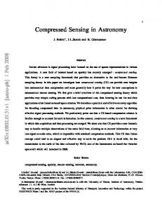
coefficients and some of the nonzero coefficients in x. After Part 1, only a modest number of coefficients are unknown, and the unknown coefficients are solved in Part 2, where a dense measurement matrix is used. Part 2 first updates the components in the measurements and measurement matrix that are related to the coefficients recovered in Part 1. Therefore, Part 2 only needs a modest number of measurements and it applies matrix inversion to solve the remaining reconstruction problem. A variation of the Sudocodes algorithm is group testing basis pursuit CS (GBCS) [10], which applies a CS reconstruction algorithm, Basis Pursuit, in Part 2. Sudocodes and GBCS are both fast. However, they can only be applied to the noiseless case, which is impractical in many real life applications. Nonetheless, the idea of two-part reconstruction motivates a more practical framework, which performs fast reconstruction in the presence of noise. Unlike Sudocodes, a more straightforward approach to two-part reconstruction is to perform support recovery in Part 1 [11], but exact support recovery is ambitious, especially when the measurements are noisy. Contributions: First, we propose a two-part framework for reconstruction of sparse signals (Section II-A). The purpose of our framework is to accelerate the reconstruction procedure without compromising the reconstruction quality. Our strategy is to let Part 1 perform a simple algorithm to provide partial reconstruction and let Part 2 complete the residual reconstruction problem. Second, to illustrate the efficacy of our two-part approach, we extend the Sudocodes algorithm [9] and make it robust to measurement noise (Section II-B); we call this algorithm Noisy-Sudocodes. Third, we apply NoisySudocodes to 1-bit CS, by using a modified 1-bit quantizer in Part 1 and Binary Iterative Hard Thresholding (BIHT) [12] in Part 2 (Section II-C). Promising numerical results (Section III) indicate that our algorithm offers both a reduction in run-time and improvement in reconstruction quality. II. T WO - PART RECONSTRUCTION A. Framework We discuss our two-part reconstruction framework, which is illustrated in Figure 1. Part 1 will apply a simple and fast algorithm. This algorithm will quickly provide a low quality reconstruction in the sense that for some portion of the coefficients, it may not be able to perform sufficiently accurate reconstruction. The index set of the coefficients that are not
accurately reconstructed in Part 1 will then be sent to Part 2. On the one hand, in order to reduce the run-time, we want the portion left for Part 2 to be as small as possible, because the algorithm in Part 2 is in general more complex and slower than the algorithm in Part 1. On the other hand, we don’t want to sacrifice too much accuracy. The trade-off between reconstruction quality and run-time can be adjusted according to the specifics of the application at hand. Similar to the original Sudocodes algorithm [9], Part 2 will only deal with the coefficients that are left over from Part 1. Part 2 will first remove the redundant coefficients in x whose indices are not in the index set sent by Part 1, and also remove the corresponding columns from the measurement matrix. The measurements are then updated by subtracting the contribution of the removed coefficients to the original measurements. Because the problem size is greatly reduced in Part 2, the algorithm applied in Part 2 can put emphasis on reconstruction quality rather than run-time. A potential drawback of our twoInput measurements & measurement matrix in Part 1
Input measurements & measurement matrix in Part 2
Simple algorithm
Low quality reconstruction in Part 1
Update measurements & measurement matrix in Part 2 High fidelity algorithm
Combine the reconstructed signals from Part 1 and Part 2
High quality reconstruction in Part 2
Output of two-part reconstruction
because it is a simple low quality algorithm. The index set T can now be defined as: T , {i: x(i) is not recovered in Part 1}. Define (x)T , {x(i) ∈ x: i ∈ T }. Let (Φ)T denote the submatrix formed by combining columns of Φ at column indices T . We define Ωr (j) as the support (indices of nonzeros) of the jth row of Φ1 , and Ωc (i) as the support of the ith column of Φ1 , where j ∈ {1, ..., M1 } and i ∈ {1, ..., N }. The Noisy-Sudocodes algorithm proceeds as follows: Part 1: The measurement matrix Φ1 has independent and identically distributed (i.i.d.) Bernoulli entries. The measurement vector y1 is acquired via (1), and each y1 (j) is the summation of a subset of coefficients of x that depend on Ωr (j). If there is no measurement noise, as in the Sudocodes algorithm [9], then for a real-valued input x, a zero measurement can only be the summation of zero coefficients. In other words, if y1 (j) is zero, then (x)Ωr (j) = 0. But in the presence of noise, a measurement is (very) unlikely to be precisely zero. Moreover, a small-valued measurement could have measured a combination of multiple large-valued coefficients, though with small probability p. However, it is unlikely that a large-valued coefficient could appear in multiple small-valued measurements (if p is small, then pn decreases quickly as n increases). Our numerical experiments suggest that if the measurement matrix is sparse enough, then it is sufficiently accurate to identify a coefficient to be zero when it is involved in three or more small-valued measurements. To utilize this numerical observation, let ǫ be a small positive constant that depends on the noise level. Define an index set that contains the indices of small-valued measurements as: S , {j : |y1 (j)| < ǫ, j ∈ {1, ..., M1}}.
Fig. 1. Block diagram for two-part reconstruction.
part framework is that in order for Part 1 to identify most of the coefficients correctly, it might be necessary to use an increased number of measurements. Therefore, our two-part framework is mostly applicable when fast reconstruction is crucial whereas measurements are relatively cheap. B. Noisy-Sudocodes To illustrate how two-part reconstruction can combine the advantages of two algorithms, we describe a Noisy-Sudocodes algorithm, which extends the original Sudocodes algorithm [9] by making it robust to measurement noise, while retaining the high-speed processing of the original algorithm. We begin with some notations. Let x be the real-valued input signal and let x(i) represent the ith element of x. Denote the measurement matrices in Part 1 and Part 2 by Φ1 ∈ RM1 ×N and Φ2 ∈ RM2 ×N , respectively. Let z1 and z2 represent additive measurement noise; the noisy measurements in the two parts are given by: y 1 = Φ1 x + z 1 ,
(1)
y 2 = Φ2 x + z 2 .
(2)
The reconstructed signal obtained from Part 1 is denoted by x b1 . Note that not all the coefficients are recovered in Part 1,
(3)
We identify x(i), i ∈ {1, ..., N } to be zero if |Ωc (i) ∩ S| ≥ 3, where |·| denotes cardinality. For those coefficients that cannot be identified in this zero-identification procedure, the indices are recorded in T and sent to Part 2. Part 2: Solve the remaining reconstruction problem by utilizing a high quality CS reconstruction algorithm. The distribution of the measurement matrix Φ2 depends on the algorithm applied in Part 2 (for example, if CoSaMP [6] is used in Part 2, then a Gaussian Φ2 is appropriate). Initially, the measurement vector y2 is acquired via (2). After receiving T from Part 1, Part 2 first updates x and Φ2 : x e = (x)T , e 2 = (Φ2 )T . Φ
Note that we only identify zero coefficients in Part 1. The zero coefficients do not contribute to y2 , thus y2 need not be updated. The high quality CS reconstruction algorithm in e 2 , and y2 , and computes x Part 2 takes x e, Φ b2 , the reconstructed signal. We complete the reconstruction by assigning the coefficients in x b2 at indices T to the elements in the final reconstructed signal x b, (b x)T = x b2 .
(4)
y = sign(Φx + z),
(5)
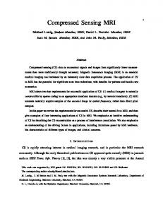
where z is measurement noise. Note that the measurements acquired in both noiseless and noisy 1-bit CS include quantization noise. The quantization noise explains why the SNR achieved in the noiseless 1-bit CS setting, which is shown in Figure 2, is finite, whereas unquantized noiseless measurements yield perfect reconstruction [1, 2]. Because the amplitude information of the measurements is lost due to the quantization described by (4) or (5), it is convenient to assume that the 1-bit CS framework imposes a unit energy constraint on the reconstructed signal. In Part 1 of Noisy-Sudocodes discussed in Subsection II-B, we only need to know if y1 (j) is greater or less than ǫ. Therefore, 1 bit is sufficient to quantize each measurement without losing any information needed for the reconstruction in Part 1. For example, we can quantize y1 (j) as: ( 0, if |y1 (j)| ≤ ǫ y¯1 (j) = . (6) 1, if |y1 (j)| > ǫ We note that this modified 1-bit quantizer (6) is only used in Part 1, whereas in Part 2 we utilize a standard 1-bit quantizer (4, 5). Then utilizing y¯1 as the measurements, (3) can be rewritten as: S , {j : |¯ y1 (j)| = 0, j ∈ {1, ..., M1}}. This discussion implies that Noisy-Sudocodes can be extended to a 1-bit CS setting by utilizing a 1-bit CS algorithm in Part 2. A possible 1-bit CS algorithm that can be utilized is BIHT [12]. BIHT achieves better reconstruction performance than the previous 1-bit CS algorithms in the noiseless 1bit CS setting. We show by numerical results in Section III that combining Noisy-Sudocodes with BIHT in a two-part setting (Sudo+BIHT) achieves better reconstruction quality and reduction in run-time than directly using BIHT (direct BIHT). III. N UMERICAL RESULTS In this section, we present simulation results that compare Sudo+BIHT and direct BIHT in terms of SNR and run-time. SNR is defined as SNR(dB) , 10 log10 (kxk22 /kx − x bk22 ),
where x is the input signal and x b is the reconstructed signal; run-time is measured in seconds on a Dell OPTIPLEX 9010 running an Intel(R) CoreTM i7-3770 with 16GB RAM. We simulate both noiseless, in which BIHT-l1 is utilized and noisy 1-bit CS settings, in which BIHT-l2 is utilized. The input signal x is of length N = 10, 000, containing K = 50 nonzero coefficients, which are i.i.d. Gaussian with
50
SNR(dB)
y = sign(Φx),
zero mean, and x is normalized such that kxk2 = 1. Let M1 and M2 be the number of measurements for Parts 1 and 2 of Sudo+BIHT. Then M = M1 + M2 is the number of measurements for direct BIHT. We perform the trials for measurement rate M/N within the range [0, 2]. In our simulation, we let M1 = c1 K log2 (N/K), which for sufficiently large c1 (determined numerically) allows Part 1 to identify more than 90% of the zero coefficients. The measurement matrix Φ1 ∈ RM1 ×N is i.i.d. Bernoulli with Bernoulli parameter p = cK2 , where c2 (determined numerically) is a constant. Note that the nonzero entries of the Bernoulli matrix are scaled by √1 in order to have the same input SNR as in direct BIHT. p Φ2 ∈ RM2 ×N is i.i.d. Gaussian with φ2 (i, j) ∼ N (0, 1), i ∈ {1, ..., M2 }, j ∈ {1, ..., N }. For direct BIHT, the measurement matrix Φ ∈ RM×N is i.i.d. Gaussian with φ(i, j) ∼ N (0, 1), i ∈ {1, ..., M }, j ∈ {1, ..., N }. Finally, the additive measurement noise z, which we use in the noisy setting, is i.i.d. Gaussian. It has zero mean and its variance is 10−2.5 . Noiseless setting: The measurement vector y1 for Part 1 of Sudo+BIHT is acquired by (6) with ǫ = 0, and the measurement vectors y2 for Part 2 of Sudo+BIHT and y for direct BIHT are acquired by (4). In the noiseless setting, if any element y1 (j) only measures zero coefficients, then y1 (j) will be strictly zero. Therefore, we modify Part 1 of NoisySudocodes by identifying x(i) to be zero if it is measured at least once in the zero measurements, i.e., |Ωc (i) ∩ S| ≥ 1. Note that in this case, Part 1 will not introduce any error.
40 30
Sudo+BIHT direct BIHT
20 10
0
0.5
1
1.5
2
1.5
2
M/N 150
run−time(sec)
C. Application to 1-bit compressed sensing In 1-bit CS [13], the CS measurements are quantized to 1 bit per measurement. The problem model for noiseless and noisy 1-bit CS is formulated as
direct BIHT Sudo+BIHT
100
50
0
0
0.5
1
M/N
Fig. 2. Reconstruction performance from 1-bit measurements in the noiseless setting.
The simulation results for the SNR and run-time are shown in Figure 2. We iterate over BIHT until the consistency property1 is satisfied or the number of iterations reaches 100. We notice 1 We say that the consistency property of BIHT [13] is satisfied if applying the measurement and quantization system (4) and (5) to the reconstructed signal x b yields the same measurements y as the original measurements.
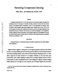
that Sudo+BIHT achieves slightly higher SNR than direct BIHT except in the low measurement rate (M/N ) region, where the SNR for both Sudo+BIHT and direct BIHT is modest. Owing to the generally low reconstruction quality in the low measurement rate region, it is more interesting to compare performance in the higher measurement rate region. It is demonstrated in Figure 2 that as M/N increases, the SNR for both algorithms increases similarly. However, the run-time for Sudo+BIHT grows slower than direct BIHT. Noisy setting: The measurement vector y1 for Part 1 of Sudo+BIHT is acquired by (6) with ǫ > 0, and the measurement vectors for Part 2 of Sudo+BIHT, y2 , and direct BIHT, y, are acquired by (5). The resulting SNR is shown in 30
25
SNR(dB)
20
15
10
Sudo+BIHT 130 direct BIHT 130 Sudo+BIHT 80 direct BIHT 80 Sudo+BIHT 30 direct BIHT 30
5
0
−5
0
0.5
1
1.5
2
Fig. 3. SNR achieved by Sudo+BIHT and direct BIHT in the noisy 1-bit CS setting with 30, 80 and 130 iterations for BIHT.
250
direct BIHT 130 direct BIHT 80 direct BIHT 30 Sudo+BIHT 130 Sudo+BIHT 80 Sudo+BIHT 30
run−time(sec)
150
100
50
0
0
0.5
1
1.5
IV. CONCLUSION We discussed a two-part framework for fast reconstruction of sparse signals, in which Part 1 quickly reduces the problem size by reconstructing the “easy” part, leaving a “difficult” problem of smaller size for Part 2. The zero-identification algorithm in Noisy-Sudocodes is well suited for Part 1 of our two-part framework, because it is fast. Part 1 of NoisySudocodes quickly identifies most of the zero coefficients without introducing much error. Therefore, a high fidelity algorithm in Part 2 is able to complete the reconstruction efficiently due to the reduction in problem size. The promising simulation results of Noisy-Sudocodes with BIHT in Part 2 (Sudo+BIHT) implies that Noisy-Sudocodes could be promising for algorithm design in 1-bit CS reconstruction problems. R EFERENCES
M/N
200
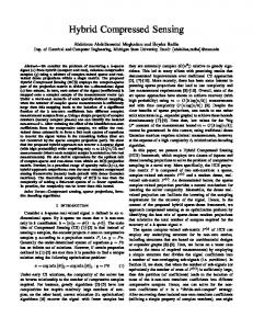
direct BIHT, Sudo+BIHT yields better consistency and thus provides better reconstruction quality. With more iterations, the SNR for both Sudo+BIHT and direct BIHT improves. The SNR curve of direct BIHT tends to get closer to Sudo+BIHT as the number of iterations increases, because for Sudo+BIHT, the error introduced in Part 1 cannot be corrected by Part 2. We notice that the run-time for Sudo+BIHT with 130 BIHT iterations is half of that for direct BIHT with 30 BIHT iterations, while the SNR increased by roughly 5 dB. In other words, problem size reduction due to zero identification in Part 1 allows BIHT in Part 2 to run more iterations to improve reconstruction quality with reasonable run-time.
2
M/N
Fig. 4. Run-time of Sudo+BIHT and direct BIHT in the noisy 1-bit CS setting with 30, 80 and 130 iterations for BIHT.
Figure 3, and run-time is shown in Figure 4. When the number of iterations for BIHT is 30 in both Part 2 of Sudo+BIHT and
[1] D. Donoho, “Compressed sensing,” IEEE Trans. Inf. Theory, vol. 52, no. 4, pp. 1289–1306, Apr. 2006. [2] E. Cand`es, J. Romberg, and T. Tao, “Robust uncertainty principles: Exact signal reconstruction from highly incomplete frequency information,” IEEE Trans. Inf. Theory, vol. 52, no. 2, pp. 489–509, Feb. 2006. [3] P. Indyk, “Explicit constructions for compressed sensing of sparse signals,” in Proc. 19th ACM-SIAM Symp. Discrete Algos., Jan. 2008, pp. 30–33. [4] M. A. Iwen, “Compressed sensing with sparse binary matrices: Instance optimal error guarantees in near-optimal time,” CoRR, vol. abs/1302.5936, Feb. 2013. [5] S. Jafarpour, W. Xu, B. Hassibi, and R. Calderbank, “Efficient and robust compressed sensing using optimized expander graphs,” IEEE Trans. Inf. Theory, vol. 55, no. 9, pp. 4299–4308, Sep. 2009. [6] D. Needell and J. A. Tropp, “CoSaMP: Iterative signal recovery from incomplete and inaccurate samples,” Appl. Comput. Harm. Anal., vol. 26, no. 3, pp. 301–321, May 2009. [7] T. Blumensath and M. E. Davies, “Iterative hard thresholding for compressed sensing,” Appl. Comput. Harm. Anal., vol. 27, no. 3, pp. 265–274, Nov. 2009. [8] R. Berinde, A. C. Gilbert, P. Indyk, H. Karloff, and M. J. Strauss, “Combining geometry and combinatorics: A unified approach to sparse signal recovery,” in Proc. 46th Annual Allerton Conf. Comm., Control, Computing, Sept. 2008, pp. 798–805. [9] S. Sarvotham, D. Baron, and R. G. Baraniuk, “Sudocodes – Fast measurement and reconstruction of sparse signals,” in Proc. Int. Symp. Inf. Theory (ISIT2006), Seattle, WA, July 2006. [10] A. Talari and N. Rahnavard, “GBCS: A two-step compressive sensing reconstruction based on group testing and basis pursuit,” in Military Comm. Conf., Nov. 2011, pp. 157–162. [11] S. Gopi, P. Netrapalli, P. Jain, and A. Nori, “One-bit compressed sensing: Provable support and vector recovery,” in ICML ’13: Proc. 30th Int. Conf. Machine learning, Jun. 2013. [12] L. Jacques, J. N. Laska, P. T. Boufounos, and R. G. Baraniuk, “Robust 1bit compressive sensing via binary stable embeddings of sparse vectors,” IEEE Trans. Inf. Theory, vol. 59, Apr. 2013. [13] P. Boufounos and R. Baraniuk, “1-bit compressive sensing,” in Proc. 2008 Conf. Inf. Sciences Systems, Mar. 2008, pp. 16–21.