Publications
5-4-2015
UAS Capabilities and Performance Modeling for Application Analysis Brent Terwilliger Embry-Riddle Aeronautical University,
[email protected]
Dennis Vincenzi Embry-Riddle Aeronautical University,
[email protected]
David Ison Embry-Riddle Aeronautical University,
[email protected]
Rene Herron Embry-Riddle Aeronautical University,
[email protected]
Todd Smith Embry-Riddle Aeronautical University,
[email protected]
Follow this and additional works at: http://commons.erau.edu/publication Part of the Navigation, Guidance, Control and Dynamics Commons Scholarly Commons Citation Terwilliger, B., Vincenzi, D., Ison, D., Herron, R., & Smith, T. (2015). UAS Capabilities and Performance Modeling for Application Analysis. , (). Retrieved from http://commons.erau.edu/publication/493
This Conference Proceeding is brought to you for free and open access by Scholarly Commons. It has been accepted for inclusion in Publications by an authorized administrator of Scholarly Commons. For more information, please contact
[email protected].
US15-TERWILLIGER
UAS CAPABILITIES AND PERFORMANCE MODELING FOR APPLICATION ANALYSIS Brent Terwilliger,* Dennis Vincenzi,t David Ison,* Rene Herron,§ and Todd Smith** Our team of researchers from Embry-Riddle Aeronautical UniversityWorldwide has been actively compiling published performance data associated with commercially-off-the-shelf (COTS) group 1 to 3 fixed-wing and vertical takeoff and landing (VTOL) unmanned aircraft systems (UAS) in an effort to develop statistical models of each category. The captured data, which includes maximum speed, cruise speed, endurance, weights, wind limitations, and costs, is used to calculate capabilities including range (one-way and return), time to objective, station keeping duration, maneuver requirements, and derive limited missing information (e.g., component speeds and weights). The benefit from assembling suc h a unified collection of information and the calculation of associated derived capabilities is that these models are anticipated to accurately reflect the capabilities, limitations, and considerations necessary in the assessment of such platforms for various applications and operating environments. These models will be available for combination with simulation or analyses to better assess end usability of these categories of aircraft for a significant number of applications including, emergency response, disaster relief, precision agriculture, security, tactical , communications, environmental study, infrastructure inspection, cargo delivery, and mapping/surveying.
INTRODUCTION New applications for unmanned aircraft systems (UAS) are being established at an increasing rate in connection with technological advances, operational enhancements, and improved capabilities awareness.1-2 Some uses of this technology are typical (e.g., open air operations such as infrastructure inspection or agriculture operations), 2 ·3 while others, including emergency response, are more limited due to location and airspace restrictions. The integration and implementation of new technology into UAS operations and application requires practice, planning, and experimentation to ascertain optimal system configuration based on known capabilities, performance, environmental factors, and operational needs. Being able to plan, visualize, and incorporate as many such known variables into a viable model for evaluation, training, and simulation purposes is key to ensuring operational safety, efficiency, and effectiveness.
· Program Chair, MS in Unmanned Systems, ERAU-Worldwide, Orlando, FL. Department Chair, Undergraduate Studies, College of Aeronautics, ERAU-Worldwide, Daytona Beach, FL. t Research Chair, Co ll ege of Aero naut ics, ERAU-Worldwide, Portland, OR. §Associate Program Chair, BS in Emergency Services, ERAU-Worldwide, Daytona Beach, FL. .. Program Chair, MS in Occupational Safety Management, ERAU-Worldwide, Atlanta, GA t
57 1
Researchers have recognized the criticality of performing in-depth analyses of the UAS configuration and environment, before initiating operations .~- The results of analysis provide potential users with the ability to examine, plan, visualize, and familiarize themselves with employment of various UAS technologies to best support intended use and maintenance of safety. 7·9 Additionally, contingency preparation and mission planning can be strengthened based on accurate use of likely conditions and relevant factors, including weather; time of day; personnel on duty; training and certification of users; system capability; sizing and placement of routes, orbits, and waypoints; equipment staging locations; requisite sensor packages; and mission parameters. 1· 10 9
Benefit UAS can provide significant benefit to users and the public, including enhancement of capability and reduced potential for hann, especially in those scenarios that involve removing personnel from dangerous environments or requiring performance of high risk actions. 2•3· 11 • 12 UAS enable and support expedited response to emergency scenes; remain aloft for significant periods; capture data from dynamic and elevated perspectives, while en-route and over scene; operate in dangerous environments; and relay critical information to those in command of coordinated efforts .7-9 Despite these potential advantages, numerous tradeoff considerations must be made against known limitations, including endurance, range, speed, payload capacity, ability to operate in inclement weather, and budget, to ensure optimal advantage, while reducing potential risk to persons, property, or ability to complete the mission. 6-8
Challenges The current U.S. regulatory framework for operation of UAS, established by the Federal Aviation Administration (FAA), requires review and approval of proposed operations through award of a certificate of waiver or authorization (COA), special airworthiness certificate-experimental category (SAC-EC), or type and airworthiness restricted category. 13 In February of 2015, the FAA released a notice of proposed rulemaking (NPRM) to amend current regulations to pennit limited operation of small UAS (sUAS; under 55 pounds), given they are operated by a pilot in command (PIC) who has successfully completed an aeronautical knowledge-exarnination. 3 While flights under NPRM amendments are envisioned to enhance user capability they will still present significant limitation to support activities such as emergency response by not pennitting operations outside of daylight, visual flight rule (VFR), or visual line of sight (VLOS) conditions. 3 It is possible that the proposed rules will be further amended to permit such operations through individual exemption or waiver for those that can demonstrate risk mitigation using enabling technologies or methods in a manner similar to how Section 333 COA petitions are reviewed and approved (i.e., enhancement of command and control through advanced human machine interfaces [HMis] or detect, sense, and avoid [DSA]). 3 · 14 The effectiveness of such an exemption or waiver process will require provision of capability exceeding that proposed under the current NPRM 3 and the recently released FAA interim policy of Section 333 exemption COA holders to fly "anywhere in the country except restricted airspace and other areas, such as major cities, where the FAA prohibits UAS operations" (para. 3). 15 Identifying and integrating new UAS technology and techniques into applications, such as emergency response, requires thorough review and considerations of regulatory compliance, capabilities, limitations, challenges, benefits, and environment to ascertain optimal system configuration and development of an appropriate concept of operation (CONOP). 4 6 -7 Such review can be accomplished through analysis of known metrics associated with UAS performance, regulatory and operational requirements, and environmental factors exhibited or evidenced in past operation, research, or survey. Examples include perfonnance of risk, cost-benefit, system, environmental, perfonnance, and electromagnetic propagation assessments:" 6 · 8 Achieving optimal UAS capabil-
572
ities, such as in support of emergency aviation response, requires planning and configuration of applicable components to provide appropriate situational awareness (i.e., spatial and state representation) to the respective user in an intuitive, flexible, adaptable, and standardized manner. 9·16 By achieving an improved understanding of the limitations and constraints of the UAS configuration, HMis, and CONOP it is anticipated that operational safety, efficiency, and effectiveness can be established and maintained, thereby reducing the potential for accident or harm. PURPOSE Determining applicability and suitability of specific UAS platforms to perform given tasks or missions requires thorough review and analysis prior to selection, acquisition, and operation of the system.~· · · Performing effective analysis requires the capture and provision of prerequisite information inputs detailing the attributes of candidate platforms relating to the intended use, such as capabilities and constraints .8· 10 · 11 In support of this need, the research team endeavored to capture or derive performance data of commercially-off-the-shelf (COTS) group 1 to 3 fixed-wing and vertical takeoff and landing (VTOL) UAS to develop statistical performance models of each category (base group 1-3 categories and assignment attributes based on Department of Defense [DOD] UAS organizational schema 18). This captured data, which includes maximum speed, cruise speed, endurance, weights, wind limitations, and costs, is intended to be used in analysis to calculate capabilities including range (one-way and return), time to objective, station keeping duration, and maneuver requirements. The benefit from assembling such a unified collection of information and the calculation of associated derived capabilities is that the resulting category representative UAS performance models are anticipated to accurately reflect the capabilities, limitations, and considerations necessary in the assessment of such platforms for various applications and operating environments. These models will be available for combination with simulation or analyses to better assess end usahility of these categories of aircraft for a significant number of uses including, emergency response, disaster relief, precision agriculture, security, tactical, communications, environmental study, infrastructure inspection, cargo delivery, mapping, and surveying. 7 9 1 1
To determine the potential use of such UAS performance models an example application analysis framework specific to aircraft rescue and fire fighting (ARFF) response was developed and tested. This initial effort represents a case study into the potential effectiveness of such models to support development of application unique platform requirements, refinement of an initial theory of operation, and improvement of analysis methods. The intent was to observe and document the utility of employing UAS statistical models for use in evaluating suitability for application, effectiveness of platforms, and identification of important limitations, constraints, or attributes. RESEARCH At the initiation of this project a multiple stage research and development plan was created and implemented to study and analyze potential UAS platform configuration performance for given applications. This plan was constructed in a manner supporting initial development, further refinement, incorporation of new information, and performance of validation and verification of findings. This approach supported the initial investigation and development of category representative UAS performance models, an application analysis framework, and other requisite elements; theory of operation, 30 experimental trial scenarios, and assumptions. As UAS exhibit many attributes and characteristics perceived to be beneficial to ARFF response, this application was selected as a case for initial use of category representative UAS performance models to support investigation and analysis into their potential effectiveness and the capability of the UAS configuration to perform the desired task. The intent was to determine what category and type of
573
UAS would best support envisioned emergency response operations and compare to conventional ARFF response to reach the accident site. At the conclusion of this stage of the research, possible avenues for model and framework refinements and the capture, derivation, and incorporation of further data were examined and identified.
Category Representative UAS Performance Models The development of category representative UAS perfonnance models , tenned attribute performance models (APMs) in this context, required the investigation, capture, and derivation of metrics based on published capabilities of platform configurations. Initially, 180 COTS UAS platform configurations (30 per category) were examined. However, with progression of the project, the sample size of UAS platfonn configurations was expanded to 282 (45-56 per category; total of 268 unique airframes; see explanation in subsequent text) to improve accuracy and fideli ty. The associated metrics (attributes) of the UAS configurations were captured through review of publicly available literature, communication with manufacturers, and derived based on related attributes to create statistical UAS performance models (APMs) later used in the experiment and final analysis. The elements of the APMs include maximum speed, cruise speed, endurance, calculated range, payload capacity, empty weight, maximum gross weight, propulsion type, wind limit, and costs of each platform category. UAS applicable to this study were limited to those platforms within the group 1-3 18 range, as those platfonns within this range are anticipated to provide the maximum utility with the lowest cost point and supportability requirements for the case study of UAS-ARFF response. 9 Each category was further subdivided into fixed-wing and VTOL platforms to identify performance of the differing flight profiles, resulting in a total of six UAS platform categories used in the study. To establish sufficient data for comparison and development of accurate models, sample sizes of 45 to 56 configurations were used for each category, with a total of 282 platform configurations examined. In 14 cases, the UAS configurations represented variations of existing platforms with differing propulsion types (internal combustion versus electric). In addition, 12 examples featured reduction (reconfiguration) of platform payload capacity to achieve 55 pound MTOW, which supported capture of sufficient category samples (minimum of 45). The range of each UAS configuration was calculated by converting the associated cruise speed in knots (kts; multiplied by 1.15) to mph (statute) and multiplying the resultant times the endurance (in hours). To determine the potential round trip distance capability of a platfonn (i.e., direct out and back), the range was divided in half. In some cases, when attribute information was missing, an estimated value could be derived based on known related values, these included calculation of speeds or weights. When one of the actual speeds (cruise or maximum) for a specific platform within a category was unknown and the other speed was documented, an estimate was created for the missing value using a cruise to maximum speed ratio value (calculated from all platforms within the category with both speeds documented; i.e., aligned with unique performance characteristics of similar airframes; e.g., fixed-wing or VTOL). Estimated cruise speed was detennined by multiplying the actual maximum speed by the speed ratio, while estimated maximum speed was calculated by dividing the actual cruise speed by the speed ratio. Additionally, one of the individual weight values (empty, maximum, or payload) could be derived when two of the other quantities were known (assumption made that the payload weight included fuel or batteries). Due to the lack of available published data, not every attribute for each platform could be identified or derived, resulting in a reduced sample size for many of the attributes. A metric, total samples reported, was calculated to identify the total number of values for each attribute in all categories to ascertain the potential statistical power of the samples in later analysis. The total
574
attribute samples represented (reported) across all categories were 2851 out of 3666 possible entries, resulting in a successful reporting rate of 77.77 percent. The maximum altitude (115/282; 40.78%), wind limit (67/282; 23.76%), and system cost (76/282; 26.95%) of the UAS represent the attributes most often unavailable that could not be calculated or estimated. This indicates an opportunity for future refinement and improvement of the APMs by identifying the missing attribute data (815 samples out of 3666 possible entries; 22.23%) through further investigation and research of the specific capabilities and perfonnance of individual UAS platform configurations. The collective platform configuration information was used to generate a series of mean scores for each attribute and category, defining each APM (i.e., statistical model). The attributes calculated for each model included the following: • Cruise speed (kts) • Maximum speed (kts) • Operational altitude (feet [ft] above ground level [AGL]) • Maximum altitude (ft above mean sea level [MSL]) • Endurance (minutes) • One-way range at cruise speed (statute miles [sm]) • Round-trip range at cruise speed (sm) • Payload capacity (pounds) • Empty weight (pounds) • Maximum gross weight (pounds; i.e., maximum takeoff weight [MTOW]) • Propulsion type (internal combustion or electric) • Wind limit (kts) • System cost (USD) Performing these calculations produced a set of four critical performance attributes that were used in the UAS-ARFF application analysis case study; cruise speed, maximum speed, endurance, and range (depicted in Table 1). Table 1. Critical Values of UAS Attribute Performance Models. UAS Category
Cruise Speed (kts)
Maximum Speed (kts)
Endurance (min)
Range (sm)
Grp 1 FW
30.06
54.72
82.22
47.22
Grp 1 VTOL
16.67
28.43
30.55
10.18
Grp 2 FW
41.63
73 .26
377.09
300.54
Grp 2 VTOL
27.79
44.41
130.22
107.29
Grp 3 FW
55.39
88.67
508.14
573.83
Grp 3 VTOL
42.40
68 .86
233 .68
205 .95
UAS-ARFF APPLICATION ANALYSIS CASE STUDY ARFF represents a major safety component at all airports, domestic and intemational. 19ARFF departments ' range of knowledge far exceeds that of strictly structural fire departments since they are responsible for all the various types of incidents that occur within the airport perimeter. 20 These represent, but are not limited to, medical, hazardous materials, confined space, active shooter, vehicle crashes, marine rescues and fires including woodland, structural and aircraft. 20 This myriad of responsibilities also requires a wider range of equipment. Additionally, ARFF units may be deployed in accordance with mutual aid agreements in which they provide aid with issues that require more manpower and the use of the specialized ARFF foam apparatus for fuel fed fires .20
575
The extensive knowledge base and intelligence requirements of ARFF personnel facilitate the need for using UAS to assist with Incident Command. UAS could provide more accurate scene overview to determine incident complexity and to assist in making quality determinations of what equipment and personnel is required in order to appropriately address an incident. In the case of the mass casualty incident (MCI) of Asiana Flight 214, that happened in July 2013 at San Francisco International Airport, such technology could have provided the Incident Commander real time feed of the incident scene. This could have served as a manner to pinpoint the fire 's origin. shown inabilities of the crew to open aircraft door, present evacuation paths, locate missing passengers, and assisted with the plan of establishment of triage areas; therefore, assisting in the initial planning stage for the incident command team to create an encompassing plan of action that would be swifter and more accurate due to the infonnation provided by an overhead view from a UAS. Additionally, access routes could be clearly defined with the use of the UAS in a ditching incident (i.e., crash in water) or other types of crashes in difficult terrain, such as within an overgrown wooded or marshland area*. In February of 2015, a single engine aircraft crashed into a marshy-forested area a few yards from the Tipton Airport, outside of Fort Meade. 21 UAS technology could have been used to perform reconnaissance to capture and disseminate information regarding the optimal paths for the firefighters to access the incident quickly and safely (i.e., routing). Continual coverage of developments from an incident command perspective is envisioned as assisting in adjusting strategies and tactics to flow with the changes in the evolving incident. The airport management team and local emergency manage_ment groups manage the emergency operations center (EOC) and often have a limited, if any, view of the emergency scene. They rely on information from the field, which is often limited due to the chaos at that location. Use of UAS may provide a clear and timely picture of incident needs to assure the EOC team that requirements were being addressed accordingly. The same concepts could be applied to the numerous types of incidents that occur within an airport's property, allowing ARFF personnel more precise and swifter response with the correct apparatus and equipmentt. UAS technology is best applied for emergency response efforts, such as ARFF, when used to enhance and augment coordinated response, taking care to ensure the technology's incorporation into the effort does not interfere 9 with or obstruct the abilities of responders.
Theory of Operation The initial UAS-ARFF application theory of operation (i .e., CONOPS) was established to serve as a guide for planning the simulated flight operations used in each of the experimental trials. This theory of operation spanned required actio~s ~rom launch to recovery. The following represents the major elements of the UAS-ARFF application theory of operation: 1. 2. 3. 4. 5. 6.
Expedited (de-conflicted) deployment ofUAS, concurrently with ARFF mobilization Fly to accident scene (route to accident) Establish sensing perimeter upon arrival at scene (enter orbit) Gather information about scene; communicate information real-time to ARFF (fly orbit) After designated number of orbits, return to base (RTB; exit orbit and enter return route) Recover UAS platform (landing and recovery)
· Kann, Duane (2015), personal correspondence of February 14th, Fire Chief, Orlando International Airport, Orlando, FL. t Graber, Jason (2015), personal correspondence of February 17th, Battalion Fire Chief, Metropolitan Washington Airports Authority, Washington, DC.
576
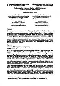
The following stages were identified and used in the simulated deployment of UAS in the experimental trials (30; as depicted in Figure 1): 1. 2. 3. 4. 5.
Launch towards Launch Complete waypoint (WP; 0-200ft AGL ascent); conventional ARFF deploys (UAS and ARFF en-route) Proceed and ascend to WPl (200-400ft AGL ascent) WPl (orbit entry; arrival on scene) - fly orbit revolutions (eight points, level flight) WP2 (orbit exit) - depart and descend to WP3 (400-200ft AGL descent) WP 3 -descend to recovery at WP 4 (200-0ft AGL descent, land)
Figure 1. Example deployment of VAS for ARFF response.
Scenarios A series of 30 unique scenarios were developed to perform the experimental trials in the application analysis framework. These scenarios contained randomly assigned variable values, some based on pre-requisite conditions or earlier dependent variable assignments. The ranges and possible options of scenario variable values were defined through data captured from National Transportation Safety Board (NTSB) narratives of fatal aircraft accidents occurring from 2011 to 2014 within five-miles of airports, national weather data (wind conditions at 30 highest traffic airports in U.S.), or associated with Salt Lake City (SLC) airport, which was selected as the common facility and environment to use in the initial experiment. The variables featured in each scenario included the range of the accident from the airport, operational phases when the accident occurred (i.e., taxi, takeoff, or landing), wind speed and direction, heading of the crashed aircraft, type of crashed aircraft (commercial, small taxi/passenger, or 20+ passenger), and origin of UAS launch (ARFF facility) .
577
UAS-ARFF Application Analysis Framework This project featured the development of an experimental application analysis framework, termed Capability Analysis and Effectiveness Response for Unmanned Systems (CAERUS). CAERUS was conceptualized and designed to support exploration and examination of any potential unmanned system configuration use, especially UAS. For this research the framework was specifically tailored to perform analysis of UAS-ARFF response, supporting loading of experimental trial details (imported parameters), implementing the theory of operation, and performing necessary calculations to determine response rate (criterion variable) of each treatment (experimental APMs and conventional ARFF control treatment). To support execution of requisite calculations a series of constants (across all experimental trials) were defined, including model attributes (APM elements) and position of the ARFF facility where the UAS was launched and recovered. The remaining details of the trial were calculated by operational stage, established for each major maneuver of the aircraft to specific waypoints in accordance with the theory of operation (launch, launch complete [ascend], WPJ [orbit entrance], WP2 [orbit exit], WP3 [descend] and WP4 [recovery]; see Figure 1). Performance calculations were carried out at each stage and treatment sequentially, taking into account possible effects of distance, altitude changes, endurance level (power remaining), and wind (speed and direction) on treatment response. Assumptions were made that environmental conditions were suitable to support UAS flight operations (i.e., acceptable visual conditions, precipitation levels, and wind not exceeding 11 kts), airspace within the operational area is free of traffic (de-conflicted), and that both conventional ARFF and experimental UAS responses were initiated (launched) concurrently. The performance results of individual APMs (experimental treatments) in each trial were calculated, resulting in a $eries of parameters that could be statistically compared through analysis. These values included indications whether the specific model exhibited sufficient endurance or range to perform the required flight plan, time required to reach the crash site, and time to complete the entire route. The time required for conventional ARFF to respond (control treatment) was calculated using a formula developed by the RAND Institute to approximate fire apparatus response time (time= .65 + [l. 7 x distance]). 12• 24 Some of the scenarios included scene conditions unnavigable to conventional ARFF using road vehicles, necessitating calculation of an additional response time when hiked (at a speed of 4.5 miles per hour [mph]), which was added to the vehicle-based response time. The total distance travelled by conventional ARFF was calculated by combining the driveable and undriveable distance values. Each scenario was subject to variation of accident distance, based on random accident scene placement, necessitating computation of a metric comparable among all scenarios and treatments. Response rate (speed) was selected for this purpose as it would vary based on model perfonnance within each scenario, but not by differing distances. The response rates for each treatment, in all scenarios, were calculated by dividing distance traveled (sm) by response time (hours). The mean response rates of the seven treatments were calculated, statistically compared, and analyzed. The findings indicated some UAS platforms would be capable of faster response than conventional ARFF (29.09 mph), specifically group 2 (46.39 mph) and 3 (62.88 mph) fixed-wing and group 3 VTOL (47.09 mph). Group 1 fixed-wing (32.44 mph) and group 2 VTOL (29.30 mph) achieved similar response speeds, while group 1 VTOL (16.23 mph) exhibited the slowest rate.
DISCUSSION The benefits of using modeling and simulation (M&S) to accurately evaluate various UAS platfonns are many, but the most obvious are savings in terms of time and money, repeatability, and the ability to vary conditions to test out multiple platfonn configurations (APMs) under varying conditions. In most general terms, a model consists of some system specification or set of
578
specifications. The most common concept of a simulation model is that it is a set of instruction, rules, equations, or constraints for generating input/output (1/0) behavior. 25 The validity of the model (also referred to as predictive validity or fidelity) depends greatly on the accuracy of the parameters used as input for model characteristics (i.e., attributes). Fidelity represents an overview term defining the extent to which the models and simulation replicate the actual environment.26·23 Inaccurate system parameters result in poor accuracy, low fidelity, and inaccurate output and validation of real-world scenarios. In the case of UAS-ARFF applications, the models consist of parameters related to specific UAS platform configurations (APMs), coupled with varying environmental and scene conditions, and used for comparison among one another and against a conventional ARFF response model to determine effectiveness. The findings supported the identification of UAS platfonns well suited to augmenting ARFF personnel in simulated emergency situations by arriving on scene faster and relaying critical infonnation. The CAERUS framework holds significant promise beyond UASARFF, and can be used for any future application in which unmanned system (UAS) employment is envisioned. As UAS become more prevalent and accepted within the National Airspace System, more uses will emerge, and the accurate selection of the most suitable platform for use in specific situations will become vital in order to maintain safety, efficiency, productivity, and effectiveness. Improving the fidelity of models is a vital factor in maintaining the utility of the CAERUS framework that has been built to date. Continuing to add UAS platforms and configurations as they emerge and refining the database of system characteristics and performance data for each will be needed to continue utilization of this analysis framework for future research, assessment, and validation of models using alternative methods. Currently, the CAERUS framework incorporates limited environmental factors, such as static ground wind effects (speed and direction) and linear route paths between waypoints (no ascent, descent, or horizontal trajectory curvature), due to preliminary constraints in development. Future iterations will feature more complex M&S, to include visibility conditions, precipitation, dynamic winds, improved route and trajectory calculations, and higher quality visual renderings. Additionally, there were individual outliers in the statistical APM source data (UAS configurations) that exhibited capabilities and perfonnance desirable in the envisioned UAS-ARFF response. These individual configurations can be identified through comparison to the following set ofrequirements generated by the research team at the conclusion of the initial testing: 1. Based on need for expedited response, an electric powered sUAS with stationary launch, requiring less than one-minute to initiate flight operations, is suggested; 2. Endurance greater than 45 minutes at a minimum cruise speed of 25 kts is suggested; 3. The sUAS should be capable of launch, operation, and recovery in winds greater than 15kts; 4. Payload capacity should exceed one-pound to accommodate carrying of an infrared sensor, color camera, dual-input video transmitter, and payload sensor gimbal to support constant tracking and transmission of visual data, while in transit and aerial orbit pattern over scene.
In consideration of the observations and findings from this research, the theory of operation was revised to incorporate a second UAS (either option A tethered VTOL or option B larger, long-endurance [group 2-3] UAS) to support sustained capture of accident scene information and perimeter maintenance. The following represent the steps of the revised theory of operation for multiple UAS-ARFF response: 1.
Perform expedited (de-conflicted) d~ployment of two UAS, concurrently with ARFF mobilization a. Ensure planned route to scene is free from conflicting air traffic b. Launch electric sUAS (with at least 45 minute endurance) c. If applicable (option B), begin preparing larger (group 2-3) UAS for launch and flight to accident scene (takes longer to prepare and launch than sUAS)
579
2.
Fly sUAS to accident scene (route to accident, capture relevant information) a. Use sUAS to establish initial sensing perimeter upon arrival at scene (sUAS enters orbit) b. Communicate information real-time to ARFF (sUAS flies orbit, captures and communicates scene information, establishes and maintains accident scene perimeter) c. Reroute as necessary to examine specific area(s ; using feedback from Incident Commander); OPTION A (Tethered VTOL UAS): 3. Upon arrival of conventional ARFF on scene, deploy tethered UAS (de-conflicted with sUAS route) 4. Once sUAS limit for sufficient fuel to RTB reached, transition from orbit to return route and recover (exit orbit, enter return route, and land) 5. Task tethered VTOL UAS to maintain perimeter and communicate information real-time to ARFF Incident Commander and reroute as necessary (replaces sUAS) 6. After desired over watch complete -OR- fuel limit reached, recover tethered VTOL UAS (end of UAS operations); OPTION B (large UAS) : 3. Launch and route large UAS to accident scene 4. Transition sUAS to RTB and recover once large UAS arrives on scene -OR- sUAS limit for sufficient fuel to RTB reached (exit orbit, enter return route, and land) 5. Task large UAS to maintain perimeter and communicate information real-time to ARFF Incident Commander and reroute as necessary (replaces sUAS) 6. After desired over watch complete -OR- limit for sufficient fuel to RTB reached , return large UAS to base; for sustained operations prepare additional large UAS within sufficient period to arrive on station as initial large UAS is ready for departure (repeat steps 3-7, as necessary) 7. Recover large UAS platform (landing and recovery; end of UAS operations).
The data and findings obtainable using the APMs and associated analyses can provide insight regarding deficient or ineffective designs, configuration considerations, or system performance, which in tum can be used to identify and isolate individual elements or components that require further research and development to improve or replace. They can also be used to exhibit positive performance or capabilities, supporting identification of new applications, strategies, or methods to safely, efficiently, and effectively employ UAS technology. These potential benefits, available using computation and analyses such as M&S, provide opportunities to better understand the limitations, constraints, performance, and applicability of specific platforms and categories prior to their acquisition and operation.
CONCLUSION Many users of UAS technology need comprehensive, real-time information in order to best understand the situations that they face during operation. The benefits of UAS, especially sUAS, are that they are relatively simple to maintain and operate, while providing an efficient and safe means of remotely gathering information. UAS have the unique capability of providing vital data such as the positions of survivors, potential evacuation routes, the location of fire risks, and site access information, which all are considered critical to response before responders even arrive on scene. Yet in order to best align platforms with missions, empirical investigation is necessary to ensure that the best possible combination thereof is identified. It is clear that, prior to the development of a UAS CONOP and the initiation of widespread flight operations, it is critical that the system limitations be fully understood and addressed. Improving awareness and understanding can be achieved through the examination of the operating environment, such as through site surveys and aerial imagery. It is also recommend that stakeholders perform detailed application analysis in the selection and configuration of UAS to be used. 4·6· 7 This study was successful in the collection and analysis of seminal data to evaluate and validate the utilization of UAS in ARFF scenanos.
580
The current study analyzed 268 unique platfonns and 282 configurations in a series of simulated responses to aircraft accidents including the deployment, flight to scene, observation of scene, site orbiting, and return for recovery. The analysis yielded specific UAS types that would be most applicable for ARFF operations, namely group 2 and 3 fixed-wing and group 3 VTOL platfonns. By providing evidence based findings, UAS and ARFF stakeholders can best recognize system limitations, performance, and applicability of platforms to best matching needs with capabilities avoiding unnecessary frustrations as well as wasted monetary and opportunity costs. Although this study establishes a significant foundation of data, additional inquiry is necessary to confirm the present findings and to expand the scope of the compatibility of mission and platform capabilities. Future research is planned to refine CAERUS to improve trajectory and maneuvers, compare additional categories or individual configurations, and evaluate UAS in varied environmental and visual conditions. The creation of new APM categories, such as electric versus internal combustion engine types, tube launched platforms, and a composite of UAS that meet outlined UAS-ARFF requirements, will be investigated. Additionally, higher quality visual renderings will be developed and expanded trials will be added at alternative locations beyond SLC airport. External validation will also be pursued using alternative methods to ensure the robustness of the findings of this study. It is envisioned that this next step will take place with actual UAS platforms. Lastly, further qualitative subject matter expert analysis and feedback will be sought to validate the outlined and expanded theory of operations. Even in light of the promising outcomes of this study, there are still some regulatory hurdles that exist that prevent immediate realization of UAS utility for ARFF. Until the final disposition and wording of the NPRM for operation and certification of sUAS is known, it is required that those individuals or organizations planning to utilize UAS pursue a COA, which has a defined review and approval process. Moreover, such requests have a high potential for success due to the numerous FAA COA approvals for related uses. 3•13. 29 Such access is necessary in order to develop a frame of best practices and provide guidance to stakeholders through UAS testing, featuring both simulation and use of actual systems, in a variety of scenarios. Practical issues such as operator training and proficiency, vehicle storage, and launch and recovery issues must be determined through actual testing. With the finalization of FAA regulations concerning sUAS operations, this type of investigation will be possible and from this further UAS utilization will become a reality. Even after the regulatory environment becomes more favorable to UAS application such as those outlined in this study, it suggested that those involved in the review, acquisition, and use of UAS periodically re-evaluate the specific technology and method of application against recent advancements and published information, such as regulatory requirements and research findings. In summary, UAS, specifically group 2 and 3 fixed-wing as well as group 3 VTOL, show significant promise to support ARFF response. With the continued thread of research outlined within this study, ARFF and UAS stakeholders will be provided with improved understanding of the appropriate platform-mission alignment, which should result in system-wide efficiencies. However, until the regulatory limitations issues are resolved, current and future research will be restricted primarily to simulation-based data collection yet with quality data such as found in this study, stakeholders will be well prepared to select the appropriate UAS for their needs and begin operations as soon as practical.
ACKNOWLEDGEMENTS This work would not have been possible without the essential input and prior work of our colleagues and research collaborators, including Dr. Ken Witcher (ERAU-W, Dean of College of Aeronautics), David Thirtyacre (ERAU-W), and Dr. Adeel Khalid. Additional recognition is due to Crew Chief Peter Gabriel (Ret., Port Authority of New York and New Jersey) for reviewing
581
and providing feedback on the initial UAS-ARFF response theory of operation used for this project and Fire Chief Duane Kann (Orlando International Airport) and Battalion Fire Chief Jason Graber (Metropolitan Washington Airports Authority) for their availability and willingness to discuss the use of UAS within ARFF incidents. A special thank you is also due to the manufacturer representatives that aided in the collection of accurate UAS platfonn configuration metrics featured in this research, including Sharon Corona (UAV Solutions, Inc.), Steve Smith (ArcturusUAV), Kevin Surrninski (MicroPilot Inc.), William Watt (MicroPilot Inc.) , Kenneth Saborio (MicroPilot Inc.), Jim Sampson (Scion UAS) Doug Challis (Challis Heliplane UA V Inc.), Tad McGeer (Aerovel Corporation), Francis Durufle (lnfotron), John Parker (lnfotron and Integrated Robotics), Juan Francisco Sainz V (IDETEC Unmanned Systems), Anton Hernandez (airelectronics), Ludwig Eberle (Airbus Defence & Space), Mauricio Ortiz (Aeromao Inc.), Dennis S. D' Annunzio (Rotomotion, LLC), Henrik Christophersen (Adaptive Flight. Inc.). Steven Gitlin (AeroVironment, Inc.), Chris Ozrnun (Draganfly Innovations Inc.), Priit Leomar (ELI Ltd), Dave Henderson (Topcon Position Systems, Inc.), Kresmir Dulic (Ascending Technologies), Simon Thompson (Aeronavics), Stephen Greene (Textron Systems), Cameron Waite (Aeryon Labs, Inc.) and representatives from Navmar Applied Sciences Corporation.
REFERENCES 1
John A. Volpe National Transportation Systems Center, Unmanned aircraft systems (UAS) service demand 20152035: Literature review and projections offuture usage (report no. DOT-VNTSC-DoD-13-0 I). Washington, DC: U. S. Department of Transportation, Research and Innovation Administration, Author, 2013. Retrieved from http:l/ntl.bts.gov/ lib/48000/48200/48226/U AS_Service_Demand.pdf 2
Unmanned aircraft systems: Perception & Potential. Washington, DC: Aerospace Industries Association, 2013 . Retrieved from http://www.aia-aerospace.org/assets/AlA_ U AS_ Report_small.pdf
3
Federal Aviation Administration, Notice ofproposed rulemaking (NPR!vf). opemrion and certification of small 1111manned aircraft systems (Docket No.: F AA-2015-0150; Notice No . 15-0 I). Washington, DC: Author, 2015. Retrieved from https://www.faa.gov/regulations_policies/rulemaking/recently_published/media/2 l 20-AJ60 _ NPRM _ 2- l 52015 joint_signature.pdf 4
M.G. Anderson, S.G. Bauer, and J.R. Hanneman, Unmanned aerial 1·ehic/e (UA V) dynamic-tracking directional 1-i:ireless antennas for low powered applications that require reliable extended range opemrions i11 rime critical scenarios (Report no. fNL/EXT-05-00883) . Idaho Falls, ID; Id aho National Laboratory, 2005. Retrieved from http ://www5 v ip. in I .gov/technical pu bl ications/docu men ts/3480252.pd f
5
E. Denney, G. Pai, C. Ippolito, and R. Lee, ··An integrated safety and systems engineering methodology for small unmanned aircraft systems." Proceedings fro111 A !AA !nforech@Aerospace 20 I:! Co11fere11ce, 2012. Retrieved from http://ti.arc.nasa.gov/ m/profi le/edenney/papers/dpil-infotech-2012.pd f
6
D. Gebre-Egziabher, and z. Xing, Analysis ofu11man11ed aerial vehicle concept ofoperatio11 i11 ITS applications (Report no. CTS 11-06). Minneapolis, MN : University of Minnesota, Center for Transportation Studies, Intelligent Transportation Systems Institute, 2011. Retrieved from http://www.cts.umn .edu/Publications/ResearchReports/pdfdownload.pl?id= l 512
7
0. Ison, B. Terwilliger, D. Vincenzi, and T. Smith, Unmanned aerial system use in airport rescue and fire fighting(# 1078). Paper presented at the 2015 Aviation I Aeronautics I Aerospace International Research (A3 IR) conference, Phoenix, AZ, 2015. 8
S.R. Perry, and J.H. Taylor, A prototype GU/for unmanned air vehicle mission planning and execution. Paper presented at the 19th World Congress, the International Federation of Automatic Control, Cape Town, SA, 2014.
9
8. Terwilliger, D. Vincenzi, D. Ison, K. Witcher, 0 . Thirtyacre. and A. Khalid, .. Influencing factors for use of unmanned aerial systems in support of aviation accident and emergency response." Journal of Automation and Control Engineering, 3(3 ), 2015, 246-252. doi : I 0.12720/joace.3 .3.246-252 10
P.P Wu, and R. A. Clothier, "The development of ground impact models for the analysis of the risks associated with Unmanned Aircraft Operations over inhabited areas.'' Proceedings of the I I th Probabilistic Safety Assessment and Managem ent Conference (PSAM 11) and the Annual European Safety and Reliability Conference (ESREL 2012), Scandic Marina Congress Center, Helsinki, 20 I 2. Retrieved from http://eprints.qut.edu.au/53082/ l /Wu_ and_Clothier.pdf
582
11
B. Terwilliger, 0 . Vincenzi, and 0. Ison, "Unmanned aerial systems: Collaborative innovation to support emergency response. " Jou ma I of Unmanned Vehicle Systems, 2015. doi: I 0.1139/juvs-2015-0004 12
0. Vincenzi, 0. Ison, and B. Terwilliger, ·'The role of unmanned aircraft systems (UAS) in disaster response and recovery efforts: Historical. current. and future. " In Proceedings of the Association for Unmanned Vehicle Systems International 4 !' 1 Annual Symposium, Orlando, FL, 2014. 13
Federal Aviation Administration, Unmanned aircraft systems (UAS) frequently asked questions, 20 I 5. Retrieved from https ://www.faa.gov/ uas/ faq/ 14
Federal Aviation Administration, Petitioning for exemption under Section 333, 2015. Retrieved from https://www.faa.gov/uas/legislati ve_programs/section _333/how_to _file_ a_petition/ 15
Federal Aviation Administration, FAA streamlines UAS COAs for section 333, 20 I 5, para. 3. Retrieved from http ://www.faa.gov/news/updates/?newsld=82245&omniRss=news _ updatesAoc&cid= I 01 _N _ U 16 0. Geister, and M. Suijkerbuijk, The mature unmanned aircraft ground control station (MUAGCS). Paper presented at the 7th International UAV World Conference, AirTec - UAV World Conference, Frankfurt, GE, 2012. Retrieved from http://www .researchgate.net/profile/ Dagi_ Geister/publication/23 3782264_The_ Mature_Unmanned_Aircraft_ Ground_ Contra I_ Station _(MU AGCS )/links/09e4150b 74cbe9ddf2000000.pdf 17
Y. A Iver. M. Ozdogan, and E. Yucesan. " Assessing the robustness ofUAV assignments." Proceedings of the 2012 Winter Simulation Conference (WSC), 2012, pp. 2378-2388 . doi: I 0.1109/WSC.2012.6465009
18
U.S . House Committee on Oversight and Government Reform, Testimony of Dyke D. Weatherington, Deputy Director, Unmanned Wa1fare, Office of the Under Secretwy of Defense (Acquisition, Technology & Logistics) before the United States House Committee on Oversight and Government Reform, Subcommittee on National Security and Foreign Affairs, 20 I 0. Retrieved from http://fas.org/irp/congress/20 IO_hr/03231 Oweatherington.pdf 19
U .S. Department of Transportation, Memorandum, Audit announcement - Review of FA A 's oversight a/Aircraft Rescue and Fire Fighting Program. Washington, DC: Author, 2014. Retrieved from h ttps: //www. o ig.dot. gov Is ites/ defau It/fi les/F A A%20 A ircraft%2 0 Rescue%20 and %20 F ire%20 F igh ting%20 Pro gram %2 0 Announcement%20Letter%5 EAugust%206,%202014.pdf 20
1. Kreckie, "Aircraft Rescue and Fire Fighting (ARFF) ." In A. Cote (Ed.), Fire Protection Handbook, pp. 13-99-13115. Quincy, MA: National Fire Protection Association, 2008 .
21
CBS Baltimore. " 2 Injured after small plane crash near Tipton Airport," February 8, 2015 . Retrieved from http :/Iba! timore.cbs local. corn/2015/02/08/smal 1-p Iane-crash-reported-near-tipton-airport/
22
ISO, Response-time considerations. Retrieved from https ://firechief. iso. com/ FCWW eb/mitigation/ppc/3000/ppc3015 .j sp
23
P. Kolesar, P. A Mode/for Predicting Average Fire Company Tra vel Times . New York, NY: RAND Institute, 1975.
24
P. Kolesar, and E.H. Blum, Square Root La ws for Fire Engin e Response Distances. New York, NY: RAND Institute, 1973.
25
8 . Zeigler, H. Praehofer, and T . Kim, Theory of Modeling and Simulation: Integrating Discrete Event and Continuous Complex Dynamic Systems (2ed) . Waltham, MA: Academic Press, 2000. 26
S.M . Alessi , " Fidelity in the design of instructional simulations," J. Comp.-Based Instruction , 15(2), 1988 , pp. 40-4 7.
27
D.C. Gross and R. Freeman, R., Measuring fidelity differentials in HLA simulations. Presented at Fall I 997 Simulation Interoperability Workshop, Orlando , FL.
28
D. Liu, N. Machiarella, and D. Vincenzi, .. Simulation fidelity. " In D. Vincenzi, J. Wise, M. Mouloua, and P. Hancock (Eds.), Human Factors in Simulation and Training. Boca Raton, FL. CRC Press, 2009 . 29
Federal Aviation Administration, Freedom of Information Act responses, 20 l 5. Retrieved from https ://www .faa .gov/uas/public_ operations/foia _responses/
583