Distributed processing systems (DPS) find many applications in various ... system with the focus on multiple-UAV cooperative teams realizing a single ..... Chmaj G., Latifi S.: Decentralization of A Multi Data Source Distributed Processing System. Using A Distributed Hash Table, International Journal of Communications, ...
Author's copy
UAV cooperative data processing using distributed computing platform Grzegorz Chmaj, Henry Selvaraj
Abstract – Unmanned Aerial Vehicles (UAV) are being increasingly used in growing number of applications. The use of single vehicle is often not enough due to various limitations, such as available power or sensors installed. Therefore the UAVs are formed into cooperative teams that operate as the distributed processing system realizing the given mission with one or more objectives (tasks) defined. The key factor for such unmanned aerial vehicles teams is the energy efficiency – as each UAV is limited with either battery power or the amount of combustible fuel. In this paper we address this problem and propose the design of UAV-based distributed processing system for which we optimize the OPEX (operational expenditure). We propose the principles of the system, its key elements in a form of mathematical description, and show how it can be used for a collaborative team of unmanned aerial vehicles realizing the object detection mission. Keywords: UAV, unmanned aerial vehicles, drones, distributed processing, energy efficiency
1
Introduction
Distributed processing systems (DPS) find many applications in various systems of different scale. In this paper we present a general structure for a distributed processing system with the focus on multiple-UAV cooperative teams realizing a single mission. The contribution of this paper is the novel concept of distributed processing system in which the management is moved to the nodes that can perform various roles simultaneously. We also present the system design details, including the definition of the task, DSD (Distributed System Data) idea, the energy consumption model and experimentation results that show the value of proposed ideas.
2
Literature overview
The distributed processing systems find many applications on various architectures. Authors of [1] presented the way to model the multiscale distributed computing, using the MML (Multiscale Modeling Language). The presented method is later used for nanotechnology and biophysics applications. One of important aspects for distributed processing is the resource discovery – centralized systems are easy to implement, but introduce the single point of error and can face the bottleneck problems. [2] contains the
classification of decentralized resource discovery mechanisms, also in our previous work [3] we presented the use of DHT (Distributed Hash Table) as the resource localization mechanism for the distributed system having nodes equipped with multiple data sources. The efficiency of distributed processing system is often measured by the electrical energy consumption – same way as we model the efficiency in this paper. In [4] the energy evaluation of multi-processor system is presented, along with the experiments comparing two approaches of realizing the multi-processor computations. The specific computational needs can be addressed using the specialized techniques such as CUDA [5], this way increasing the efficiency of the system. For the UAV-based distributed processing system presented in this paper we use the object detection mission as the example. However these kind of UAV teams can realize various other applications, such as area surveillance, object tracking, fire detection etc. [6].
3
System description
The goal of this paper is to present a model of distributed processing operation using UAVs equipped with multiple data sources (such as cameras, radars, etc.). We use the general paradigm of distributed processing system and propose an architecture that is also applicable to other platforms (UGVs, combination of UAVs and UGVs, and systems incorporating elements of other types). Unmanned Aerial Vehicles (interchangeably called nodes in this paper, according to the terminology used for distributed processing systems) communicate using the common overlay network, to which the interface is defined. The transmission level and all the abstraction behind the overlay network is out of the scope of this paper. The nature of distributed processing includes the task division into fragments that are further sent for processing to selected nodes. The results are collected at the designated node, and then combined into the final result. 3.1
Architecture overview
Distributed processing systems usually are managed using some designated units, often the management is centralized and performed by a single element specialized into that role. This element performs the task management. In this paper we propose another approach: we let every node propose its task. This way each node can manage its own task, communicate with other nodes as the task manager and collect the results. DIAPS (DIstributed Aerial Processing System) contains V UAV denoted as: v = 1, 2, …, V (1). Each of them can possess multiple properties and can perform various roles. We propose flexible roles management in which roles are not strictly assigned to UAV nodes, like it is implemented in most UAS (Unmanned Aerial Systems) and DPS. In our approach, there are R roles defined denoted as r = 1, 2, …, R (2) and each node must have at least one role assigned and is not limited to their maximum number (3), (4). qv,r = 1 if role r is present on node v, 0 otherwise 𝑅
∑
𝑞𝑣,𝑟 > 0
𝑟=1
v=1, 2,…,V
(3) (4)
In this paper, we consider three basic roles defined for the processing system: control node (CN) – node holding this role is supplying the system with the management services, such as asset localization. task manager (TM) – this role is played by a node that registered the task to the CN computation (CP) – the node is processing blocks, either received from other nodes (task owners) or those who are part of its own task As mentioned earlier, nodes can register the task in the system and play the role of task manager. Thus there are Z tasks processed in the system z = 1, 2, …, Z (5), each divided into a given number of blocks b = 1, 2, …, Bz (6). Blocks’ affiliation is denoted by variable xbz (7): xbz= 1 if block b belongs to task z; 0 otherwise.
(7)
Each UAV node holds some computation power provided by processing units (PU) denoted as p = 1, 2, …, P, also a vehicle has G hardware sockets installed (8) denoted as g = 1, 2, …, G. Each pu has the type defined and is installed in one of vehicle’s sockets (9). Each socket must be equipped with processing unit (10). wv,g = 1 if socket g is installed on node v; 0 otherwise. up,g = 1 if processing unit p is installed in socket g, 0 otherwise 𝑃
∑ 𝑝=1
𝐺
∑ 𝑔=1
𝐺
𝑤𝑣,𝑔 𝑢𝑝,𝑔 = ∑
𝑔=1
𝑤𝑣,𝑔
𝑣 = 1, 2, … 𝑉
(8) (9) (10)
Unmanned Aerial Vehicles gather data from their surroundings and environment using data sources (DS) denoted as d = 1, 2, …, D (thus there are D data sources in total present in the described system). Often times UAV’s data sources are called sensors, however in our work we use only data source, to avoid the confusion with other systems, such as sensor networks. Each vehicle has ∑𝐷 𝑑=1 𝑘𝑣,𝑑 data sources installed, however its number can be zero as well (11, 12). kv,d = 1 if datasource d is present on node v; 0 otherwise 𝐷
∑ 𝑑=1
3.2
𝑘𝑣,𝑑 ≥ 0
𝑣 = 1,2, … , 𝑉
(11) (12)
Task definition
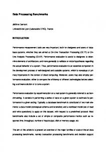
The proposed UAV-based distributed processing system is designed to perform mission of various kinds. The objectives of the missions and all related and required data is defined in the task object whose internal structure is proposed as follows: Task is the structure that contains the following elements (Fig. 1):
task raw data – binary/ASCII data that is to be processed during the mission defined blocks – blocks that are defined by the task designer online blocks – definitions of the online blocks
Fig. 1. The structure of the task
Blocks are the fragments of the task that can be separately processed on designated vehicle. We distinguish three types of blocks, denoted as, bt2, bt3: block offline – the type of block that is created as the division of task raw data (bt1 = 1) block defined – the type of block, for which all parameters are specified manually by the task designer (bt2 = 1) block online – blocks that are processed in a loop until the task processing is finally finished (bt3 = 1). Blocks offline and blocks defined are processed in order to produce one-time result. They might be requested to be processed again as well, but such a request must be placed by task manager. Blocks online are processed repeatedly (thus they are also defined this way) during the task (mission) operation and are able to constantly provide the result of their processing. Each block must have the type assigned (13). ∑
𝐵𝑧
𝑏=1
(𝑏𝑡1 + 𝑏𝑡2 + 𝑏𝑡3 ) = 𝐵𝑧
(13)
Block has the internal structure defined, that contain the combination of data, data sources and functions. Data is assigned either at the stage of task raw data division using task_divide() function (for blocks offline) or manually by the task designer (for blocks defined and blocks online). Data sources specify which data source up-to-date values are required for block processing, given block may require any number of data source values, but also can be defined without such requirement (14, 15). For blocks offline, the task_divide() function defines these data sources and each block offline holds the same requirement. Blocks online and blocks defined are specified manually, thus the data sources assignment can be different for each block. Functions identify which functions are used to process the particular block, and there are F functions known to the system, denoted as f = 1, 2, …, F. Similarly to data sources, task_divide() function assigns functions for blocks offline, and blocks online and blocks defined are
set up individually. Each block must have at least one processing function assigned (16, 17). lb,d = 1 if block b requires data source d; 0 otherwise
(14)
𝐷
∑ 𝑑=1
𝑙𝑏,𝑑 ≥ 0
𝑏 = 1,2, … , 𝐵𝑧
nb,f = 1 if block b requires function f; 0 otherwise
(15) (16)
𝐹
∑
𝑛𝑏,𝑓 > 0
𝑓=1
3.3
𝑏 = 1,2, … , 𝐵𝑧
(17)
Implementation of functions and Processing of blocks
As stated by (16) and (17), block contains the identifier(s) of functions that need to be run for the block in order to obtain the result (19). The identifiers are not the actual functions though. A node must know the function implementation – i.e. the binary implementation i of the function f must be present locally on the vehicle v (21). Functions implementations are denoted as i = 1, 2, …, F. This requirement raises the problem of blocks to nodes assignment – blocks have different functions requirements (20) and UAVs possess different functions implementations (18). This problem is solved by separate algorithm TM_BA run by task manager. hv,f = 1 if function f is implemented on node v; 0 otherwise yv,b = 1 if block b is processed on node v; 0 otherwise nb,f = 1 if block b requires function f; 0 otherwise 𝐹
∑ 𝑓=1
∑
𝐵𝑧
𝑏=1
ℎ𝑣,𝑓 𝑦𝑣,𝑏 = ∑
𝐵𝑧
𝑦𝑣,𝑏
(18) (19) (20) (21)
𝑏=1
The matrices of qv,r, wv,g, lb,d, nb,f and hv,f constitute the distributed system data (DSD), that is the base for the system operation. Task raw data is the terrain data that is divided into the regions, processed in distributed manner by multiple UAVs in a team. The location of presented matrices depend on the roles: qv,r is stored at CN vehicle, wv,g, lb,d and nb,f are stored at TM node. The knowledge state also depend on the function: wv,g matrix is constant during the mission, so it can be uploaded to CN before mission start (if CN is determined) otherwise CN will obtain this data from other UAVs. Matrix qv,r is constant if the assignment of CN roles is constant, if CN roles are assigned dynamically, then this matrix will be dynamically updated as well. Matrices lb,d and nb,f are stored only at TM node, that manages related task. 3.4
Energy emission model
The presented algorithms and DIAPS design focus on the efficiency of operation which is expressed as the electrical energy consumption. We choose this metric, as it is the essential factor for UAV based distributed processing systems, because the energy available at each vehicle is limited (either for battery powered units or the ones using
combustion engines). The additional motivation is that electrical energy consumption is the base for many other system parameters, such as processing speed, team range of operation, time of operation and many others that are dependent on electrical energy efficiency. The model defines multiple elements of energy usage: 1,𝑝,𝑓 𝑒𝑣 = const – the energy required to process 1kB of data in offline/defined block using function f at PU p installed on node v (size-related) 2,𝑝,𝑓 𝑒𝑣 = const – the energy required to process offline/defined block at PU p installed on node v using function f (size-unrelated) 3,𝑝,𝑓 𝑒𝑏 = const – the energy required to process block online for time period (slot) t 𝑒 4 = const – the energy required to send 1kB of data between two UAVs 𝑠𝑏1 = size of data enclosed in block b 2 𝑠𝑚 = size of the message m av,b = 1 if block b is processed on node v; 0 otherwise. t = 1, 2,…, T – time period (slot) of the defined length. This index is used for the modeling and the length of t determines the accuracy of OPEX modeling. In this paper we assume the t being the length of 1 second. jv,b,t = 1if online block b is run on the node v at the time slot t; 0 otherwise. yb,p = 1 if block b is processed at socket p; 0 otherwise. c – node index: c = 1, 2, …, V m – message index: m = 1, 2, …, M km,v,c = 1 if message m is being transmitted from node v to node c The total OPEX (operational expenditure) is: 𝑉
𝑂𝑃𝐸𝑋 = ∑ 𝑣=1
3.5
𝐵𝑧
∑
𝑏=1
𝐹
∑
𝑃
∑
𝑊
∑
𝐺
∑
𝑇
∑
(𝑦𝑏,𝑝 𝑤𝑣,𝑔 𝑠𝑏
𝑓=1 𝑝=1 𝑤=1 𝑔=1 𝑡=1 2,𝑝,𝑓 3,𝑝,𝑓 + 𝑎𝑣 𝑒𝑣 𝑦𝑏,𝑝 𝑤𝑣,𝑔 + 𝑡𝑗𝑣,𝑏,𝑡 𝑦𝑏,𝑝 𝑤𝑣,𝑔 𝑒𝑏 ) 𝑇 𝑀 𝑉 𝑉 2 +∑ ∑ ∑ ∑ 𝑘𝑚,𝑣,𝑐,𝑡 𝑒 4 𝑠𝑚 𝑡=1 𝑚=1 𝑣=1 𝑐=1
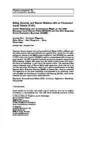
System operation
DIAPS uses several internal algorithms at the various logical areas of the system. Fig. 2. presents the top-level operational algorithm of the DIAPS, with the logical areas pointed out. Team level shows the behavior of the UAV-based distributed system from the mission point of view. Task manager includes the actions taken by the vehicle that implements the TM role, and computation node area shows actions executed by CP node. Depending on the DIAPS configuration, TM node can also implement CP role, or they can be placed on separate nodes.
Establish the UAV team (including CNs)
Prepare task task_divide()
Start task (start mission)
Register task in the team (at the CN node)
Match block to requestor, send block
Request blocks from task manager UAV (if PU available)
received block:
N
bt1 + bt2 > 0 ?
Run the function defined in block
Y
Get data sources values Process block using specified functions Send the result to task manager
computation node Receive result, use /combine into grand result
End mission?
Y Stop online blocks Mission stopped
Unregister task (at CN)
team level
task manager node
Fig. 2. The algorithm diagram for DIAPS
The diagram shows operations for various roles, roles can be executed concurrently (the whole system runs as full parallel architecture) – therefore some simplifications had to be done in order to show the DIAPS operation as a whole. The main internal algorithms are: TM_BA – run within TM role, selects the block to be sent as the response to block request message (sent by computation node within CP role). TM_BA requires the requestor’s processing and DS capabilities enclosed in the block request message. AN_CN – the automatic assignment of the CN role. This algorithm specifies the criteria that a node must meet in order to take CN role. This algorithm is executed periodically at each node, however the mission designer can set such criteria that only one UAV will hold the CN role during the whole mission. CP_DS – algorithm used to obtain the DS values needed for the block’s computation. It must be implemented, as various vehicles can be equipped with same data sources, and CP node must select the most convenient one. CP_PU – algorithm that assigns the block to the available PU. This algorithm works at the stage of block requisition – given PU node sends the specific information in the block request message, according to resources available locally at that time. In the work presented hereby, we describe the general functionalities of the main internal algorithms, however their details are out of the scope of this paper.
4
Experimentations
Based on the architecture proposed in previous sections we performed a series of experiments in which we use the following application of UAV-based distributed processing system to realize the object detection mission. The diagram of the simulated DIAPS is shown in Fig. F4, and table 1 contains system elements with values.
Fig. 3. The schematic of DIAPS for object location mission Table 1. Elements of DIAPS Nodes:
V=6
Blocks:
b = 1, 2, …, B1 𝑠𝑖𝑧𝑒(1)
B1 = 6 + ⌈ 1 ∑𝐵𝑏=1 𝑏𝑡1 𝐵1 ∑𝑏=1 𝑏𝑡2 1 ∑𝐵𝑏=1 𝑏𝑡3
Data sources: Tasks:
qv,r matrix: r 1 2 3 1 1 1 1 2 0 0 0 3 0 0 1
𝑠𝑏1
Processing units: Functions:
P=G=8 up,g = 1 p = g = 1…8 F=4 {image filtering – camera picture, image filtering – IR image, radar signal processing, GPS signal interpretation}
Roles:
R=3 {CP, CN, TM}
⌉
= 𝐵1 – 4 =2 =2
D=6
∑𝐷 𝑑=1 𝑘𝑣,𝑑 = 1
v = 1…8
Z=1
4 1 0 0
5 1 0 0
6