int. j. prod. res., 1 september 2004, vol. 42, no. 17, 3743–3763
UL-PML: constraint-enabled distributed product data model Y. WANG and B. O. NNAJI* The global economy has made manufacturing industry more distributed than ever before. Product design requires more involvement from various technical disciplines at different locations. In such a geographically and temporally distributed environment, efficient and effective collaboration on design is vital to maintain product quality and organizational competency. Current standard computeraided design data formats do not support design collaboration effectively in terms of design information and knowledge capturing, exchange, and integration. Design constraints cannot be represented and transferred among different groups, and design information cannot be integrated efficiently within a distributed environment. A new design data model, the Universal Linkage model, is developed here to represent design-related information for network-based collaborative design. It incorporates geometric and non-geometric constraints with traditional geometric elements, thus allowing more design knowledge sharing in collaborative design. Segments of design information can be linked and integrated into a set of complete product data. Thus, lean information exchange can be realized. This model, which has good properties of openness and extensibility, is represented by Directed Hyper Graph and Product Markup Language.
1. Introduction Global market calls for collaborative design among designers, manufacturers, suppliers and vendors. The business pressures toward outsourcing let much of the design work of complex products be done across firms. Ford estimates there are up to 800 links of supplier relations, and automotive companies are substantively relying on these suppliers to participate in vehicle design (NSF e-Design Workshop 2000). The Defense Advanced Research Projects Agency (DARPA) estimates that the supply chain accounts for more than 50% of weapon system and major subsystem production costs (Parunak 1997). In such a geographically and temporally distributed environment, efficient and effective design collaboration should be assured to maintain product quality and organizational competency. Advanced collaborative design tools and technologies are needed so that stakeholders such as customers, suppliers, government agencies, retailers and others can participate in product development at the early stages so as to reduce the risk of failure and shorten the design cycle. There are new issues on information modelling and communication in collaborative design. First, collaborative design over networks requires a common and easy-to-use standard for design information representation. To ensure effective information transferring, design data exchange protocols should be established by Revision received November 2003. NSF I/UCRC Center for e-Design, University of Pittsburgh, 1048 Benedum Hall, Pittsburgh, PA 15261, USA. *To whom correspondence should be addressed. e-mail:
[email protected] International Journal of Production Research ISSN 0020–7543 print/ISSN 1366–588X online # 2004 Taylor & Francis Ltd http://www.tandf.co.uk/journals DOI: 10.1080/002075403410001708443
3744
Y. Wang and B. O. Nnaji
the computer-aided design (CAD) industry to support different CAD systems. Current neutral formats only capture static geometric information and part of administrative information. Other information that contains modelling history and design intent such as parameters, features, constraints and other dynamic relations is lost due to translation. To exchange all useful information about a product, a more powerful data format should be developed to integrate various design information. Second, the information infrastructure that supports Internet-based product development should be established to assist the cooperation among various design and analysis systems. Current CAD data formats were designed for stand-alone systems. All the information about components and assemblies has to be available locally in order to be processed. Transferring CAD information among design collaborators requires a large amount of data to be moved around, which is inefficient with current limitations of the communication bandwidth. Furthermore, corporations do not wish to expose complete design data to customers or suppliers because of information confidentiality. Secure communication among collaborators should be established based on users’ need to know and their affiliated organization. Current CAD files lack flexibility on selective design information retrieving and reuse. They do not support partial data queries. If only a fraction of design data is needed, information cannot be retrieved without querying the whole file. A collaborative design data model should support lean information processing. It should be compliant with industry standards of programming, communication, networking, system management, and interfaces between applications and system services. It should also have good compatibility and interoperability with current design and engineering systems. The paper presents a new scheme, UL-PML, for CAD information modelling within the context of Internet-based services and transactions. To maximize the openness, flexibility, scalability and integrity of collaborative design, this data scheme intends to be portable across different Internet protocols, network configurations and operating systems. This data scheme has a distributed style that supports the required scalability and extensibility of collaborative design systems. A Universal Linkage (UL) model is developed to capture geometric and nongeometric entities and relations. The model also allows design information elements to be linked over the Internet so that geographically distributed design partners can build a logically integrated product model. Graphically, Directed Hyper Graph (DHG) symbolizes the UL model. Computationally, Product Markup Language (PML) (Wang and Nnaji 2001, Wang et al. 2003) represents this model. PML has the syntax of eXtensible Markup Language (XML) (WWW Consortium), which is an emerging Internet information transferring standard. Section 2 reviews different design data models and the special requirements for network-oriented CAD data models. Section 3 presents the UL model and DHG representation. Section 4 describes the basic syntax and semantics of PML. The schemas of PML in the context of mechanical design are also defined. Representation of geometric and non-geometric constraints is discussed in section 5. 2.
Background There are two types of relations among geometric entities to be modelled. One is a static relation that exhibits the basic structural or topological information of entities, such as the aggregation relation between a line and its two end points. Another is a dynamic relation that is added by the designer as a constraint, such as the distance
UL-PML: constraint-enabled distributed product data model
3745
between two points or the concentricity of two holes. The dynamic relations can be changed without altering the structural information of geometric elements. The mechanical design needs to capture both static and dynamic aspects. 2.1. Challenges of CAD data modelling in collaborative design Current neutral CAD models (e.g. IGES and STEP) are similar to some general information models such as ER (Elmasri and Navathe 1994), IDEF1X (Kusiak et al. 1997) and NIAM (Verheijen and Van Bekkum 1982), which emphasize structural and static relationship of entities. Variant relations among geometric entities such as parameters and constraints cannot be represented. There are some research efforts to include parametric information into STEP. Examples are the programme of Enabling Next GENeration mechanical design (ENGEN) (Shih and Anderson 1997) sponsored by DARPA and PDES, Inc., and the work of the National Institute of Standards and Technology (NIST) Parametric Group (Pratt 1996, 2001). Though certain form features and geometric constraints are modelled in the above research, these representation methods are not generic enough to consider both geometric and non-geometric constraints and to support both implicit and explicit modelling. Design knowledge and constraints consist of both geometric and non-geometric aspects. Generally, there are four kinds of approaches to solve geometric constraints in parametric systems: numerical, artificial intelligence, symbolic and constructive. A unified constraint representation form is needed to support different kinds of internal representations. Since non-geometric constraints cannot be represented in current geometric modelling systems, designers need to interpret most of the non-geometric constraints into geometric ones. However, there are large amounts of non-geometric constraints that cannot be interpreted and integrated into geometry. It is critical to capture non-geometric constraints explicitly in the design data to retain the source of geometric interpretation and prevent misconception and information loss. To capture specification and design intent, multidisciplinary engineering constraints should be incorporated into CAD data. To allow design collaborators to understand the design and be able to view, edit, analyse and exchange models effectively, parametric construction and the corresponding transition from implicit to explicit models should be included in an integrated product model to enhance interoperability. Furthermore, a system-independent data format is vital to ensure the openness of information exchange within a distributed design and engineering environment. It will be advantageous that this ideal format is network-oriented at the implementation level, i.e. compatible to the Internet protocols and open standards. At the semantic level, this format should be object-oriented, which extensively supports data abstraction in a well-developed style. With the emergence of XML, the data exchange over the Internet can have a uniform format. 2.2. Application of XML in CAD data modelling XML has the characteristics of being simple, extensible, portable, interoperable and object-oriented. Some research applied XML in CAD/computer-aided manufacturing area for meta-design information capturing and exchange. Ratchev et al. (2000) developed a decision-making environment for distributed product and facility prototyping in an extended enterprise. XML is used for conveying design and manufacture messages across traditional technology boundaries. Kahn et al. (2001) are
3746
Y. Wang and B. O. Nnaji
working on a framework for transforming EXPRESS into XML and viewing with standard World Wide Web browsers. Burkett (2001) proposes a mapping between EXPRESS and XML Data Type Definition (DTD). NIST’s Design Repository project (Szykman et al. 1999, 2000) created XML mappings for function and flow in order to support representation of artefact function models in software systems. However, the above research represents geometry based on existing neutral formats (STEP or VRML). Dynamic relations among geometric entities that represent a large mount of design knowledge are not considered. 2.3. Requirements for design information representation in collaborative design How to build good design information models to meet the requirements of mechanical design is important. Spooner (1991) has a list of requirements for object-oriented CAD data models. Data must be modelled as objects organized into aggregation and generalization hierarchies. The data model must allow definition of operations (methods) for objects, the intentions and extensions of objects, and dynamic schemas. It must support the inheritance of properties and operations, strong typing, and recursive object structure. It should also have efficient and flexible capabilities for object update and multiple inheritance. It should provide support for procedure, specification and enforcement of data integrity constraints. Eastman and Fereshetian (1994) propose criteria to evaluate product models in CAD/computer-aided manufacturing development. A good model should provide full abstract data types that include object behaviour, multiple specialization, composite object and relation within composition. It must have the ability to model relations on object structure, relations between variables, and variant relations for schema evolution and the state of integrity. The model should also support integrity management of external applications, management of partial integrity for iterative design, and schema evolution for design evolution and refinement. From the viewpoint of interoperability, the ideal representation model for collaborative design should have the following properties. It is declarative in nature and self-explanatory. It should be able to capture the inherent properties and relations among objects explicitly. Those relations include functional, structural and performance aspects, as well as parametric, spatial and other constraints. Properties and relations should maintain good persistency during information exchange and design evolution. The model should be semantically comprehensive. The engineering meaning of design can be clearly uttered. The model should be both modularly selfcontained and flexible so that various objects and their relations can be captured, stored and queried in an arbitrary manner. Additionally, the representation should be extensible. When new entities and relations are needed, it should be able to be extended. At last, to encourage openness, this model should also be simple enough and comprehensible to both humans and machines. An open model needs to represent product data and design constraints effectively and thoroughly so that all relevant product information can be carried and exchanged seamlessly. The UL-PML scheme hence is developed for this purpose to overcome the shortcomings of the existing models. 3.
Universal Linkage (UL) model Three fundamental questions should be answered to build a design information structure. (1) What kinds of information elements are to be captured? (2) How would these elements be represented? (3) How can information be retrieved from these
UL-PML: constraint-enabled distributed product data model
3747
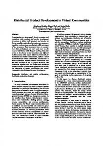
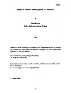
elements? These questions deal with information abstraction, representation and deduction. 3.1. Information elements of the UL model Similar to other information models, the UL model has the fundamental elements of entities and relations. An entity is an object that exists as a distinguishable unit in the universe of discourse of design. It should possess unique attributes and be an abstract image of any real object. It is the associated attributes that identify or modify an entity. A relation captures the logical or natural association between two or more entities. Relations are categorized into two types: static and dynamic. A static relation indicates the essential and inherent affiliation of entities in order to form a physical object. Static relations form the basic structure of a part or assembly, which represent inherent geometric and topological affiliations. Static relations include aggregation, which transforms a relationship between objects into a higher-level object; generalization, which refers to an abstraction in which a set of similar objects is regarded as a generic object; and other general association. In CAD information models, geometry-related relations mostly are aggregations while non-geometric (e.g. administration, material) relations include both that of aggregations and generalizations. Generalization is mostly used in the meta level of model definition. Dynamic relation specifies the extrinsic affiliation among entities that indicates additional connection or preference, such as dependency, limitation, or restriction. It is specified operationally by designer. Unlike the ER-type models, which only capture static relations, the UL model differentiates static and dynamic relations because dynamic relations are crucial for constraint representation. 3.2. Directed Hyper Graph (DHG) Graphically, UL model can be represented by DHG, in which a node denotes an entity and an arc stands for a relation. A geometric entity is represented by an elliptical node in DHG, while a non-geometric entity is represented by a rectangular node (figure 1). Arcs with solid line in DHG represent static relations (figure 2). Arcs with dash line denote dynamic relations or constraints. A constraint relation is identified by a constraint entity, which can be either geometric or non-geometric. The definitions of entities and relations should satisfy the following requirements: all types of relations are antireflexive. Aggregation and generalization have transitive properties. The direction of an arc implies a specific asymmetric unitary meaning of the relation. A constraint entity is associated with one, two or more entities.
Figure 1.
POINT
EDGE
CURVE
MATERIAL
SURFACE
MTTF
(a) geometric entities
(b) non-geometric entities
Examples of geometric and non-geometric entities in Directed Hyper Graph.
3748
Y. Wang and B. O. Nnaji Aggregation Geometric constraint Generalization Non-geometric constraint Association (b) dynamic relations
(a) static relations
Figure 2.
Static relations and dynamic relations in Directed Hyper Graph. p2 t2 l2
l1
d1 t1
t0
l0
p0
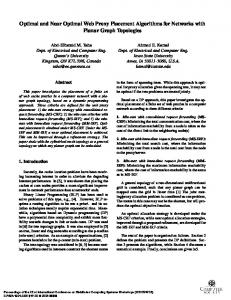
Figure 3.
p1
d0
Triangle with dimensional constraints.
SHELL: s0
BODY:b 0 conDISTANCE:d1
WIRE:w 0 conDISTANCE:d0
LINE:l 0 EDGE:e 0
EDGE:e 1
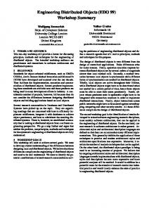
Figure 4.
VERTEX:v 1
LINE:l 2
EDGE:e 2 POINT:p0
VERTEX:v 0
LINE:l 1
VERTEX:v 2
POINT:p1 VECTOR:v0
POINT:p2 VECTOR:v1
VECTOR:v2
Directed Hyper Graph representation of the triangle in figure 3.
Figure 3 shows a two-dimensional triangle with dimensional constraints. Its geometric and topological information as well as constraints can be modelled in DHG (figure 4).
3.3. UL among entities To enable the seamless composition of a product from different groups, a new modelling technique is needed to support the integration of distributed design information. Besides differentiating the static and dynamic relations among entities, another key feature of the UL model is that relations among entities are not restricted within one data file. The relations of entities located in different files and domains can also be created. Relations are linkages among information elements. A linkage model allows physically distributed entities to be linked, thus a logically integrated set of design information can be built. As shown in figure 5, relations of entities (both static and dynamic) in different domains and physical locations can
UL-PML: constraint-enabled distributed product data model
3749
INTERNET
Figure 5.
Universal linkage between files.
Figure 6.
Point in Product Markup Language.
be created. One can easily refer entities in other data files, either at the same machine or at other locations over the Internet. Graphically, UL model can be illustrated by DHG. Textually, a UL model is represented in PML and processed by computer systems. Section 4 describes the syntax and semantics of PML. 4. Syntax and semantics of Product Markup Language (PML) XML is emerging as the data representation standard for web services. PML is designed to be totally compatible with XML standards. 4.1. Syntax of PML XML provides a common syntax for data modelling. It offers a user-defined and extensible format to represent data and information for different application areas. The syntax of PML strictly follows that of XML to ensure usability and interoperability. The compliance to industrial computation and communication standard is the premise of computational interoperability at the machine level. The syntax of XML is specified at the World Wide Web consortium (W3C XML). Figure 6 shows a simple example of point modelled in PML following the syntax of XML. Tag set and specifies the geometric meaning of symbol point1 and its attributes of x, y and z. 4.2. Schema of PML To enable an XML-style language to be used in a particular area, additional efforts should be made to define the semantics of that language. Specifying the tags used in PML is one of the major tasks in defining PML. This includes what kinds of elements to be used to model geometric and non-geometric entities, what types of attributes to be specified for each entity, and how to capture the relations among entities. There are two ways to specify the structure of instance documents and the data type of each element and attribute in XML: Data Type Definition (DTD) and Schema. Some disadvantages of DTD make people turn to Schema. DTD has a different syntax from XML. Two processing systems are needed to process XML and DTD separately. Furthermore, DTD supports a limited capability for specifying
3750
Y. Wang and B. O. Nnaji
"point.xsd" Define geometric entity - POINT.