UML Automatic Verification Tool (TABU)∗ M. Encarnacion ´ Beato
Manuel Barrio-Solorzano ´
Carlos E. Cuesta
Escuela Universitaria de Informática Universidad Pontificia de Salamanca Salamanca, Spain
Facultad de Informática Universidad de Valladolid Valladolid, Spain
Facultad de Informática Universidad de Valladolid Valladolid, Spain
[email protected]
[email protected]
[email protected] ABSTRACT The use of the UML specification language is very widespread due to some of its features. However, the ever more complex systems of today require modeling methods that allow errors to be detected in the initial phases of development. The use of formal methods make such error detection possible but the learning cost is high. This paper presents a tool which avoids this learning cost, enabling the active behavior of a system expressed in UML to be verified in a completely automatic way by means of formal method techniques. It incorporates an assistant for the verification that acts as a user guide for writing properties so that she/he needs no knowledge of either temporal logic or the form of the specification obtained.
Keywords Formal methods, automatic verification, UML active behaviour, formal UML verification
1.
INTRODUCTION
The Unified Modeling Language (UML) [3, 5] has unquestionable advantages as a visual modeling technique, and this has meant that its applications have multiplied rapidly since its inception. To the characteristics of UML itself must be added numerous tools that exist in the market to help in its use (Rational Rose, Argo UML, Rhapsody ...). However, unfortunately, none of them guarantee specification correctness. However, it is widely accepted that error detection in the early phases of development substantially reduces cost and development time, as the errors detected are not transmitted to or amplified in later phases. It would thus be very useful to have a tool that would allow the integration of this semiformal development method with a formal method to enable ∗Supported by Junta de Castilla y Le´ on (Spain) in the Research Project VA117/03
Permission to make digital or hard copies of all or part of this work for personal or classroom use is granted without fee provided that copies are not made or distributed for profit or commercial advantage and that copies bear this notice and the full citation on the first page. To copy otherwise, to republish, to post on servers or to redistribute to lists, requires prior specific permission and/or a fee. SAVCBS ’04 NewPort Beach, California USA Copyright 200X ACM X-XXXXX-XX-X/XX/XX ...$5.00.
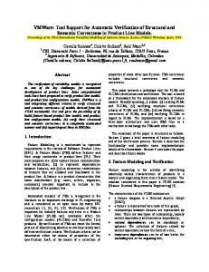
system verification. This paper presents a tool —TABU (Tool for the Active Behaviour of UML)— to carry out this integration by providing a formal framework in which to verify the UML active behaviour. The tool uses SMV [4] (Symbolic Model Verifier) like formal specification, as it has the adequate characteristics for representing the active behaviour of a specification in UML. The main reason for this is that it is based on labeled transition systems and because it allows the user’s own defined data types to be used, thus facilitating the definition of variables. It also uses symbolic model checking for the verification, which means that the test is automatic, always obtains an answer and more importantly, should the property not be satisfied generates a means of identifying the originating error. The tool carries out, with no intervention on the user’s part, a complete, automatic transformation of the active behaviour specified in UML into an SMV specification, focusing mainly on reactive systems in which the active behaviour of the classes is represented through state diagrams, while activity diagrams are used to reflect the behaviour of class operations. XMI [6] (XML Metadata Interchange) is used as the input format, thus making it independent of the tool used for the system specification. On the other hand, the tool has a versatile assistant that guides the user in writing properties to be verified using temporal logic. The verification is carried out in such a way that the user needs no knowledge of either formal languages or temporal logic to be able to take advantage of its potential; something which has traditionally been difficult to overcome when deciding on the use of formal methods. In addition, notions of the form of the specification obtained are unnecessary: that is, knowledge of the internal structure of variables or modules obtained is not required for verification. Figure 1 is a graphical representation of the tool’s architecture, the engineer only need knowledge of UML and the system studied, the tool obtain automatically the formal representation in SMV from textual representation in XMI. Parallel, a wizard helps to write properties to verified using LTL (Linear Temporal Logic), moreover if the property is not satisfied, the tool shows a counterexample trace. The rest of the paper shows the functionalities of the tool illustrated through a case study. It is analysed in terms of two main aspects of the tool: how to obtain a formal specification from the UML diagrams, and how the assistant helps and guides in verifying properties. This is followed by a review of the work in the same field from the literature and, finally, the conclusions are presented along with possible fu-
updateBalanceATM
Engineer
Para poner a prueba la utilidad de la transformación realizada, así como su validez, es necesario verificar la especificación de un sistema que recoja todas las características de UML, y que permita concluir que la transformación en SMV, del comportamiento activo de una especificación realizada en UML, es correcta. Con el fin de que esta comprobación se realice de forma progresiva, se ha elegido la representación de un mismo sistema desde distintos niveles de profundidad, de forma que se comprueben cada uno de los aspectos tratados en la transformación. Pudiéndose llegar a la conclusión que el comportamiento activo reflejado en la especificación en UML se corresponde con el reflejado en SMV. Para realizar esta comprobación se elegirán propiedades temporales adecuadas que permitan asegurar la corrección de la especificación. La especificación en SMV obtenida para cada uno de los sistemas puede encontrarse en el apéndice~\ref{smvEjemplos}. Como punto de partida se utiliza un sistema conocido que refleja el comportamiento de un cajero automático. Este sistema será visto desde distintas pers\-pec\-ti\-vas, comenzando por un pequeño nivel de detalle, el cual será refinado incorporándole características más complejas que permitan concluir en una vista detallada del sistema. El objetivo que se persigue, es que la mayoría de los comportamientos que pueden reflejarse en una especificación en UML, se encuentren también en alguno de los casos de ejemplo. Por ello, junto con el sistema del cajero automático, se presenta el sistema de una fotocopiadora que permite comprobar que los estados de historia funcionan correctamente.
cajero
entorno
activo
inactivo
introTarjeta introPin[cajero.contError < 3] entry / cajero.contError=0 pulsarCancelar introTarjeta introPin 3] esperaPin
expulsarTarjeta
or tErr .con ero [caj
=
comprobar Pin
errorPin / cajero.contError = cajero.contError +1
pinCorrecto
retenerTarjeta entry / retenida
identificarTarjeta
Class diagram sacarTarjeta
/ actualizarSaldoCajero
obtenerPinAlmacenado
esperaOpe racion
after 2
exit / expulsarTarjeta
obtenerPinIntroducido
decodificarPinAlmacenado
botonOperacion
comprobarSaldo
State diagrams comprobacionErronea
retained
La verificación de todas estas especificaciones no se limitará ú\-ni\ca\-men\-te a la comprobación de la validez de la transformación realizada a SMV. No hay que olvidar, en ningún momento, que el principal objetivo de esta tesis consiste en integrar la utilización de métodos formales (SMV) con un método semi-formal ampliamente utilizado y reconocido, UML, de manera semi-transparente al usuario. De forma que sea posible aprovechar las ventajas de los métodos formales, que permiten realizar pruebas formales del sistema, en las fases iniciales del desarrollo de software, adelantando en la medida de lo posible la detección de errores, sin tener el inconveniente de que sea necesario conocer un método formal en el que realizar la especificación del sistema y la especificación de propiedades.
Unisys.JCR.2 1.3.4 ejemplo1Modificado1
introPin() introTarjeta() pulsarAceptar()
pinCorrecto
(natural lenguage)
errorEnd
compararPines
.xmi
[contPinCorrecto >= 2]
comprobacionCorrecta
Activity diagrams Rest diagrams
From XMI to SMV
Assistant for writing properties
Ausencia Globally Before R After Q Between Q and R After Q until R
[](!P) R -> (!P U R) [](Q -> [](!P)) []((Q & !R & R) -> (!P U R)) [](Q & !R -> (!P W R))
Existencia Globally Before R After Q Between Q and R After Q until R
(P) !R W (P & !R) [](!Q) | (Q & P)) [](Q & !R -> (!R W (P & !R))) [](Q & !R -> (!R U (P & !R)))
Universalidad Globally Before R After Q Between Q and R After Q until R
[](P) R -> (P U R) [](Q -> [](P)) []((Q & !R & R) -> (P U R)) [](Q & !R -> (P W R))
Properties to check
UML Tool
(Rational, Argo, ...)
Ok error
returnCard
introPin
1 1
errorPin
2 1
3 1
estCajero inactivo inactivo inactivo estTarjeta
activo
estCajero inactivo
4 1
|:5 1
6 1
activo
activo
activo
activo
activo
activo
inactivo
activo
inactivo
activo
inactivo
activo
inactivo
7 1 activo
8 1 activo
9:| 0 activo
inactivo inactivo inactivo inactivo activo
inactivo
1
1
1
1
1
1
1
1
0
1
1
1
1
1
1
1
1
0
introCard
pushCancel
pushOperation
X(~TarjetaInstancia.en_compararPines
TarjetaInstancia.en_decodificarPinAlmacenado))); prop7_6: assert G(errorPin -> X(cajeroInstancia.en_comprobar)); prop8_6: assert G(finTratamientoError -> X cajeroInstancia.en_esperaPin); prop9_6: assert G(retenida -> X cajeroInstancia.est_comprobarErrores = DontKnow);
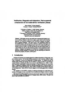
Figure 2: Class diagram
Cadence SMV Model Checker
(Automatic Verification)
TABU
Automatic Manual Aid
active inactive entry / ATM.errorCounter=0
introCard (tr_G_4)
introPin errorPin updateError
retained
(tr_G_16)
The tool input is a UML specification which has been formatted using the XMI exchange syntax. From this input, a SMV specification is automatically generated. Three kinds of diagram are taken into account when transforming the active behaviour from UML into SMV: class, state and activity diagrams. The first provides information concerning the elements that make up the system and their relationships, while the second and third provide information about the behaviour, through time, of each of those elements. In order to show how the tool works we use the example of an automatic teller machine (figures 2, 3, 4, the diagrams of card class have been omitted by fault of space), both because it is a very well known example, and because it incorporates in its specification most of the existing building blocks of statemachine and activity diagrams. The following is the basic description of the system. First of all, the user introduces the credit card followed by a pin number. The system checks whether it is correct and, if not it allows the user to try again. If the user introduces three consecutive wrong pin numbers, the card will not be returned to the user. Once the right pin is introduced, the user will be allowed to push the operation button. This operation updates the card information including the available left-over. At any time, the user can push the cancel button that will make the card to be returned and an error signal to be generated.
CLASS DIAGRAM
The fundamental concept taken as our starting point is that of the active class. The system is specified in terms of active classes which are associated to the reception of signals. The behaviour of each active class is reflected in a different SMV module, which in turn is instantiated in the main module by each of the class objects. Each SMV module, representing a class, needs the signals the class receives as its input parameters, and those the
(tr_G_7)
returningCard
waitOperation
exit / returnCard (tr_G_12)
FROM UML TO SMV
Okpin
do / checkErrors
(tr_G_29)
ture work.
checkingPin
waitPin
Figure 1: Tool architecture
3.
(TarjetaInstancia.en_obtenerPinIntroducido & ~TarjetaInstancia.en_compararPines & U
Temporal logic properties
Counterexample trace
2.
checkPin()
F(TarjetaInstancia.en_obtenerPinAlmacenado & X F TarjetaInstancia.en_obtenerPinIntroducido)); prop6_6: assert F(TarjetaInstancia.en_compararPines) -> (~TarjetaInstancia.en_compararPines
OK
errorPin
U
/***** Instance of class: Tarjeta *****/ TarjetaInstancia:Tarjeta(finTratamientoError, pulsarCancelar, /***** Instance of class: cajero *****/ cajeroInstancia:cajero(introPin, introTarjeta, error, /**************************************************/ /******************* Properties *******************/ /**************************************************/ prop1_6: assert G(TarjetaInstancia.en_operativa & introPin & ~retenida -> X (TarjetaInstancia.en_identificarTarjeta)); prop2_6:assert G(pinCorrecto -> F TarjetaInstancia.en_comprobarSaldo); prop3_6: assert G(TarjetaInstancia.en_comprobarPin & retenida -> X(TarjetaInstancia.est_comprobacionPin = DontKnow)); prop4_6: assert G(TarjetaInstancia.en_obtenerPinAlmacenado -> TarjetaInstancia.en_obtenerPinIntroducido); prop5_6: assert G(TarjetaInstancia.en_identificarTarjeta -> F(TarjetaInstancia.en_obtenerPinAlmacenado & X F TarjetaInstancia.en_obtenerPinIntroducido)); prop6_6: assert F(TarjetaInstancia.en_compararPines) -> (~TarjetaInstancia.en_compararPines U (TarjetaInstancia.en_obtenerPinIntroducido & ~TarjetaInstancia.en_compararPines & X(~TarjetaInstancia.en_compararPines U TarjetaInstancia.en_decodificarPinAlmacenado)));
pinCorrecto
errorPin
TarjetaInstancia.en_obtenerPinIntroducido); prop5_6: assert G(TarjetaInstancia.en_identificarTarjeta ->
expulsarTarjeta:boolean; actualizarSaldoCajero:boolean; retenida:boolean; error:boolean; correcto:boolean; finTratamientoError:boolean; /**************************************************/ /**************** Class instances *****************/ /**************************************************/
.smv
enviroment
X(TarjetaInstancia.est_comprobacionPin = DontKnow)); prop4_6: assert G(TarjetaInstancia.en_obtenerPinAlmacenado ->
pinCorrecto:boolean; errorPin:boolean; actualizarSaldoTarjeta:boolean;
OkPinCounter: 0..6 = 0 introPin() introCard() returnCard() retained() pushOperation() error() ok()
(TarjetaInstancia.en_identificarTarjeta)); prop2_6:assert G(pinCorrecto -> F TarjetaInstancia.en_comprobarSaldo); prop3_6: assert G(TarjetaInstancia.en_comprobarPin & retenida ->
introTarjeta:boolean; botonOperacion:boolean; introPin:boolean; pulsarCancelar:boolean;
Card
errorCounter: 0..3 = 0 introPin() introCard() OkPin() errorPin() PushOperation() pushCancel() updateBalanceCard() checkErrors()
prop1_6: assert G(TarjetaInstancia.en_operativa & introPin & ~retenida -> X
/**************************************************/ /************** Signal Declarations **************/ /**************************************************/
updateBalanceCard
ATM
property patterns /**************************************************/ /****************** Main Module *******************/ /**************************************************/ MODULE main() {
OkPin
pushOperation (tr_G_9)
pushCancel / error / ok
(tr_G_13) checkBalance
checkCard
checkATM
updateBalanceCard (tr_G_38)
/ updateBalanceATM (tr_G_44)
checkBalanceCard
updateATM
(tr_G_46) checkBalanceATM
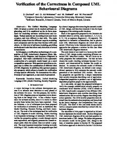
Figure 3: State diagram of the ATM class
class emits as output parameters. Thus, the said signals are reflected in the class diagram using the stereotypes and as shown in figure 2. Here, the signals okPin, errorPin and updateBalanceCard correspond the the signals emitted by the Card class, while introPin, introCard and returnCard are the ones it receives. An additional class called environment also has to be included. It has no associated behaviour and contains details of the signals produced outside the system and which are input signals.
4. STATE MACHINES Behaviour of each of the active objects is reflected through state machine and activity diagrams. To correctly control the evolution of a state machine, the state it is in at any given moment must be known. This is achieved by using a separate variable to store this information for each machine. In addition, the fact that combined states, both sequential and concurrent, may appear within a machine means that additional variables are needed in order to deal with the submachines. These will be dealt with following the same reasoning as for the main machine, with the exception of the peculiarities they possess with respect to activation and deactivation. As for the evolution machines, the SMV operator next is used. This represents the value taken by the variable in
the following step. The state machine is initiated using the init operator. As far as the machine for the ATM class is concerned (see Figure 3), the SMV representation of the outermost machine behaviour is as shown below: /***** Statemachine for state: ATM *****/ st_ATM:{checkBalance,waitOperation,active,inactive,returningCard}; /***** Evolution of statemachine for class: ATM*****/ init(st_ATM) := inactive; next(st_ATM) := case { tr_G_9 : checkBalance; tr_G_7 : waitOperation; tr_G_4 : active; tr_G_29 | tr_G_16: inactive; tr_G_12 | tr_G_13: returningCard; default : st_ATM; };
Where tr_G_9, tr_G_7, tr_G_4. . . represent the firing of transitions tr_G_9, tr_G_7, tr_G_4. . . The block default represents the behaviour where there is no change of state, that is, when no transition present in the machine is fired and it remains in the same state during the following step. A similar reasoning has been used for the behaviour of the submachines, based on having a different machine for each sequential composite state and for each region of a concurrent composite state. By doing so, the behaviour associated to the concurrent composite state checkBalance of Figure 3 is represented in terms of the following machines: /***** Statemachine for state: checkBalanceATM *****/ st_checkBalanceATM :{updateATM,checkATM,FINAL,DontKnow}; /***** Statemachine for state: checkBalanceCard *****/ st_checkBalanceCard :{checkCard,FINAL,DontKnow}; /** Evolution statemachine state: checkBalanceATM ***/ init(st_checkBalanceATM) := DontKnow; next(st_checkBalanceATM) := case { tr_G_12 | tr_G_13 : DontKnow; tr_G_9 : checkATM; tr_G_44 : updateATM; tr_G_46 : FINAL; default : st_checkBalanceATM; }; /** Evolution statemachine state: checkBalanceCard ***/ init(st_checkBalanceCard) := DontKnow; next(st_checkBalanceCard) := case { tr_G_12 | tr_G_13: DontKnow; tr_G_9 : checkCard; tr_G_38 : FINAL; default : st_checkBalanceCard; };
Where DontKnow is the state of a machine which is deactivated. Deactivation can take place either because of the firing of transition tr_G_13, the cancel button is pushed, or because both submachines reach the final state and tr_G_12 is fired by termination. Its syntax is the following: tr_G_12:=in_checkBalance & in_FINALcheckBalanceATM & in_FINALcheckBalanceCard;
5.
ACTIONS
The evolution of an active object can lead to different actions, including sending signals and modifying the value of class attributes. With regard to sending signals, it can happen in any of the following situations: (1) the firing of a transition, if the signal is among the transition effects; (2) the activation of a state, if the signal is among its entry actions; and (3) the deactivation of a state, if the signal is among its exit actions. Taking into account that both state activation and deactivation are due to the firing of some transition, signal evolution can be represented in a similar way to state machine evolution.
checking
[ATM.errorCounter >= 2] / retained
(tr_G_55)
retaining
[ATM.errorCounter < 2] / ATM.errorCounter = ATM.errorCounter +1, errorEnd
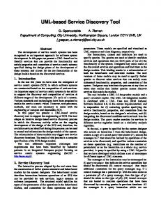
Figure 4: Activity diagram for the activity checkErrors
As for modifying the value of an attribute, very much the same philosophy can be followed. This means that it will be specified through the use of the SMV operators init and next. Attributes will be initialised with init if they have an initial value in the class diagram, whereas their evolution (next) will depend on the firing of transitions. For instance, the SMV behaviour for the attribute errorCounter in class ATM, which keeps track of how many wrong consecutive pin numbers have been introduced, is the following (see Figures 2, 3 and 4). /***** Attribute: errorCounter *****/ ATM_errorCounter: 0..3; init(ATM_errorCounter):=0; next(ATM_errorCounter) := case { tr_G_55: ATM_errorCounter +1; tr_G_29 | tr_G_16: 0; default : ATM_errorCounter; };
6. VERIFICATION Having obtained a system specification in a formal language with a solid mathematical basis means that it is possible to check whether the system complies with certain desirable properties. As with the formal specification methods, the increasing complexity of software systems requires the development of new verification methods and tools to carry it out either automatically or semi-automatically. In our tool, verification is carried out using the SMV tool model checker. With this, it is possible to make the verification process completely automatic. That is, given a property, a positive or negative reply is always obtained. The property must be expressed in a temporal logic present in SMV, CTL (Computation Tree Logic) or LTL (Linear Temporal Logic). This property writing is not a trivial problem. To write them correctly, advanced knowledge of logics and the type of specification obtained from the system is necessary. Our tool overcomes this problem as it has an assistant that guides the user through the writing of properties until the property to be verified is finally obtained following the appropriate syntax. Our starting point was the pattern classification proposed by Dwyer et al [2] to which our own cataloguing of the different properties to be automatically verified has been added.
6.1 Property patterns The property writing assistant is based on the pattern scheme proposed by Dwyer et al [2] where it is established a first classification between patterns of occurrence and order. Most of the properties of a system to be verified in practice, fit in with one of these two categories. Occurrence patterns describe properties with respect to
the occurrence of a state or signal during the evolution of a system. These include absence (never), universality (always), existence (sometimes) and bounded existence (appearing a certain number of times). Order patterns establish properties with respect to the order in which they occur. They include: precedence (s precedes p), response (s responds to p), and combinations of both: chain precedence (s and t precede p or p precedes s and t), chain response (s and t respond to p or p responds to s and t), and constrain chain (s and t without z respond to p). On the other hand, each kind of pattern has a scope of application which indicates the system execution on which it must be verified. There are five basic scopes: Global (the entire program execution), Before R (the execution up to a given property), After Q (the execution after a given property), Between Q and R (any part of the execution from a given property to another given property) and after Q until R (like between but the designated part of the execution continues even if the second property does not occur).
6.2 Property classification The different properties to be verified have been catalogued to establish limits for the scopes (Q and R) and to specify the order of properties when more than one must be determined (s, t o z), so that the user does not need to know or understand the structure of the specification obtained in SMV to carry out verification The established property types are: • A state machine is in a particular state. • An object activity is in a particular state. • A signal or event is produced.
8. ADDITIONAL AUTHORS
• Value comparison of an attribute. The tool will automatically generate the property in the adequate format, in accordance with the chosen option and the selected pattern and scopes. Once we have the properties to be verified, it is possible, using the tool itself, to execute the SMV model checker to carry out the verification. If the property is not satisfied, it generates a trace showing a case where it is not verified. For example, for the automatic teller machine, it would be possible to verify that the card is never retained; this means that the signal retained never happens (pattern: absence, scope: global) . As expected, the result of the checker is false. If the generated counterexample trace is analyzed (see next table), it can be seen that the card is retained when there has been 2 wrong pin numbers and again errorPin is generated. Step st_ATM st_active st_checkErrors errorPin ATM_errorCounter retained
7.
62 active checkingPin DontKnow 1 2 0
63 active updateError checking 0 2 0
be transparent for the user. It verifies the UML active behaviour using SMV. Although this is not a new idea —there are other works that use formal methods to verify the behaviour of UML specifications [7, 1, 8]— as far as we know at the present time, nowhere are activity and state diagrams jointly verified, using the former to represent the behaviour of the class operations. However, the most innovative characteristic of the tool is that, in spite of using the potential of temporal logic to verify systems, the user need have no knowledge of all the technical intricacies of such logics. Most of the former related works do not verify automatically, except vUML [7] although it doesn’t fully exploit the use of temporal logics, implementing a limited verification based on checking that it is impossible to reach error states. These error states are introduced by the user in the diagrams, so the diagrams are more complicated. It should also be pointed out, though it has not been discussed here through lack of space, that the representative elements of both state and activity diagrams are included in this approach, something that cannot be said of other contributions in this field, in which few of the characteristics provided by UML (history states, deferred events, transitions fired by termination...) are dealt with. As for future lines of work, some kind of treatment of the traces obtained in the verification when the property is not satisfied would seem to be of great interest. More precisely, that the representation of the traces should be visual instead of written, by using either some of the UML diagrams or an animated representation of the state and activity machines which could help the user to locate the error source very quickly.
64 active updateError BRANCH 0 2 0
|:65 active updateError retaining 0 2 1
CONCLUSIONS AND FUTURE LINES OF WORK
This paper presents a tool whose main aim is to integrate formal methods with semi-formal ones in such a way as to
Additional authors: Pablo de la Fuente (Universidad de Valladolid) email:
[email protected])
9. REFERENCES [1] A. Darvas, I. Majzik, and B. Beny. Verification of UML Statechart Models of Embedded Systems. In Proc. 5th IEEE Design and Diagnostics of Electronic Circuits and Systems Workshop (DDECS 2002), IEEE Computer Society TTTC, pages 70–77, Abril 2002. [2] M. B. Dwyer, G. S. Avrunin, and J. C. Corbett. Patterns in Property Specifications for Finite-State Verification. In Proceedings of the 21st International Conference on Software Engineering, Mayo 1999. [3] J. R. G. Booch and I. Jacobson. The Unified Modeling Language. Addison-Wesley, 1999. [4] K. L. McMillan. Symbolic Model Checking. An approach to the state explosion problem. PhD thesis, Carnegie Mellon University, Mayo 1992. [5] OMG. UML 2.0 Diagram Interchange Final Adopted Specification. OMG Document pct/03-09-01, 2003. [6] OMG. XML Metadata Interchange (XMI) v 2.0. OMG Document 2003-05-02, 2003. [7] I. Porres. Modeling and Analyzing Software Behavior in UML. PhD thesis, Department of Computer Science, ˚ Abo Akademi University, Noviembre 2001. [8] W. Shen, K. Compton, and J. Huggins. A Toolset for Supporting UML Static and Dynamic Model Checking. pages 147–152. IEEE Computer Society, 2002.