UML-Based Robotic Speech Recognition Development: A Case Study Abdelaziz A.Abdelhamid and Waleed H.Abdulla Electrical and Computer Engineering, University of Auckland, New Zealand E-mail:
[email protected],
[email protected]
Abstract—The development of automatic speech recognition (ASR) systems plays a crucial role in their performance as well as their integration with spoken dialogue systems for controlling service robots. However, to the best of our knowledge, there is no research in the literature addressing the development of ASR systems and their integration with service robots from the software engineering perspective. Therefore, we propose in this paper a set of software engineering diagrams supporting a rapid development of ASR systems for controlling service robots. The proposed diagrams are presented in terms of a case study based on our speech recognition system, called RoboASR. The internal structure of this system is composed of five threads running concurrently to optimally carry out the various speech recognition processes along with the interaction with the dialogue manager of service robots. The diagrams proposed in this paper are presented in terms of the COMET method which is designed for describing practical and concurrent systems.
I. I NTRODUCTION Service robots could recently attract the attention of both academic and industry domains [1], [2], [3], [4], [5]. These robots are designed to assist humans performing services (i.e., medical services [5]). Therefore, it is essential for these robots to provide a human-robot interaction (HRI) using natural speech through speech recognition technology. However, this capability is still not widely spread for service robots due to either the limited resources available by these robots or the difficultly of integrating speech recognition systems with the dialogue managers of these robots [6]. Service robots assisting older people in particular received a lot of attention because of the dramatic increase in the ageing population as well as the increase of the costs of the elderly care [7], [8], [9]. Some of these service robots have been developed as outcomes of several projects initiated in the developed countries [7], [10]. In this regard, the R&D program of the Korea Ministry of Knowledge and Economy (MKE) and Korea Evaluation Institute of Industrial Technology (KEIT) with the cooperation of the University of Auckland started a new project to develop a service robot for presenting medical services for older people [5]. In this project, when building a software for a service robot, it is essential to develop a well-defined software architecture as well as integrating the software components with the robot in a comprehensive way. The software components of robotic systems are usually related together in the form of many-to-many relations. Therefore, the interaction among these components must be carefully analysed and managed from an early stage of the development to understand the full picture of the complete system. As the developed speech
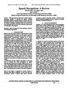
recognition system is part from this project, it was of a high importance to develop it in a systematic way to enable other members of the team to easily integrate it with the other software components. To the best of our knowledge, there is no research in the literature addressing the systematic development of speech recognition systems for controlling service robots from the software engineering perspective. Therefore, this paper presents a systematic analysis of the development of robotic speech recognition systems based on the COMET method and in terms of the developed speech recognition system, RoboASR [11], as a case study. In this analysis the Tripodal schematic architecture presented in [12], [13] was employed. This architecture gives a rigorous viewpoint about the internal components of the developed system as well as the external components interacting with the system components. This paper is organized as follows. An overview of our service robot and the supported services are presented in Section II. The description of the speech recognition system, RoboASR, and its integration with HealthBots service robot are described in Section III. The analysis of the developed speech recognition system is then discussed in Section IV based on the COMET method, followed by a discussion in Section VI. Finally, the conclusion of this work comes in Section VI. II. BACKGROUND ON H EALTH B OTS SERVICE ROBOT A. Robot platform Our HealthBots service robot is shown in Fig. 1. This robot is designed for presenting medical services for older people. On of the key features of this robot is the speech capabilities, such as speech recognition and speech synthesis. This robot is sponsored by the HealthBots project1 as a joint development of the University of Auckland in New Zealand, with ETRI and Yujin Robot Co. Ltd., in South Korea. The HealthBots service robot is powered by a 24v Li-Polymer battery. It consists of bumper sensors, ultrasonic sensors, microphones, a rotatable touch screen and a laser range finder. The dialogue manager of this robot is developed using ActionScript. The software provided by this robot is communicated with several web-services for information retrieval and update, and is integrated with third-party applications for providing added functionalities. User inputs are received in terms of spoken 1 https://wiki.auckland.ac.nz/display/csihealthbots
commands directed through a head mounted microphone or through buttons on a touch screen. The robot then responds to the user inputs through synthesized speech, visual output on the touch screen, or through physical movements. Camera & Microphones
Touch screen Pan-tilt enabled Speakers
Medical devices tray Laser scanner
Rotatable body
Fig. 1. HealthBots service robot.
B. Robot services Some of the primary services provided by the HealthBots service robot for older people are described in the following. 1) Multi-modal interaction: The interaction with HealthBots service robot can be established through a visual output on a touch screen and/or voice commands captured using a wireless microphone. 2) Medication reminding: Our robot provides also a medical reminding service for older people. This service allows doctors to remotely follow up the health status of older people. 3) Vital signs measurement: Three vital signs measurements are supported by this robot. These vital signs include blood pressure, blood oxygen, and blood glucose. 4) Autonomous navigation: The user can command the robot to move to a specific position in a predefined map. The navigation is performed using a set of laser and ultrasonic sensors with the help of ceiling landmarks. Of these services, we emphasize in this paper on the speech recognition system as a challenging approach in multimodal interaction with service robots. This system performs several processes, such as signal acquisition, voice activation detection, feature extraction and speech decoding as well as communication with the robot’s dialogue manager. More details about this system are presented in the following section. III. ROBOASR: T HE SPEECH RECOGNITION SYSTEM The analysis proposed in this paper is presented in terms of the speech recognition system, RoboASR [14][11][15]. In comparison to other promising systems [16][17], our speech recognition system has the advantage of being applicable to
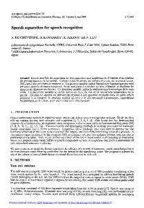
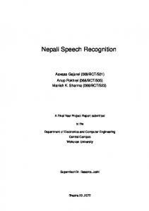
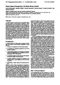
service robots with limited resources. The developed speech recognition system is fully implemented in C++, and the currently supported operating system is Windows. This speech recognition system is based on multi-threads as an efficient way to achieve a harmony in the processing of the various operations that take place on the captured speech signal. The use of multi-threads also allows a continuous capturing of and audio stream which enables an automatic speech decoding of the detected speech regions. The structure of RoboASR, shown in Fig. 2, is based on the following five threads. 1) Control thread: This thread is developed to control the overall system. It is also responsible for loading a set of acoustic models as well as a set of tiny decoding graphs, which are loaded on-demand, for speech decoding. 2) Monitoring thread: We developed this thread to keep the speech recognition system updated with the last changes occurred to a set of extensible markup language (XML) files containing the potential spoken commands at each point of the robotic interaction scenarios. 3) Signal acquisition thread: The continuous capturing of the speech signal from the sound card is the task of this thread. The speech signal is captured using a series of multi-buffers working together as a pipeline. 4) Preprocessing thread: While capturing the continuous audio stream, this thread is responsible for detecting the buffers containing parts of the spoken command. The detected buffers are then accumulated into another large buffer for further speech decoding after and extracting a set of acoustic features. 5) Speech decoding thread: The actual recognition process (also referred as speech decoding) is performed using this thread. The recognition process is realized using Viterbi beam pruning algorithm. The recognition command is then sent to the robot’s dialogue manager to react accordingly. A. RoboASR integration with HealthBots service robot A service robot should be enabled to interact and transact providing its own functionalities and those of other devices to humans. Speech recognition is a common and natural choice to perform this task. The interaction scheme of the developed speech recognition system with the dialogue manager of HealthBots service robot is shown in Fig. 3. This scheme is based on the following components. 1) Speech decoding: This component refers to the singlepass decoder, which is responsible for decoding the detected speech regions in the continuous audio stream. Speech decoding is performed in terms of a tiny decoding graph corresponding to the state identifier of the accessed HRI state. In other words, once an HRI state is accessed, its identifier is sent to the decoding engine to load the corresponding tiny decoding graph. Consequently, the decoding engine expects only the potential spoken commands defined at this HRI state. In addition, once the spoken command is recognized by
Control Thread
Monitoring Thread
Signal acquisition Thread
Preprocessing Thread
Is speech?
... No
Bufferi
Changes detected?
Yes
Buffer
Buffer1
Speech decoding Thread
Speech decoding
No ... BufferN
Yes
No Update tiny decoding graphs
Get next buffer
Command ready?
Yes Feature extraction Tiny decoding graphs
Fig. 2. Architecture of the developed speech recognition system.
the decoding engine, it is sent to the dialogue manager to react accordingly. 2) XML Parser: The files containing the interaction scenarios (represented in XML scripts) are parsed by this parser to generate a set of weighted finite state acceptors (WFSAs) corresponding to the changed or newly added spoken commands at each HRI state. 3) Tiny WFSTs extraction: This component is responsible for extracting a tiny WFST for each WFSA generated by the parser. The resulting tiny WFST are then added to a pool containing the tiny WFST used in speech decoding.
Dialogue Manager
RoboASR
Dialogue Definitions (XML)
HRI State Identifier
Recognized Command
XML parser
Speech decoding
Tiny WFSTs extraction
Tiny WFSTs
Offline
Online
Fig. 3. The integration of the developed speech recognition system with the dialogue manager of HealthBots service robot.
It is worth noting that the extraction of the tiny decoding graphs is performed in an offline mode to speed up the robot’s
response to the user input. However, as the dialogue moves from one HRI state to another, the corresponding tiny decoding graph is loaded in an online mode. B. The COMET method The analysis presented in this paper is based on the COMET method [18], which is developed for analysing real-time and distributed applications. This method integrates object oriented and concurrent concepts in the form of unified modelling language (UML) notations [19]. The COMET object oriented software life cycle model is a highly iterative software development process based around the usecase concept and consists of the following modelling stages. 1) Requirement modelling: In this modelling stage, the system functional requirements are modelled using actors and usecases. 2) Analysis modelling: This modelling focusses on developing both static and dynamic models of the system. The static model defines the structural relationships among problem domain classes. A dynamic model is then developed in which the usecases from the requirements model are refined to show the objects that participate in each usecase and how they interact with each other. 3) Design modelling: This modelling is concerned with the design of the system software architecture. Using this design, the operational environment is mapped from the analysis model. IV. A PPLYING THE COMET TO ROBOASR The analysis of the developed speech recognition system is explained in this section in terms of the COMET method.
A. Requirements modelling In the stage of modelling the system requirements, black boxes are usually used to represent the main functions of the system. These black boxes are denoted by usecases. The usecase model, shown in Fig. 4, is developed to represent the whole system process. In this figure, a set of usecases and actors are used to represent the functions (i.e., functional requirements) provided by the system. An actor is usually used to represent a human user. However, it may also represent an external I/O device or a timer in real-time systems [20].
Commander (from 1.0 Actors)
ASR >
Definitions Monitoring
Clock (from 1.0 Actors)
Fig. 4. Usecase diagram of the developed speech recognition system..
The developed ASR system has two actors; the first represents the commander, who is the user of the system, and the second actor represents the clock that schedules the definition monitoring process. In addition, two usecases are defined, the first represents the speech recognition process, ASR. While the other represents the process of monitoring a set of definition files containing the potential spoken commands. The latter usecase is called Definitions Monitoring. This modelling stage is based on function requirements defined in the following. The first function requirement is to receive a spoken command from the commander, then recognize it, and finally send the recognized command to the robot’s dialogue manager to behave accordingly. Therefore, the first usecase was defined as ASR to represent the whole process of the speech recognition. As the speech recognition/decoding process is performed in terms of a set of tiny decoding graphs [11] corresponding to the potential spoken commands expected at each HRI state, the second function requirement was to keep these tiny decoding graphs updated with the latest changes occurred to the definition files containing these potential spoken commands. Therefore, the other usecase, Definitions Monitoring, was defined to represent the continuous monitoring of the changes that may occur to definition files and to keep the ASR usecase aware of these changes. Therefore, the ASR usecase is extended to the other usecase Definitions Monitoring. B. Analysis modelling The modelling of real-time systems consists of two types, namely static and dynamic modelling. In this section, both of these modelling types are discussed in more details.
1) Static modelling: This modelling process is used to represent the static relationships in the context of the speech recognition system. For real-time systems, it is important to understand the relationship between the system and the external environment. This relationship is usually described using a system context [20], which provides the boundary of the system. The static modelling is used to determine the system context in terms of the external classes connected to the system. Figure 5 shows the context diagram of the developed system. In this diagram, the commander utters a spoken command, which is captured using a wireless microphone. Once the spoken command is captured, it is recognized and sent to the robot’s dialogue manager to do some action. Therefore, the system is depicted as an aggregate class with the stereotype, , and the external environment is depicted as the external classes by using stereotypes. These external classes are, graphical user interface (GUI) as the external user class, wireless microphone as an external input device, and service robot as an external output device. Also, an external timer class, called clock, is required for the clock actor to provide the system with timer events, so that the system periodically checks the files changes to avoid any inconsistencies. Afterwards, to determine the software objects of an ASR system in preparation for dynamic modelling, object structuring criteria, provided in the COMET method, are applied for the purpose of decomposing the system into classes and objects. In our system, a set of external classes interfacing with the system are used to determine the interface objects including GUI, signal acquisition, and dialogue manager interfaces. We identified four entity objects including spoken command, acoustic features, best decoding hypothesis, tiny decoding graphs, that are defined as long-living objects used to store information in the developed system.
Interacts with
> 1 1 Graphical User Interface 1 1 Commander (from 1.0 Actors)
Outputs to > ASR 1
1
Inputs to
1 .. * > Wireless Microphone
> Service Robot
1 1
Awakenes 1
> Clock Clock (from 1.0 Actors)
Fig. 5. Context class diagram of the developed speech recognition system.
Additionally, a set of control objects, such as statedependent control, or timer objects, are used to describe the coordination of objects in a usecase. For the developed system, a state-dependent control object, called ASR Controller, is identified, which controls the speech recognition process. Also, a timer object is identified to periodically check the status of the scenario definition files. This timer generates a timer event periodically and every fixed portion of time (i.e. 50 ms). On the other hand, the updates to speech decoding graphs
Delibrate Layer
> 1.1: Access HRI State
: TouchScreen
>
: GraphicalUserInterface
Sequencing Layer
1.2: HRI State
>
: Feature Extraction
3.6: Extract Features
>
: Acoustic Features
3.7: Features Extracted
3.5: Get Features
5.1 Extract Graph
>
: Graph Extraction
: Token Passing 4.3: Best Decoding Hypothesis
4.5: Best Hypothesis
: ASR Controller
1.3: Load Tiny Graph
3.1: Capture Command
>
>
: TinyGraph 1.4: Tiny Graph
>
: Best Hypothesis
4.1: Get Best Hypothesis
3.8: Features
4.2: Decode Features
>
>
3.2: Listen
>
: Spoken Command
3.4: Command
5.2 Graph Extracted
: VAD 3.3: Captured Command
Reactive Layer
2.4 Audio Data 2.1 Read Audio
6.1 Best Hypothesis 6.4 Hypothesis Ack
>
: Microphone
> 2.2 Read
>
: SignalAcquisitionInterface
: DialogManagerInterface
6.2.a Start 6.2.b Stop
>
: ServiceRobot
6.3.a Started Ack 6.3.b Stopped Ack
2.3 Data
Fig. 6. Collaboration diagram of the ASR usecase.
Sequencing Layer
>
Reactive Layer
1.7 Tiny Decoding Graphs Updated
>
>
: Clock
: DefinitionsMonitoringTimer
4.1: Hypothesis Ack
1.6 Update Tiny Decoding Graphs
4.2: Best Hypothesis
: ASR Controller
1.1 Timer Event 1.5 Paused > 2.1 Read
: Microphone
1.4 Pause
1.2 Notify
1.3 Notified >
: SignalAcquisitionInterface
2.2 Data
>
: DialogManagerInterface
3.1.a Start > 3.1.b Stop
: ServiceRobot
3.1.a Started Ack 3.2.b Stopped Ack
Fig. 7. Collaboration diagram of the Definitions Monitoring usecase.
are performed by a timer event once any changes are detected in these definition files. Also, voice activation detection (VAD), feature extraction and token passing algorithm objects
are described as an encapsulated algorithms usually used in speech recognition systems. As the object’s behaviour varies in each of its states, the next section presents an analysis of
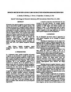
the dynamic modelling of the ASR control object. 2) Dynamic modelling: The dynamic modelling process is used to emphasize the dynamic behaviour of the speech recognition system. This modelling process plays an important role in the analysis of concurrent and real-time systems [20]. In dynamic modelling, the contribution of the system objects to the usecases as well as the interaction between these objects are described. Additionally, the dynamic modelling process presents the definition of state-dependent objects in terms of a finite-state machine called state-chart. This modelling approach starts with describing the objects of usecases, ASR and Definitions Monitoring, that are identified during the static modelling, using collaboration diagrams. Then, statechart diagram is developed for collaborations having statedependent objects. Figure 7 illustrates the collaboration diagram of the Definitions Monitoring usecase. In this figure, the object interactions of this usecase start with a timer event received from the clock. If this event indicates that the definition files have been changes, a notification is sent to the dialogue manager to inform it that the speech recognition system will start updating its decoding graphs. In addition, a message is sent to the SignalAcquisitionInterface object to pause capturing the audio stream. Finally, a message is sent to the ASR Controller to start updating the tiny decoding graphs based on the changes occurred to the definition files. On the other hand, Fig. 6 depicts the collaboration diagram of the ASR usecase. In this figure, the object interactions of the ASR usecase start with the commander accessing an HRI state. The identifier of the accessed state is provided to the ASR controller through the GUI. Also, a set of messages sequences, each of which is assigned to separate thread, are passed between the objects of the collaboration diagram as follows. The message sequence starting from 1.1 to 1.4 is used to address the loading of the decoding graph corresponding to the accessed HRI state. The next message sequence starts from 2.1 to 2.2, is used to capture an audio stream. Followed by the message sequence starting from 3.1 to 3.8 corresponding to voice activation detection and extraction of acoustic features. Then, the message sequences from 4.1 to 4.5, from 5.1 to 5.2 and from 6.1 to 6.4 are used for handling the decoding process, extraction of tiny decoding graphs and sending actions to the service robot. A state-chart diagram is then defined for each control object in the collaboration diagram. The state-chart diagram contains a set of states connected with each other using a set of messages. These message may carry an information or a function call. The messages of state-chart and collaboration diagrams should be considered together. In other words, an input event to a control object in the collaboration diagram should coincide with an input message to a state in the statechart. Also, output messages in the state-chart should coincide with output events shown in the collaboration diagram. It worth noting that, a message arriving at the control object causes a state transition. For example, in Fig. 6, GUI sends the 1.1: HRI-state event to ASR Control, and thus a transition
is defined in state-chart from Idle state (the initial state) to Loading Tiny Graph state, as shown in Fig. 8. The action associated with this transition is Load Tiny Graph. This action corresponds to the output events 1.3: Load Tiny Graph in the collaboration diagram. Because the state-chart modelling involves two state-dependent usecases (ASR and Definitions Monitoring), the two partial state-charts are integrated to create the complete state-chart shown in Fig. 8. 3) Software architecture: The collaboration diagrams of each usecase are then merged into a single consolidated collaboration diagram. The consolidation diagram describing the two usecases, ASR and Definitions Monitoring, is depicted in Fig. 9. This consolidated diagram is used to provide a complete description of all objects and their interactions. Using the COMET method, the architecture of software systems can be modelled using client/server or layered architectural style. In this work, the layered architectural style is adopted in the design and modelling of the developed speech recognition system. This style provides three layers, namely deliberate, sequencing, and reactive layers. In the collaboration and consolidated collaboration diagrams shown in Fig. 6 and Fig. 9, the deliberate layer includes the GUI for interfacing with end users. Whereas the reactive layer contains the signal acquisition and dialogue manager interfaces as well as the definition monitoring timer. On the other hand, the sequencing layer contains the other objects that are used in controlling the speech recognition process. This approach is very helpful in arranging various software modules and functions. C. Design modelling This part focuses on the tasks incorporated in the design of the developed system. The following sections discuss this part in terms of two phases, namely task structuring and detailed design. 1) Task structuring: In this phase, the system is structured into concurrent tasks, and the task interfaces and interconnections are defined. In this phase, the terms task and object are used to denote active and passive objects, respectively. Using the COMET method, the mapping between an object-oriented analysis model and a concurrent tasking architecture can be established using task structuring. The tasks included in a system can be determined by understanding how objects in that system interact with each other. This can be determined easily from a consolidated collaboration diagram. According to the consolidation diagram shown in Fig. 9, the token passing object is activated periodically to decode the extracted acoustic features from the acoustic features object, and to return back the best decoding hypothesis to the ASR controller. Therefore, the token passing algorithm is structured as internal periodic algorithm tasks, based on the internal task structuring criteria in COMET, because they are executed on a periodic basis, as shown in Fig. 10. Four passive entity objects, namely spoken command, acoustic features, best decoding hypothesis, and tiny decoding graphs can be viewed in the figure. These passive objects do not need a separate thread of control, and can be described
Idle
Load Tiny Graph
Start Monitoring
Loading Tiny Decoding Graph
HRI State Changed
Monitoring XML Changes
Graph Loaded Signal Captured
Signal Acquisition Resume Acquisition
Voice Activation Detection (VAD)
Changes Detected
Detected Utterance Valid Utterance
Check Detected Utterance
Changes Applied
Feature Extraction Acoustic Features Speech Decoding
Updating Tiny Decoding Graphs
Recognized Command Controlling Service Robot
Fig. 8. State-chart diagram of the developed speech recognition system.
> Navigate HRI states
: TouchScreen
>
: GraphicalUserInterface
Sequencing Layer
HRI State Extract Features
>
: Feature Extraction
>
: Acoustic Features
Features Extracted
Get Features
Features
Extract Graph
: Graph Extraction
>
: TinyGraph Graph Extracted
Reactive Layer
Read Audio
> Read
: Microphone
Audio Data >
: SignalAcquisitionInterface
Data >
: Clock
Paused Ack Timer Event
Best Hypothesis
Pause
>
: Spoken Command
Best Hypothesis Hypothesis Ack >
: DialogManagerInterface
>
>
: Token Passing Best Decoding Hypothesis
Capture Command
Command
Tiny Graph Loaded
Decode Features
: Best Hypothesis
Get Best Hypothesis
: ASR Controller
Load Tiny Graph >
>
>
>
Delibrate Layer
: VAD Detected Command
Start > Stop
: ServiceRobot
Started Ack Stopped Ack
Notify
>
Listen
Notify Ack
: DefinitionsMonitoringTimer
Fig. 9. Consolidated collaboration diagram of the developed speech recognition system.
in terms of data abstractions. On the other hand, microphone device and service robot are considered as passive tasks, as there is no interruption generated by these tasks on the completion of their operations. It worth noting that, by using the task clustering criteria, we can determine the possibility of grouping tasks together to reduce the overall number of tasks, because too many tasks can potentially result in increasing system complexity and execution overhead. The next section describes the characteristics of each task using the task behaviour specification. 2) Detailed software design: In this phase, the information hiding classes are designed. These classed are used in instantiating the passive objects. The design of the interfaces of these classes and the operations of each class can be determined using either static or dynamic models (i.e., collaboration diagrams). They are specified in a class interface specification. To show the information hiding objects, the internal design of the ASR is considered as shown in Fig. 12. The information hiding objects include signal acquisition and dialogue manager interface objects and the GUI object. The communications between the ASR task and Spoken command, Acoustic features and Best competing hypothesis are established through data abstraction classes. In the case of inter-task communication between the ASR and Definitions Monitoring tasks, synchronization is required since these tasks try to access to a shared resource, namely the tiny decoding graphs. In other words, when a change in the scenario definition files is detected by Definitions Monitoring, the task sends a suspend events, such as pauseSignalAcquisition in Fig. 9, to the signal acquisition interface to pause the ASR task that depends mainly on the signal acquisition. Additionally, the sequence of task’s events is described using a task event diagram, as shown in Fig. 11. This figure shows how the task responds to each of its message or event inputs, which is very useful in implementing the tasks and their corresponding events. V. D ISCUSSION In this section, we summarize the lessons learned from applying the COMET method in the development of speech recognition systems for controlling service robots. A. UML for robotic ASR systems Through this case study we leaned that, system requirements, structuring, system decomposition into objects, and communication between objects can be efficiently described and modelled using the COMET approach. This modelling can be established using the following set of diagrams which are important for analysing, modelling and designing real-time systems. 1) Usecase diagram: Using this diagram, the functions or processes of a speech recognition system can be represented in terms of actors who are the users of the ASR system and usecases that are used to define the behaviour of a global task in the ASR system without revealing its internal structure.
2) Collaboration diagram: This type of diagrams is used to model the requirements of usecases defining a system through describing the system objects in terms of their corresponding interactions. This diagram is particularly useful for modelling the architecture of real-time systems. 3) State-chart diagram: The ASR is considered as a state-dependent system, which is the case of most realtime embedded systems. State-chart diagram is used to model state-dependent aspects of the system using finitestate machines. This can help in simplifying the design and development of state-dependent systems. It is also possible for this diagram to model object behaviour over several usecases with the collaboration diagrams. 4) Task event diagram: The interaction between objects arranged in time sequence is described using a task event diagram. In other words, this diagram is used to describe how tasks respond to each of their input events or messages. The order in which messages are passed between tasks can be used to help engineers in implementing the system tasks more efficiently. A significant gain from applying the UML notations to the development of ASR systems is to enable different development teams and research groups to communicate together to develop and integrate the various tasks performed by the ASR system. B. Importance of systematic development of ASR systems In order to efficiently resolve the issues in developing an ASR system and integrating it with a real robotic platform, a systematic and comprehensive software development method has to be employed. In the case study presented in this paper, the COMET method is employed to developing an ASR system for controlling service robots. The advantage of the COMET method is that it is based on the usecase concept in a highly iterative software development process performed through three modelling stages. In the stage of requirement modelling, the global functions of the speech recognition systems are defined as usecases, whereas the objects interacting with the system are defined as actors. In the stage of analysis modelling, each usecase is represented in terms of it constituting tasks along with the interactions among these tasks. Finally, in the stage of design modelling, the concurrency, distribution, and information hiding of each task is further analysed. The case study presented in this paper clarified the importance of applying the COMET method in developing an effective speech recognition system for controlling service robots through carefully handling the technical components of this system along with it integration with the dialogue manager of service robots. VI. C ONCLUSION In this paper, the COMET method is employed to present the development of robotic speech recognition systems in terms of our speech recognition system, called RoboASR, as a case study. The advantage of using the COMET method
Delibrate Layer
>
: TouchScreen
Sequencing Layer
accessHRIState(in HRIState)
>
>
>
>
: Feature Extraction
: Acoustic Features
: Best Hypothesis
: Token Passing
extractFeatures(in Command, out Features)
decodeSpokenCommand(in Features, out BestHypothesis)
: ASR Controller
loadTinyGraph(in HRIState) >
>
: Graph Extraction
: TinyGraph
captureSpokenCommand(in audioData, out Command) >
>
: Spoken Command
: VAD
read(out audioData)
Reactive Layer
extractTinyWFST()
>
parseXML() >
> timerEvent
: Clock
notifyRobot(in BestHypothesis)
createWFSA()
: Microphone
> notify()
: DefinitionsMonitoringController
: ServiceRobot
Fig. 10. Task architecture diagram of the developed speech recognition system.
GraphicalUserInterface
ASRController
SignalAcquisition
VAD
FeatureExtraction
SpeechDecoding
Robot
DefinitionMonitoring
TinyGraphs
activateMonitoring() accessHRIState()
loadTinyDecodingGraph() processEvent() readAudio()
checkAudio() detectCommand() processEvent() extractFeatures()
{If a change is detected}
decodeCommand() notifyRobot() {If a command is detected} processEvent() pauseSignalAcquisition()
resumeSignalAcquisition()
notifyRobot() updateGraphs()
notifyRobot()
processEvent()
Fig. 11. Task event diagram of the developed speech recognitions system.
is providing software engineering techniques to describe the architecture of real-time embedded systems. These techniques are used in this paper to fully define and analyse the development process of the proposed speech recognition system for controlling service robots. We consider this analysis an important contribution to the systematic development of ASR
systems for controlling service robots as it may guide software engineers in developing, integrating and documenting robotic speech recognition systems.
>
>
>
: TouchScreen
: Best Hypothesis
: Acoustic Features
accessHRIState(in HRIState)
: GraphicalUserInterface extractBestHypothesis(in Features, out BestHypothesis)
extractFeatures(in Command, out Features)
>
: Tiny Graphs
startRoboASR(in HRIState) startTimer() > stopTimer()
: Clock
startMonitoring() stopMonitoring()
: DefinitionsMonitoring parseXML() createWFSA() extractTinyWFST()
activate()
: ASR Controller
loadTinyDecodingGraph(in HRIState) captureSpokenCommand(in audioData, out Command) >
>
>
: SignalAcquisitionInterface
: DialogManagerInterface
read(out audioData)
: Microphone
: Spoken Command
notifyRobot(in BestHypothesis)
: ServiceRobot
Fig. 12. Detailed software design of the developed speech recognition system.
VII. ACKNOWLEDGEMENT This work is supported by the R&D program of the Korea Ministry of Knowledge and Economy (MKE) and Korea Evaluation Institute of Industrial Technology (KEIT) [KI001836]. We thank ETRI for their contributions and help with the work. The authors would like to acknowledge the HealthBots Project Leader A/P Bruce A.MacDonald for the great support in developing this research. R EFERENCES [1] R. Bischoff and V. Graefe, “Dependable multimodal communication and interaction with robotic assistants,” in IEEE International Workshop on Robot and Human Interactive Communication, 2002. [2] T. Portele, S. Goronzy, M. Emele, A. Kellner, S. Torge, and J. Vrugt, “SmartKomHome - An advanced multi-modal interface to home entertainment,” in Proceeding of European Conference on Speech Communication and Technology (EuroSpeech), Geneva, Switzerland, 2003. [3] I. Toptsis, A. Haasch, S. Huwel, J. Fritsch, and G. Fink, “Modality integration and dialog management for a robotic assistant,” in Proceedings of European Conference on Speech Communication and Technology (EuroSpeech), 2005. [4] J. Ido, Y. Matsumoto, T. Ogasawara, and R. Nisimura, “Humanoid with interaction ability using vision and speech information,” in Proceedings of IEEE/RSJ International Conference on Intelligent Robots and Systems, 2006. [5] C. Jayawardena and et. al, “Deployment of a service robot to help older people,” in Proceedings of IEEE/RSJ International Conference on Intelligent Robots and Systems, 2010, pp. 5990–5995. [6] M. Doostdar, S. Schiffer, and G. Lakemeyer, “A robust speech recognition system for service-robotics applications,” in Proceedings of International RoboCup Symposium, 2008, pp. 1–12. [7] R. Reddy, “Robotics and intelligent systems in support of society,” IEEE Transactions on Intelligent Systems, vol. 21, no. 3, pp. 24–31, 2006. [8] M. Kim, S. Kim, S. Park, M. Choi, M. Kim, and H. Gomaa, “Service robot for the elderly,” IEEE Robotics and Automation Magazine, pp. 34–45, 2009.
[9] C. Granata, M. Chetouani, A. Tapus, P. Bidaud, and V. Dupourque, “Voice and graphical -based interfaces for interaction with a robot dedicated to elderly and people with cognitive disorders,” in Proceedings of international IEEE RO-MAN conference, September 2010, pp. 785– 790. [10] B. Siciliano and O. Khatib, Springer Handbook of Robotics. New YorkL Springer, 2008. [11] A. Abdelhamid, W. Abdulla, and B. MacDonald, “RoboASR: A dynamic speech recognition system for service robots,” in Social Robotics, ser. Lecture Notes in Computer Science. Springer Berlin Heidelberg, 2012, vol. 7621, pp. 485–495. [12] G. Kim, W. Chung, M. Kim, and C. Lee, “Tripodal schematic design of the control architecture for the service robot PSR,” in Proceedings of IEEE International Conference on Robotics and Automation, Taiwan, 2003, pp. 2792–2797. [13] ——, “Implementation of multi-functional service robots using tripodal schematic control architecture,” in Proceedings of IEEE International Conference on Robotics and Automation, New Orleans, LA, 2004, pp. 4005–4010. [14] A. Abdelhamid, W. Abdulla, and B. MacDonald, “WFST-based large vocabulary continuous speech decoder for service robots,” in Proceedings of International Conference on Imaging and Signal Processing for Healthcare and Technology, 2012, pp. 150–154. [15] A. Abdelhamid and W. Abdulla, “Discriminative training of contextdependent phones on WFST-based decoding graphs,” in Proceedings of International Conference on Communication, Signal Processing and their Application, 2013. [16] S. Young, G. Evermann, M. Gales, T. Hain, D. Kershaw, X. Liu, G. Moore, J. Odell, D. Ollason, D. Povey, V. Valtchev, and P. Woodland, The HTK book. Cambridge University, 2009. [17] D. Huggins, M. Kumar, A. Chan, A. Black, M. Ravishankar, and A. Rudnicky, “PocketSphinx: A free, real-time continuous speech recognition system for handheld devices,” in Proceedings of International Conference on Acoustics, Speech, and Signal Processing (ICASSP), Toulouse, May 2006, pp. 185–188. [18] H. Gomaa, “Designing real-time and embedded systems with the COMET/UML method,” Dedicated Systems Magazine, pp. 44–49, 2001. [19] M. Fowler and K. Scott, UML Distilled 2nd Edition. MA: AddisonWesley, 2000. [20] H. Gomaa, Designing Concurrent, Distributed, and Real-Time Application with UML. MA: Addison-Wesley, 2000.