information systems are mostly networked and concurrent, UML-driven have to cater for intrinsic ..... messages are sent to the component Cl state, namely msâ².
UML-driven Information Systems and their Formal Integration Validation and Distribution⋆ Nasreddine Aoumeur and Gunter Saake Otto-von-Guericke-Universit¨at Magdeburg Institut f¨ur Technische und Betriebliche Informationssysteme PF 4120, D–39016 Magdeburg, Germany {aoumeur, saake}@iti.cs.uni-magdeburg.de
Abstract. Being the de-facto standard (object-oriented-OO) method(-logy) for software-intensive systems development, UML with its different diagrams and supporting tools represent nowadays the mostly adopted software-engineering means for information systems (IS). Nevertheless, due to this wide-acceptance by all organization stakeholders several enhancements at the modelling level are required before adventuring into further implementation phases. The coherence and complementarity between different diagrams have to tackled; On the basic of such endeavored coherent global view, the consistency and validation of the whole IS conceptual models are to undertaken; and last but not least as current information systems are mostly networked and concurrent, UML-driven have to cater for intrinsic distribution and concurrency. To leverage UML-driven IS conceptual modelling towards these crucial enhancements, we propose a semi-automatic intermediate abstract phase before any implementation, we govern by a rigorous component-based operational and visual conceptual model. Referred to as C O - NETS, this specification/validation formalism is based on a tailored formal integration of most OO concepts and mechanisms enhanced by modularity principles into a variant of algebraic Petri Nets. For rapid-prototyping purposes, C O - NETS is semantically interpreted into rewriting logic. This UML-C O - NETS proposal for distributed IS rigorous development is illustrated through a non-trivial case-study for production systems.
1 Introduction With the networking of most organizations into cross-organizational giants, where emerging collaborations and interactions and are the driving forces, information systems (IS) as the ”digitalized” accurate mirror of these new organizational interaction-driven realities are consequently under extreme pressure to keep in pace with these advances. For a reliable development of today’s IS integrated semi-formal and formal OO modelling frameworks have been widely adopted, providing powerful abstraction mechanisms for intrinsically integrating and building-on structural and behavioral features (e.g. O M T ROLL [1], fOOSE [2]). ⋆
This research is partially supported by a DFG (German Science Foundation) Project Under Contract SA 465/31-1
This contribution fits within these efforts, and it proposes to extend the semi-formal UML [3] method with more formality, global coherence, validation and distribution. We thus propose a validation based on a sound framework which allows us to shift from UML-driven IS conceptual modelling towards a fully distributed specification consisting of cooperative components. We hence extend UML-diagrams for fulfilling more advanced requirements including: (1) Intra- as well as inter-object concurrency; (2) synchronous and asynchronous communication; (3) specification of components as hierarchy of classes; (4) Explicit inter-component interactions without violating encapsulated part of each component; and (5) graphical animation accompanied by formal concurrent reasoning. The proposed framework for this advanced specification/validation phase is a new form of component-based Petri nets model that we interpret in rewriting logic. Referred to as C O - NETS, this specification/validation formalism [4] is mainly characterized by the following key features: (1) To promote inter-communication and autonomy, C O - NETS explicitly distinguishes between local aspects and external ones in a given a component; (2) To enhance Behavior-centricity, we interact components through their explicit interfaces; (3) C O - NETS semantics is interpreted in rewriting logic[5] which is a true-concurrent operational semantics particularly allowing rapid-prototyping. The rest of this paper is organized as follows. The second section informally introduces the case study through which we illustrate the different phases of our proposal. The third section presents UML class- object- and state-diagrams as well as OCL constraints in the form of pre- and post-conditions. In the third section we review the main C O - NETS features we focus on subsequently. In the main section, we present our ideas for shifting from these four diagrammatical views into a corresponding unique coherent C O - NETS specification. The fourth section deals with the validation phase by illustrating how transition rewrite rules are automatically derived. We finally close this paper with some concluding remarks and an outlook on future extensions.
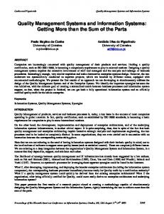
2 The Holonic Transport Case Study As depicted in the left-hand side of Figure below, we concerned with a part of a production system where specific work pieces (OBJECT) are processed by three different machines (Mx ) in a specific order. The transport of the work pieces is carried out by so called ”Holonic Transport Systems” (HTS) which are mobile robots. Machines have to initiate JOBs to execute transports of work pieces. These HTS have to be concurrent and self-organizing in a way that they locally decide by competing offers which transport job they execute. COMPONENT
Send transport job to all HTS
OBJECT
Entry buffer
HTS 1
HTS 2
HTS 3
available
available
available
HTS 4
HTS 5 Object
Machine 1
blocked
malfunction
HTS
5
HTS1
JOB
HTS1
HTS3 -
HTS2
5 4
HTS3 HTS4
time-limit for negotiation
Destination
OFFER
Object
DEMAND
SOURCE
DESTINATION
OBJECT
HTS5
HTS3 HTS4
Source
-
Holonic Transport System
HTS5
OBJECT Client
HTS2
HTS2
HTS4
CLOCK
Job(jid: nat)
5 Partner
Machine 3
BUFFER Machine(mid: nat)
Object(oid: nat)
start HTS1 Machine 2
Clock
MACHINE
HTS(hid: nat)
Calculate and broadcast offer
timeout
Cancel
HTS5 Exit buffer EXITBUFFER
Cancel
Approval
ENTRYBUFFER OUT
IN
Additionally, there are two buffers in that scenario. The first one (IN) provides “fresh” (entirely unprocessed) work pieces, whereas completely processed work pieces are delivered into the second one (OUT). Every machine consists of local entry and exit buffers which may store unprocessed/processed work pieces. Each time an object is removed from the local entry buffer or inserted into the local exit buffer, the machine calls for a HTS to deliver a new or remove a processed work piece. This way, we can distinguish between demand- (DEMAND) and offer-jobs (OFFER). A possible scenario is as like. A machine Mx generates a request and sends it together with a time-stamp via broadcast to all HTS. When a HTS receives the request, it first checks the current time and compares it with the requests time-stamp. If the elapsed time lies below a certain time-limit, the HTS may proceed the negotiation process. If a HTS is currently unable to perform the requested job for some reason it sends an unable message to all other HTS and aborts the negotiation. Otherwise the offer is calculated, sent to the other HTS and entered into an internal cost comparison table (CCT). Until the time-limit is reached, all HTS collect the offers of the other HTS and enter them into their CCT.
3
UML-Specification of the Case-study
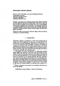
We model here the class-diagrams to cover the static aspects and state diagrams description to represent the dynamic part of the specification [3]. 3.1 Class and Object-Diagrams The right-hand side of the Figure above depicts the possible classes. The class COMPONENT, for instance, acts as a super-class for all active components (HTS, machines, buffers). HTS have to control the flow of work pieces in the scenario. The class JOB is an abstraction of a task a HTS must perform. Machines have local entry (SOURCE) and exit-buffers (DESTINATION). A BUFFER models an abstract super-class to insert, store, and release a (limited) number of work-pieces. Elements of class OBJECT model the work pieces. They are identified using the attribute oid. 3.2 State Diagrams With the behaviour state-diagram, different states of the objects in the scenario with state transition rules depicting the necessary preconditions and events are described. The Left-side of Figure 1 depicts the state diagram of the class HTS. By occurrence of the birth event start the HTS changes its state into ready. Receiving a job request from a machine in this state (receive job) changes the HTS into the state received J. In case a partner is required to perform the requested job, the HTS has to determine and contact all possible partners for the job (request Partner). Otherwise (e. g. if the HTS already carries a requested work piece) it may directly calculate the offer by the event calc Offer and make thereby a transition into the state calculated. In the contacted state, the HTS will have to wait until either all contacted partners have answered the request or a predefined time-limit (rlimit) has elapsed. The remaining HTS at this time may send the approval for the job (send Approval).
[Source.available>0] receive_RequestO
[rtimenlimit] send_Abort
[rtimerlimit] abort_ApprovedD
[ntime>nlimit] abort_Demand
[Source.available=0] send_JobD start
ready
demand [ntime0] next_Object
start
[Dest.free>0] receive_RequestD
requested [NOT partner_required] calc_Offer
[Source.available>0] process_Object
approved_D
calculated [exist_offer AND ntimenlimit] send_Approval [ntimebest_offer] abort
received_O
[Dest.free=0] send_JobO [my_offer=best_offer] wait_Offer
approved
processed
offer
[ntime>nlimit] abort_Offer
[ntimenlimit] abort_ApprovedO [rtime