UML Model Mappings for Platform Independent User Interface Design Tim Schattkowsky1 and Marc Lohmann2 1
C-LAB, Fürstenallee 11, 33102 Paderborn, Germany
[email protected] 2 University of Paderborn, Department of Computer Science, Warburger Str. 100, 33098 Paderborn, Germany
[email protected] Abstract. While model based design of platform independent application logic has already shown significant success, the design of platform independent user interfaces still needs further investigation. Nowadays, user interface design is usually platform specific or based on C-level cross-platform libraries. In this paper, we propose a MDA like design approach for user interfaces based on the transformation of UML models at different levels of abstraction. This enables platform independent design of user interfaces and a clear separation of UI and application logic design while enabling full use of native controls in the actual user interface implementation.
1 Introduction Today, user interface development is still dominated by platform-dependent GUI builders like those provided by the leading development environments. These tools are suitable for building prototypes and real UIs at a very low level of abstraction. Normally, they can only be used to design a user interface for one specific platform and one specific programming language. Usually a user interface designer who develops a user interface for an application has to understand the relationship between the different elements of his user interface, the implementation specific classes of the application and the specific characteristics of a target platform. Furthermore, lack of abstraction in UI design often forces large parts of the UI implementation in the responsibility of the software engineer rather than enabling the UI designer to work concurrently. Nowadays, these problems are getting even more important as contemporary applications are developed for different target platform. Modern information and communication systems have to present their UI on different devices with different capabilities. Thus, providing individual user interfaces for different target platforms becomes an increasing burden as the number of platforms as well as the size of the applications increases. UI Models can provide an abstraction from the detailed problems of the implementation technologies and specific platform characteristics and can allow user interface designers to focus on the conceptual tasks. In the software engineering community model-driven development has become very successful. Especially the diagrams of the industry standard UML (Unified Markup Language) [5] have become very sucJ.-M. Bruel (Ed.): MoDELS 2005 Workshops, LNCS 3844, pp. 201 – 209, 2006. © Springer-Verlag Berlin Heidelberg 2006
202
T. Schattkowsky and M. Lohmann
cessful and accompanying software development tools are available. Models are an established part of modern software development processes and thus a manual implementation of user interfaces becomes more and more undesirable. Furthermore, designing the interfaces on a higher abstraction level allows a clear separation of UI and application logic design. Thus, using models we can improve both productivity and software quality. The problem with using models for the development of user interfaces is that we still face the problem that we have to generate user interface implementations for different platforms. Again, we can find a solution for this problem in the field of software engineering. The OMG has proposed the Model Driven Architecture (MDA) [6] that allows for deriving code from stable models even if the underlying infrastructure shifts over time. The idea is to distinguish between platform-independent models (PIMs) that are refined into platform-specific models (PSMs) which carry annotations for the generation of platform-specific code. We propose an approach that adapts the MDA to the development of user interfaces. Our approach starts with the development of a platform independent model that describes the information to be displayed on a user interface. Designing the displayed information on such a high abstraction level allows for a complete separation of the user interface and application logic design. This platform independent model is refined at multiple levels to a platform specific model from which can be employed to generate an implementation for a specific target platform. The transformation steps between the different models are described by graph transformation rules. The remainder of this paper is organized as follows: The next section discusses related work before section 3 introduces our approach. Finally, section 4 closes with a conclusion and future work.
2 Related Work UI design has been subject to research for quite some time now. However, model based methods are largely discussed in the context of XML. The User Interface Markup Language (UIML) [1] is an XML language that aims at providing a meta language for the declarative description of UIs. UIML maps abstract UI elements to actual platform widgets and describes events on these elements. The mapping is based on identifiers with no additional semantics and must be done by the application. UIML does not provide a generic mapping approach from a single abstract specification to different platforms. Instead, it is not independent from the target platform and the event mapping mechanism is quite limited. This latter is addressed by [2] where a similar UI description is complemented by more sophisticated behavior specification. However, this is not comparable to the expressiveness of UML’s behavior models. The User interface eXtensible Markup Language (UsiXML) [4] addresses the need for more abstraction in UI design, but still in an XML context. However, it introduces the idea to create an abstract UI model based on a domain model that is later refined to a concrete UI model consisting of existing widgets. This model is the basis for generating the final UI implementation. The whole approach is based on XML and graph transformations [3]. It is not aligned with the UML or behavior modeling in general. However, the approach could produce UML compliant output and a UI design tool based on the approach is available [11].
UML Model Mappings for Platform Independent User Interface Design
203
Finally, [7] discusses UI modeling using the UML. Different levels of abstraction exist in the form of a fixed simple model for abstract UIs that are the foundation for manual refinement of the abstract model to the actual application model.
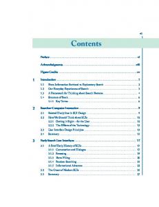
3 Design Approach Our approach is driven by the idea to allow for a complete separation of the UI and application logic design. As in MDA, our approach starts with the creation of a platform independent model. Before generating a platform specific UI implementation, the designer can configure the UI on multiple levels of PIMs, each independent of a target platform. From the most detailed PIM we can generate a platform specific UI implementation (see Fig. 1). Transformation rules between the different models facilitate tool support for our UI development approach.
Implementation Language
Code Generation Information Retrieval Model (IRM)
Concrete User Interface Model (CUIM) Transformation Rules
Platform Model (PM)
Information Retrieval Definition
View Composition Abstract User Interface Model (AUIM) Transformation Rules Information Model (IM)
Abstract UI Elements Model (AUIEM)
Platform Independent
View Composition Model (VCM)
Platform Dependent
Actual User Interface Implementation
Information Metamodel
Fig. 1. Platform Independent UI Design Flow
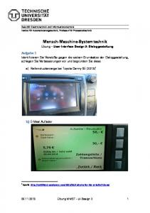
3.1 Information Model Our basic PIM is the Information Model (IM). This class diagram provides an abstract definition of the information and their logical dependencies that should be presented and modified through a UI. It is undistorted by technology information. Therefore, it allows business experts to ascertain much better than with a platform specific model and it provides an early starting point for user interface design.
204
T. Schattkowsky and M. Lohmann
Group
Folder + +
+
«editable» URI: String «editable» BasePath: String *
«editable» Name: String
«editable» *
*
*
*
Permissions + + + +
«editable» «editable» «editable» «editable»
Write: Boolean = false Read: Boolean = false List: Boolean = false Execute: Boolean = false
«editable»
«editable»
* «root» Serv er
User «editable»
+ * + + +
«editable» «editable» «editable» «editable»
Login: String Name: String = "" Password: String Description: String = "" 0..1
«editable» InternetAddress «editable»
+ +
«editable»
*
Hostname: String IPAddress: Integer [1..4 ordered]
* 1
ContentHandler
Port * «editable» * + +
«creatable» Number: Integer «creatable» UseSSL: Boolean
Body +
Length: Integer
«deletable» *
0..1 WebContentHandler +
Connection
«editable» DefaultDocumentName: String [0..* ordered] *
1 *
«editable» *
Message
MimeType +
«editable» FileExtensions: String [0..* ordered]
+ +
Number: Integer TimeStamp: DateTime
* Response + +
Code: Integer «editable» CloseConnection: Boolean 0..1
Request +
Method: String
1
Fig. 2. Web Server Configuration UI Example - Information Model
UML Model Mappings for Platform Independent User Interface Design
205
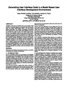
Figure 2 shows the IM of an administration interface of a simple Web server. The Web Server may have a ContentHandler at a certain Port to which a Connection can be made by a User to access the content of a Folder if he has the necessary Permissions according to his Group memberships. Furthermore, the pending Requests and Responses are represented. The associations and attributes in the IM are marked to indicate different kinds of data. Generally, the stereotypes and , are used to mark associations and attributes as only displayable or editable. Attributes marked may have their values altered at runtime while such associations may have links added and removed. If an association is marked as , links may only be removed in contrast to attributes, which may instead be marked as indicating that their value may only be set by the constructor, i.e., when creating a new instance. If no stereotype is provided for an attribute or association, is assumed. The data types used by the attributes in the IM are fixed and range from primitive types (e.g. Integer, Float) to complex types defined by classes. Operations may be defined to interface application logic that cannot be captured by the data model, e.g., to send explicit messages to the application aside from persistent data. The whole IM is a composition tree starting by a class whose only instance represents the whole systems. This enables inference of aggregations to automatically generate all levels of abstraction from the IM without the need for user interaction. However, usually this is not desirable and the UI designer wants to provide these decisions manually at each level of abstraction. 3.2 Abstract User Interface Model The PIM at the next level is the Abstract User Interface Model (AUIM). It includes some aspects of UI technology event though platform-specific details are absent. Essentially, the AUIM combines the data from the IM with abstract UI elements to access and manipulate that data. We have developed a metamodel –Abstract User Interface Elements Model (AUIEM)–that defines different UI elements at an abstract level in terms of related data sets and triggers. This Metamodel can be extended to project-specific needs by using the UML profiling mechanism. Figure 3 shows an excerpt from the AUIEM employed in our example. This excerpt defines the Choice UIElement for selecting one Item from a Set. Furthermore, it provides the necessary elements to employ the Choice to select an Instance of a Class or a Link from a Property. These elements are used in a set of graph transformation rules [8] that facilitate tool support for our approach. Each rule consists of a left hand side (subgraph of the IM) and a right hand side (subgraph of the respective AUIM to be created). In Fig. 4 an association is mapped to a set of UIElements for deleting and adding links on the association. The basic intuition is that every object or link, which is only present in the right hand side of the rule, is newly created and every object or link, which is present only in the left hand side of the rule, is being deleted. Objects or links which are present on both sides are unaffected by the rule.
206
T. Schattkowsky and M. Lohmann
«UIElement» Set
Type +type
+choices
1 +type
«UIElement» Choice
*
1
*
1 0..1 Class +class «UIElement» 1 * FilteredInstances {redefines type}
1
«UIElement» FilteredLinks
* +ownedAttribute
* Property
+property 1
*
+associationProperty
+chosen
«UIElement» UITrigger
«UIElement» Item
«UIElement» KillLinkTrigger
+link *
«UIElement» AddLinkTrigger
«UIElement» Link
1
+target *
0..1
«UIElement» Instance
1
Fig. 3. Excerpt from the AUIEM used for the Example Transformations
The application order of rules is not determined. Furthermore, different rules with the same left-hand side may exist to provide alternative UI elements for the same structure. The actual choice of the desired mappings is an interactive design decision that can be supported by tools. However, complete generation of the AUIM based on the rules is possible. This could be interesting in the context of an UI style defining the actual mappings to be applied.
UML Model Mappings for Platform Independent User Interface Design
L
207
R :Type
:Type +type
+type
:Property
:Class
+choices
:Property
+memberEnd
:Extension
:Association
+memberEnd :ExtensionEnd
:Property
«UIElement» :FilteredLinks
→
«UIElement»
«UIElement»
:AddLinkTrigger
:Choice
+target «UIElement»
+chosen
+chosen «UIElement»
+Link
«UIElement»
«UIElement»
:Choice
:KillLinkTrigger
+choices «UIElement» :FilteredInstances +class
:Stereotype
:Class
:Class
name = "editable"
Fig. 4. IM-AUIM Mapping Rule Example
3.3 View Composition Model The most detailed PIM is the View Composition Model (VCM). It partitions the AUIM into several overlapping and navigable Views. Each of these Views provides the scope of a Class instance for the contained UIElements. Thus, master-detail-like views can be implemented. Furthermore, navigation along Links can be defined. Finally, Views can be composed. Each contained view either inherits the scope from the containing view or has the scope provided by links selected in the containing View. A root View must be defined. Views enable the purposeful selection of different platform UI elements for the same UIElement depending on the overall context of a View while deriving the Concrete User Interface Model (CUIM) representing the actual platform dependent user interface.
208
T. Schattkowsky and M. Lohmann
3.4 Concrete User Interface Model The CUIM is defined by the Platform Model (PM), which contains a set of available native UI elements on the target platform. Like in the AUIEM, these elements are combined with the elements form the Information Metamodel. Thus, the translation between these models is based on the substitution of the UIElements from the AUIEM by native UI elements from the PM. The creation of the CUIM not only involves mapping the UIElements to actual UI controls (widgets) on the target platform, but also providing additional layout and decoration. A GUI builder tool should support the whole task where the designer may handpick individual mappings for UIElements. Transformation rules similar to the rules for the IM-AUIM transforamtion can be employed here. These rules map UIElements and their context to attributed and annotated instances of platform specific UI classes. The resulting CUIM has to be complemented by the Information Retrieval Model (IRM) describing how the data processed by the UI is actually accessed. The IRM is a behavioral UML model (e.g. an activity diagram) giving an operational description how to retrieve the IM elements from the actual implementation. Thus, the IRM functions as an abstraction layer between the UI and the application similar to database abstraction layers. However, the actual implementation of the IRM may vary and is not discussed here. To create an Actual User Interface Implementation, complete code generation takes place combining the IRM and CUIM information to a working platform dependent UI. Again, a set of transformation rules is used here.
4 Conclusion and Future Work In this paper, we have proposed a model-driven design approach for user interfaces based on the UML. This approach allows for concurrent development of UI and application logic by starting from a common platform independent information model. Furthermore, due to our code generation mechanisms we can support different target platforms from the same abstract model. The approach has been outlined and discussed on the context of a real world Web server administration interface example. We are currently implementing the results of the manual execution of our approach for this example. Future work will include a prototype implementation in the context of our work in the fields of executable models [10] and concurrent software components [9].
References 1. Abrams, M., Phanouriou, C., Batongbacal, A. L., Williams, S. M., Shuster, J. E.: UIML: an appliance-independent xml user interface language. In Computer Networks 31, Elsevier Science, 1999 2. Bleul, S., Schäfer, R., Müller, W.: Multimodal Dialog Description for Mobile Devices. In Proc. Workshop on XML-based User Interface Description Languages at AVI 2004, 2004.
UML Model Mappings for Platform Independent User Interface Design
209
3. Limbourg, Q., Vanderdonckt, J.: Addressing the Mapping Problem in User Interface Design with UsiXML. In Proc. of 3rd Int. Workshop on Task Models and Diagrams for user interface design TAMODIA’2004, ACM Press, New York, 2004. 4. Limbourg, Q., Vanderdonckt, J., Michotte, B., Bouillon, L., Lopez-Jaquero, V.: UsiXML: a Language Supporting Multi-Path Development of User Interfaces. In Proc. EHCIDSVIS'2004, 2004. 5. Object Management Group, The: Unified Modeling Language: Infrastructure. OMG ad/2004-10-02, 2004. 6. Object Management Group, The: Model Driven Architecture (MDA). OMG ormsc/200107-01, 2001. 7. Pinheiro da Silva, P., Paton, N.: User Interface Modelling with UML. In Proc. of the 10th European-Japanese Conference on Information Modelling and Knowledge Representation, 2000. 8. Rozenberg, G. et al (eds.): Handbook of Graph Grammars and Computing by Graph Transformation, Vol. 1. World Scientific, Singapore, 1997 9. Schattkowsky, T., Förster, A: A generic Component Framework for High Performance Locally Concurrent Computing based on UML 2.0 Activities. In Proc. 12th Annual IEEE International Conference and Workshop on the Engineering of Computer Based Systems (ECBS), 2005. 10. Schattkowsky, T. Müller, W.: Model-Based Design of Embedded Systems. In Proc. 7th IEEE International Symposium on Object-oriented Real-time distributed Computing (ISORC), 2004. 11. Vanderdonckt, J.: A MDA-Compliant Environment for Developing User Interfaces of Information Systems. In Proc. of 17th Conf. on Advanced Information Systems Engineering CAiSE'05 (Porto, 13-17 June 2005), O. Pastor & J. Falcão e Cunha (eds.), Lecture Notes in Computer Science, Vol. 3520, Springer-Verlag, Berlin, 2005.