design and components architecture of a Ubicomp system and application to ... graphical user interface and 2) to load uMove enabled services for Android ...
Department of Informatics University of Fribourg (Switzerland)
uMove: A wholistic framework to design and implement ubiquitous computing systems supporting user’s activity and situation
THESIS
Submitted to the Faculty of Science, University of Fribourg (Switzerland) to obtain the degree of Doctor Scientiarum Informaticarum
Pascal Bruegger from Graben BE (Switzerland)
Thesis N◦ 1711 UniPrint, Fribourg 2011
Accepted by the Faculty of Science of the University of Fribourg following the proposal of: - Prof. Ulrich Ulthes-Nitsche, University of Fribourg (Jury President) - Prof. B´eat Hirsbrunner, University of Fribourg, Switzerland (Thesis Director) - Dr. Denis Lalanne, University of Fribourg, Switzerland (Expert) - Prof. Alan Dix, Lancaster university, UK (External expert) - Prof. Peter Kropf, University of Neuchˆatel, Switzerland (External expert)
Fribourg, 6 June 2011
Thesis Director
Faculty Dean
Prof. B´eat Hirsbrunner
Prof. Rolf Ingold
2011 by Pascal Bruegger ©All Rights Reserved
Acknowledgments A PhD thesis is long term process full of particular moments which are sometimes emotionally intense, sometimes desperately frustrating but also very motivating to continue. At the end, the result is an extraordinary experience from a personal and a scientific point of view. This type of challenge would not have been possible without the support of valuable people who guided and advised me during this research. My deepest gratitude goes to my supervisor, Prof. B´eat Hirsbrunner, who gave me the opportunity to study in the Department of Informatics of the University of Fribourg and trusted me for this thesis. I would also like to thank my PhD committee for their expertise and the Swiss National Science Foundation (SFNS) for the financial support during the last four years. I would like to sincerely thank my two colleagues, Dr. Agnes Lisowska Masson and Dr. Apostolos Malatras for their constructive comments and advise during the writing of the thesis. I take this opportunity to also thank also all my colleagues in the department, Elisabeth Br¨ ugger, Silviane Pilloud, Bruno Dumas, Denis Lalanne, Maurizio Rigamonti, Florian Ev´equoz, Amos Brocco, Fulvio Frapolli, Muriel Bowie, Oliver Schmid, Momouh Khadraoui and Nicolas Juillerat for all enjoyable moments we spent together on different occasions. I wish to also thank Benjamin Hadorn, Samuel Vonlanthen, Adriana Wilde and Sa¨ıd Mechkour for their precious collaboration on this research and their contribution in different projects. Of course, nothing would have been possible without my beloved family, my wife Prisca, my son Samuel and my mother Yolande. They were always supporting me, especially in stressful moments and I’m deeply grateful and proud to be loved so much.
A chapter ends, a new one starts.
i
ii
Abstract This thesis presents a framework that offers tools for the design and the implementation of Ubiquitous computing systems supporting user motions, activities and situations. With the rapid development of context-aware mobile computing and sensor-based interaction, many new challenges come up, three of which are particularly addressed in this thesis. The first is the need for wholistic tools to develop Ubiquitous computing infrastructures. The second concerns smart applications allowing users to benefit from the distributed computing power in their environment, and the third is the integration of enriched human-computer interaction using motions, activity and situation provided by the increasing sensing capabilities of the user environment or mobile devices. We propose the uMove framework, a comprehensive solution which allows to design and develop Ubicomp systems representing different kinds of physical or virtual environments based on a systemic approach. uMove proposes both theoretical foundations and implementation tools and is divided into three specific facets. The first facet is the conceptual model describing a Ubiquitous computing system made of entities and observers within their physical or logical environment. The second facet is a system architecture which offers designers and developers the tools to theoretically define a logical system, including the types of contexts taken into consideration. The third facet is development tools that allow programmers to implement their systems, sensors, applications and services. The uMove framework is evaluated and validated in an interactive manner through four projects. Keywords: Ubiquitous computing, pervasive computing, context-aware computing, mobile computing, HCI, middleware.
iii
iv
R´ esum´ e Cette th`ese pr´esente un ensemble d’outils (un framework ) qui permettent la d´efinition, la cr´eation et la r´ealisation de syst`emes informatiques ubiquitaires pouvant int´egrer la prise en charge des activit´es des utilisateurs ainsi que de la d´etection de leur situation. Avec le rapide d´eveloppement de l’informatique int´egrant les contextes des utilisateurs ainsi que l’informatique mobile, de nouveaux d´efis sont apparus et parmi ceux-ci, trois d’entre eux sont adress´es dans cette th`ese. Le premier est le besoin d’un ensemble d’outils permettant le d´eveloppement de syst`emes ubiquitaires partant de leur d´efinition th´eorique jusqu’`a leur r´ealisation. Le deuxi`eme d´efi consiste ` a d´evelopper des applications intelligentes qui int´egrantent les nouvelles technologies telles que les senseurs et l’acc`es `a des syst`emes informatiques r´epartis. Le troisi`eme d´efi est l’int´egration d’interactions homme-machine enrichies par la prise en compte des mouvements, des activit´es et situations des utilisateurs ceci par le biais de senseurs de plus en plus pr´esents dans nos environnements et sur les dispositifs informatiques mobiles. Dans cette th`ese, nous d´ecrivons uMove, un ensemble d’outils permettant la d´efinition et le d´eveloppement de syst`eme ubiquitaire repr´esentant diff´erentes sortes d’environnements physiques ou logiques. uMove comporte trois facettes qui d´ecrivent les concepts fondamentaux ainsi que les outils logiciels n´ecessaires `a leur d´eveloppement. La premi`ere facette est consacr´ee `a la d´efinition du mod`ele conceptuel d´ecrivant des syst`emes ubiquitaires compos´es d’entit´es et d’observateurs et ceci en utilisant une approche syst´emique. La deuxi`eme facette pr´esente une architecture qui permet aux concepteurs et d´eveloppeurs de formaliser leurs syst`emes. La troisi`eme facette d´ecrit les outils logiciels qui permettront d’impl´ementer les projets d´efinis de mani`ere syst´emique et en respectant l’architecture uMove. Finalement, uMove est ´evalu´e et son mod`ele valid´e `a travers quatre projets qui ont ´et´e impl´ement´es avec l’ensemble de ces outils. Mots-cl´ es: Informatique ubiquitaire, informatique pervasive, informatique contextuelle, informatique mobile, interaction homme-machine, plateforme de d´eveloppement.
v
vi
Acronyms ABC ACD AI API AT GIS GPS GST GUI HCI IDE iHCI JSON KUI LCD MVC OWL PDA SQL SUI TUI Ubicomp UCD UML URL UUI WIMP XML
: : : : : : : : : : : : : : : : : : : : : : : : : : : :
Activity-based computing Activity-centered Design Artificial Intelligence Application Programming Interface Activity Theory Geographic Information Systems Global Positioning System General System Theory Graphical User Interface Human-Computer Interaction Integrated Development Environment implicit Human-Computer Interaction JavaScript Object Notation Kinetic User Interface Liquid Crystal Display Model-View-Controler Web Ontology Language Personal Digital Assistant Structured Query Language Surface User Interface Tangible User Interface Ubiquitous Computing User Centered Design Unified Modelling Language Uniform Resource Locator Ubicomp User Interface Windows, Icon, Menu, Pointer Extensible Markup Language
vii
viii
Contents Acknowledgments
i
Abstract
iii
R´ esum´ e
v
Acronyms
vii
1 Introduction 1.1 Research challenges . . . . . . . . . . . . . . . . . . . . . . . 1.1.1 Tools for developing and deploying Ubicomp systems 1.1.2 Smart and adaptive applications and services . . . . 1.1.3 User interaction . . . . . . . . . . . . . . . . . . . . 1.2 Goals . . . . . . . . . . . . . . . . . . . . . . . . . . . . . . 1.3 Focus of the thesis . . . . . . . . . . . . . . . . . . . . . . . 1.4 Contribution . . . . . . . . . . . . . . . . . . . . . . . . . . 1.4.1 System modelling . . . . . . . . . . . . . . . . . . . . 1.4.2 System architecture . . . . . . . . . . . . . . . . . . 1.4.3 Implementation tools . . . . . . . . . . . . . . . . . . 1.4.4 Validation scenario and applications . . . . . . . . . 1.5 Outline of the thesis . . . . . . . . . . . . . . . . . . . . . . 2 Background and related work 2.1 Ubiquitous and pervasive computing . . . . . . . . . . . 2.2 Ubiquitous computing: definition of the paradigm . . . 2.2.1 Ubiquitous computing is not nomadic computing 2.2.2 From Weiser’s vision to now: where do we stand? 2.3 Context-aware computing . . . . . . . . . . . . . . . . . 2.3.1 Context: concept and definitions . . . . . . . . . 2.3.2 Context-aware architectures and middlewares . . 2.3.3 Context-aware applications . . . . . . . . . . . . 2.3.4 Sensing contexts . . . . . . . . . . . . . . . . . . ix
. . . . . . . . .
. . . . . . . . .
. . . . . . . . . . . .
. . . . . . . . .
. . . . . . . . . . . .
. . . . . . . . .
. . . . . . . . . . . .
. . . . . . . . .
. . . . . . . . . . . .
. . . . . . . . .
. . . . . . . . . . . .
. . . . . . . . .
. . . . . . . . . . . .
. . . . . . . . .
. . . . . . . . . . . .
. . . . . . . . .
. . . . . . . . . . . .
. . . . . . . . .
. . . . . . . . . . . .
. . . . . . . . .
. . . . . . . . . . . .
1 2 3 3 4 4 5 6 6 6 6 7 7
. . . . . . . . .
9 9 10 11 11 13 13 16 18 20
2.4
2.5
2.6
2.7
2.3.5
Ambient intelligence and smart environments . . . . . . . . . . . . . .
21
2.3.6
Discussion . . . . . . . . . . . . . . . . . . . . . . . . . . . . . . . . . .
22
Human-computer interaction in ubiquitous computing . . . . . . . . . . . . .
23
2.4.1
Post-desktop paradigm of interaction . . . . . . . . . . . . . . . . . . .
23
2.4.2
From GUI to UUI: a new opportunity for human-ubicomp system interaction . . . . . . . . . . . . . . . . . . . . . . . . . . . . . . . . . .
24
Activity-based computing . . . . . . . . . . . . . . . . . . . . . . . . . . . . .
26
2.5.1
Activity Theory: concepts and applications . . . . . . . . . . . . . . .
27
2.5.2
Models and tools . . . . . . . . . . . . . . . . . . . . . . . . . . . . . .
27
Reasoning on situation: an evolution of activity-based computing . . . . . . .
30
2.6.1
Definition of situation . . . . . . . . . . . . . . . . . . . . . . . . . . .
30
2.6.2
Situation theory . . . . . . . . . . . . . . . . . . . . . . . . . . . . . .
31
2.6.3
Application of situation theory . . . . . . . . . . . . . . . . . . . . . .
31
Summary . . . . . . . . . . . . . . . . . . . . . . . . . . . . . . . . . . . . . .
32
3 Conceptual model
35
3.1
System modelling . . . . . . . . . . . . . . . . . . . . . . . . . . . . . . . . . .
36
3.2
General System Theory . . . . . . . . . . . . . . . . . . . . . . . . . . . . . .
38
3.3
System . . . . . . . . . . . . . . . . . . . . . . . . . . . . . . . . . . . . . . . .
38
3.4
uMove system . . . . . . . . . . . . . . . . . . . . . . . . . . . . . . . . . . . .
39
3.4.1
Environment and entities . . . . . . . . . . . . . . . . . . . . . . . . .
40
3.4.2
Observation . . . . . . . . . . . . . . . . . . . . . . . . . . . . . . . . .
48
Kinetic dimension . . . . . . . . . . . . . . . . . . . . . . . . . . . . . . . . .
51
3.5.1
Separation between activity and situation . . . . . . . . . . . . . . . .
52
3.5.2
Motion . . . . . . . . . . . . . . . . . . . . . . . . . . . . . . . . . . .
53
3.5.3
Activities . . . . . . . . . . . . . . . . . . . . . . . . . . . . . . . . . .
54
3.5.4
Contexts
. . . . . . . . . . . . . . . . . . . . . . . . . . . . . . . . . .
54
3.5.5
Situations . . . . . . . . . . . . . . . . . . . . . . . . . . . . . . . . . .
55
Summary . . . . . . . . . . . . . . . . . . . . . . . . . . . . . . . . . . . . . .
57
3.5
3.6
4 System Architecture, Design and Evaluation 4.1
59
uMove middleware: a multilayer architecture . . . . . . . . . . . . . . . . . .
60
4.1.1
Sensor layer . . . . . . . . . . . . . . . . . . . . . . . . . . . . . . . . .
61
4.1.2
Entity layer . . . . . . . . . . . . . . . . . . . . . . . . . . . . . . . . .
63
4.1.3
Observation layer . . . . . . . . . . . . . . . . . . . . . . . . . . . . . .
64
4.1.4
Message processors . . . . . . . . . . . . . . . . . . . . . . . . . . . . .
66
4.1.5
Activity and situation manager . . . . . . . . . . . . . . . . . . . . . .
67
4.2
Mobile uMove system . . . . . . . . . . . . . . . . . . . . . . . . . . . . . . .
68
4.3
Coordination and communication in uMove . . . . . . . . . . . . . . . . . . .
68
4.4
Applications and services . . . . . . . . . . . . . . . . . . . . . . . . . . . . .
69
x
4.5
4.6
IWaT: methods and tools to test the uMove system . . . . . . . . . . . . . . .
70
4.5.1
Using IWaT with uMove . . . . . . . . . . . . . . . . . . . . . . . . . .
71
4.5.2
How it works . . . . . . . . . . . . . . . . . . . . . . . . . . . . . . . .
72
4.5.3
Advantages and drawbacks of using IWaT
. . . . . . . . . . . . . . .
73
Summary . . . . . . . . . . . . . . . . . . . . . . . . . . . . . . . . . . . . . .
74
5 Implementation tools 5.1
77
uMove API . . . . . . . . . . . . . . . . . . . . . . . . . . . . . . . . . . . . .
78
5.1.1
UMoveSystem
. . . . . . . . . . . . . . . . . . . . . . . . . . . . . . .
78
5.1.2
Message processor . . . . . . . . . . . . . . . . . . . . . . . . . . . . .
81
5.1.3
Activity and situation managers . . . . . . . . . . . . . . . . . . . . .
82
5.1.4
Relation manager . . . . . . . . . . . . . . . . . . . . . . . . . . . . . .
82
Coordination and communication . . . . . . . . . . . . . . . . . . . . . . . . .
82
5.2.1
Coordination manager . . . . . . . . . . . . . . . . . . . . . . . . . . .
83
5.2.2
Communication . . . . . . . . . . . . . . . . . . . . . . . . . . . . . . .
84
5.2.3
Services: definition and monitoring . . . . . . . . . . . . . . . . . . . .
85
Mobile monitoring . . . . . . . . . . . . . . . . . . . . . . . . . . . . . . . . .
86
5.3.1
Monitoring mobile devices . . . . . . . . . . . . . . . . . . . . . . . . .
87
5.3.2
Services list update . . . . . . . . . . . . . . . . . . . . . . . . . . . . .
87
5.3.3
System service . . . . . . . . . . . . . . . . . . . . . . . . . . . . . . .
87
5.3.4
Public services . . . . . . . . . . . . . . . . . . . . . . . . . . . . . . .
87
Mobile uMove system . . . . . . . . . . . . . . . . . . . . . . . . . . . . . . .
89
5.4.1
Type of service: local versus global . . . . . . . . . . . . . . . . . . . .
90
5.4.2
Mobile uMove as a service manager . . . . . . . . . . . . . . . . . . .
90
5.4.3
Smart environment finder . . . . . . . . . . . . . . . . . . . . . . . . .
91
5.4.4
Mobile service manager . . . . . . . . . . . . . . . . . . . . . . . . . .
91
5.5
uMove-enabled applications . . . . . . . . . . . . . . . . . . . . . . . . . . . .
92
5.6
uMove System Editor . . . . . . . . . . . . . . . . . . . . . . . . . . . . . . .
93
5.6.1
Entity management . . . . . . . . . . . . . . . . . . . . . . . . . . . .
95
5.6.2
Saving and loading a system configuration . . . . . . . . . . . . . . . .
95
5.6.3
System monitoring
. . . . . . . . . . . . . . . . . . . . . . . . . . . .
96
5.6.4
Application and service loader . . . . . . . . . . . . . . . . . . . . . .
96
Summary . . . . . . . . . . . . . . . . . . . . . . . . . . . . . . . . . . . . . .
98
5.2
5.3
5.4
5.7
6 Prototypes and validation
99
6.1
Methods of evaluation and validation . . . . . . . . . . . . . . . . . . . . . . .
99
6.2
Smart Heating System . . . . . . . . . . . . . . . . . . . . . . . . . . . . . . . 101 6.2.1
User’s activities and contexts . . . . . . . . . . . . . . . . . . . . . . . 101
6.2.2
Software architecture . . . . . . . . . . . . . . . . . . . . . . . . . . . . 101
6.2.3
Hardware . . . . . . . . . . . . . . . . . . . . . . . . . . . . . . . . . . 102 xi
6.3
6.4
6.5
6.6
Robin project: how Ubicomp technologies can help firefighters . 6.3.1 Context of the project . . . . . . . . . . . . . . . . . . . 6.3.2 Gathering contextual information . . . . . . . . . . . . . 6.3.3 Robin architecture . . . . . . . . . . . . . . . . . . . . . 6.3.4 IWaT session . . . . . . . . . . . . . . . . . . . . . . . . 6.3.5 Session results . . . . . . . . . . . . . . . . . . . . . . . 6.3.6 The prototype . . . . . . . . . . . . . . . . . . . . . . . 6.3.7 Global results . . . . . . . . . . . . . . . . . . . . . . . . EMS project: Elderly Monitoring System . . . . . . . . . . . . 6.4.1 General requirement . . . . . . . . . . . . . . . . . . . . 6.4.2 Setup . . . . . . . . . . . . . . . . . . . . . . . . . . . . 6.4.3 Server application . . . . . . . . . . . . . . . . . . . . . 6.4.4 Mobile application . . . . . . . . . . . . . . . . . . . . . 6.4.5 Evaluation of uMove . . . . . . . . . . . . . . . . . . . . SMSService: a concrete use case of a uMove service . . . . . . . 6.5.1 Server part . . . . . . . . . . . . . . . . . . . . . . . . . 6.5.2 Client part . . . . . . . . . . . . . . . . . . . . . . . . . Summary . . . . . . . . . . . . . . . . . . . . . . . . . . . . . .
7 Conclusions and Perspectives 7.1 Thesis orientation . . . . . . . . . . . . . . . . . . 7.2 uMove framework: a promising wholistic tool . . . 7.2.1 Conceptual model . . . . . . . . . . . . . . 7.2.2 uMove system architecture . . . . . . . . . 7.2.3 Integration of a mobile server-based uMove 7.2.4 Implementation tools . . . . . . . . . . . . . 7.2.5 Validation projects . . . . . . . . . . . . . . 7.3 Perspectives . . . . . . . . . . . . . . . . . . . . . . 7.3.1 uMove API . . . . . . . . . . . . . . . . . . 7.3.2 uMove System Editor . . . . . . . . . . . . 7.3.3 Mobile uMove middleware . . . . . . . . . . 7.3.4 Development of services . . . . . . . . . . . 7.3.5 Activity and situation management . . . . . 7.3.6 Full evaluation . . . . . . . . . . . . . . . . 7.4 Epilogue . . . . . . . . . . . . . . . . . . . . . . . .
. . . . . . . . . . . . . . .
. . . . . . . . . . . . . . .
. . . . . . . . . . . . . . .
. . . . . . . . . . . . . . .
. . . . . . . . . . . . . . .
. . . . . . . . . . . . . . .
. . . . . . . . . . . . . . .
. . . . . . . . . . . . . . . . . .
. . . . . . . . . . . . . . .
. . . . . . . . . . . . . . . . . .
. . . . . . . . . . . . . . .
. . . . . . . . . . . . . . . . . .
. . . . . . . . . . . . . . .
. . . . . . . . . . . . . . . . . .
. . . . . . . . . . . . . . .
. . . . . . . . . . . . . . . . . .
. . . . . . . . . . . . . . .
. . . . . . . . . . . . . . . . . .
. . . . . . . . . . . . . . .
. . . . . . . . . . . . . . . . . .
. . . . . . . . . . . . . . .
. . . . . . . . . . . . . . . . . .
103 103 104 104 105 106 106 111 111 112 112 113 114 114 115 116 117 118
. . . . . . . . . . . . . . .
121 122 122 123 124 125 125 126 127 127 128 129 129 130 130 131
Bibliography
135
Terms and definitions
147
List of Tables
148 xii
List of Figures
149
List of Listings
153
Curriculum Vitae
157
xiii
Chapter 1
Introduction Contents 1.1
Research challenges . . . . . . . . . . . . . . . . . . . . . . . . . . .
2
1.2
Goals . . . . . . . . . . . . . . . . . . . . . . . . . . . . . . . . . . . .
4
1.3
Focus of the thesis . . . . . . . . . . . . . . . . . . . . . . . . . . . .
5
1.4
Contribution . . . . . . . . . . . . . . . . . . . . . . . . . . . . . . .
6
1.5
Outline of the thesis . . . . . . . . . . . . . . . . . . . . . . . . . . .
7
Ubiquitous Computing (Ubicomp) is radically changing our everyday activities by bringing computing power into our living environment. Computers are more and more distributed throughout the environment and tend to disappear into everyday objects. They are enhanced by technologies able to sense the environment, communicate and provide information to a user any time and any where. In the late 80’s, Mark Weiser put forward the idea of invisible computing. He predicted that in the near future, we would see a shift in computer systems: from the concept of ”one computer one user” we would move to ”one user many computers” [Weiser, 1991]. That the desktop computer would be replaced by many specialised computing devices scattered in the space around us, able to sense our environment and provide help in our everyday lives. As Weiser wrote in the fundamental article in Scientific American: ”The most profound technologies are those that disappear. They weave themselves into the fabric of everyday life until they are indistinguishable from it” Weiser’s vision of Ubiquitous computing is partly becoming a reality and there exist plenty of Ubicomp applications, components and infrastructures such as GPS navigation in cars, electronic agendas synchronised with computers, or mobile communication systems including laptops, netbooks, netpads, mobile and smart phones and PDAs. During the last decades, we have seen a shift from the traditional desktop computer toward heterogeneous 1
2
Chapter 1:
Introduction
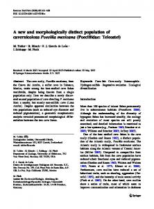
technologies from small and mobile interconnected devices to large wall-sized displays as well as car embedded computing systems. These technological examples show that Ubiquitous Computing has evolved in the last twenty years. However, many questions about Ubicomp remain open: What really evolved? Concepts or technologies? Where do we stand with Weiser’s concept of invisible computing? [Bell and Dourish, 2007, Rogers, 2006] Have we fundamentally changed our way of interacting with computing systems? What research challenges are still relevant after thirty years of Ubicomp development? As mentioned by Schmidt in [Schmidt, 2002, ch. 2], research in the domain of pervasive or ubiquitous computing is diverse and this field is still not properly defined. Ubicomp includes aspects of Distributed Systems, Mobile Computing, Software Architecture, HumanComputer Interaction (HCI), and Artificial Intelligence (AI) as well as engineering as it deals with hardware such as sensors (Fig. 1.1).
Figure 1.1: Panel of the different computing domains that are included in the concept of Ubicomp
1.1
Research challenges
Because it is a multidisciplinary domain, Ubicomp has no formal nor unique definition and includes several research approaches. Many challenges are addressed in Ubicomp and among them, there are three aspects which we found particularly important to explore: 1) wholistic tools to develop Ubicomp infrastructures, 2) smart applications allowing users to benefit from the distributed computing power in their environment and 3) the integration of enriched human-computer interactions using motions, activity and situation provided by the increasing sensing capability of the user environment or mobile devices.
1.1:
1.1.1
Research challenges
3
Tools for developing and deploying Ubicomp systems
There are at least two problems in the development of Ubicomp systems. The first one is the generic modelling tools to properly define complete systems (from the sensors to the application). Projects such as CAMUS [Hung et al., 2004] or MUSIC [Reichle et al., 2008] propose frameworks for context modelling and ontology-based representation. They are predominately oriented towards functional aspects of the system and, even if they adopt a user-centered and context-aware approach, they do not necessarily propose the tools for designing the system including users, environments (places) and relations between entities which constitute the system. The second problem is the integration of heterogeneous hardware and software technologies in order make them work together and provide coordinated services to users. Due to the distributed and dynamic nature of Ubicomp systems, this challenge includes dynamic coordination and communication of devices and applications active in the user environment as well as service discovery and security [Coulouris et al., 2001, p.6-7] as proposed in the GAIA project [Roman et al., 2002] or HP’s CoolTown project [Kindberg and Barton, 2001]. There is a strong need for standardised platforms, frameworks and middlewares allowing to develop infrastructure and connect several kinds of sensors and computational devices, and to run contextualised applications and services. There exist different tools and environments to support the development of systems. Among them, are Georgia Tech’s Context Toolkit [Dey et al., 2001], MIT’s Oxygen1 , Carnegie Mellon’s Aura [Garlan et al., 2002] and the ActiveCampus [Griswold et al., 2003]. These projects focus on the implementation of systems integrating different types of interacting physical devices including smart phones, sensors and large scale public displays. The challenge consists of developing integrated tools including three aspects of the development process which are 1) the definition of the Ubicomp system (the model), 2) the evaluation of the model and its validation and 3) the implementation of the system modelling the user’s environment and applications.
1.1.2
Smart and adaptive applications and services
Ubicomp system interfaces should adapt their behaviour according to the situation, be aware of the context and not require much user attention. Recently, we have witnessed an increasing number of mobile devices such as smartphones and academic applications such as CyberGuide [Abowd et al., 1997], GUIDE [Cheverst et al., 2000] or UbiCicero [Ghiani et al., 2008] which use information about user contexts gathered through sensors in order to do the right things at the right time. There are also commercial applications such as Google AdSense2 which contextualise information and services according to a user’s location. Context-awareness and 1 2
http://oxygen.lcs.mit.edu/Overview.html https://www.google.com/adsense/
4
Chapter 1:
Introduction
context-aware systems have been extensively explored and many articles have been written about since the ’90s [Shilit and Theimer, 1994]. Generally, context-aware applications use contexts such as location, time, temperature, light intensity or, nowadays, accelerometers to trigger events. For example, in some smartphones, the silent mode can be enabled when they are placed in a given position or, in the best case, in a given location. In the first case, the result is obtained by direct user interaction with his device (turning the phone face down) and in the second through the location context. However, we believe that applications could be smarter if more user’s characteristics such as motions and activity were combined with other contexts.
1.1.3
User interaction
As a new paradigm, Ubicomp has also changed the way the user interacts with computing devices. Computers systems and devices offer different modes of interaction with sometimes only a minimal portion of the ordinary desktop interface (screen, keyboard, mouse). Also, the growing number of devices surrounding users no longer allows each of them to capture the user’s full attention. Following the idea of ”computer everywhere”, also called Everyware by Greenfield [Greenfield, 2006], Weiser proposed the concept of calm technology or computing [Weiser and Brown, 1996] which suggests that users should not be overloaded by information and that some of it can be put at the periphery, leaving user attention for the main user activity. For Weiser, ”A calm technology will move easily from the periphery of our attention, to the center, and back”. This also influences the mode of interaction with computer systems and creates a need for more implicit interaction rather than the current explicit one. Consequently, the usercomputer interfaces and, more importantly, the interaction mode must be adequately designed in order to reach this goal. With the development and miniaturisation of sensors, we tend to a more sensor-based and implicit interaction [Dix, 2002] and therefore move from the commonly used Graphical User Interface (GUI) toward a Ubicomp User Interface (UUI) [Krumm, 2010]. In order to reach this goal in the next generation of Ubicomp and context-aware systems, there is a need to enrich the contexts by taking into consideration user behaviour and intention. There is already an increasing interest in the integration of new parameters such as user motions, gestures activities and situation in order to make applications smarter and more adaptive. As pointed out by Sparacino in [Sparacino, 2005]: ”[...] computation and sensing are moving from computers and devices into the environment itself. The space around us is instrumented with sensors and displays, and this tends to reflect a widespread need to blend together the information space with our physical space”.
1.2:
1.2
Goals
5
Goals
The first goal of this research was to explore an interaction paradigm we called Kinetic User Interface (KUI) which includes user activity and situation as input modalities for contextaware systems, and to propose a platform to support this paradigm. However, before reaching this goal, we found two aspects which need to be primarily addressed as they are often missing in the Ubicomp development process. The first one is the lack of tools for the modelling of (user’s) environments in which the Ubicomp systems are set. In many projects or research, the proposed solutions include all the components from the sensors to the application in one concept instead of clearly separating the environment, the technologies which allow to gather information about the environment and the applications (which can be heterogeneous and specialised). The second aspect concerns the development of integrated tools that designers and programmers can use to develop systems which allow a seamless integration of user activity and situation.
1.3
Focus of the thesis
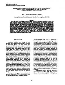
In this thesis, we focus on two particular aspects. The first aspect concerns the development of a comprehensive framework to design and develop Ubicomp systems representing different kinds of physical or virtual environments. This framework, called uMove, proposes both theoretical foundations and implementation tools, and is divided in three specific facets. The first facet is the conceptual model which describes a Ubicomp system made of entities and observers within their physical or logical environment (Fig. 1.2). The second facet proposes the system architecture which allows designers and developers to theoretically define a logical system, including the types of contexts taken into consideration. The third facet is the development tools allowing programmers to implement their system and applications.
Figure 1.2: The three facets of the uMove development framework: semantic modelling, architecture of the system and the implementation.
The second aspect focuses on the way to integrate, within the framework, the management
6
Chapter 1:
Introduction
of the kinetic properties (motions and activity) of entities in order to enrich the interaction with context-aware computing systems and to allow the development of applications and services which adapt their behaviours to the situation of the moving entity.
1.4
Contribution
The main contribution of this thesis is the creation of a comprehensive development framework for Ubicomp systems and context-aware applications. The specific contributions are: The definition of a semantic model for the modelling of physical or virtual environments (A city, a university campus, computer games, web sites) into logical representations. The definition of an architecture model for Ubicomp systems and a set of tools to support designers in the validation of their model before the implementation phase. A set of programming tools for the implementation of systems and applications. Proof-of-concept applications integrating the activity, motion and situation implemented with the framework.
1.4.1
System modelling
The approach chosen for our model of environment follows the systemic concepts and the semantic model is based on Von Bertalanffy’s General System Theory (GST) [von Bertalanffy, 1969]. Von Bertalanffy was a biologist who developed a theory generalising the definitions of systems used in specific scientific disciplines such as physics, (bio-)chemistry, mathematics, biology, economics or social sciences. A modelled environment becomes a system, in the systemic sense. A system models the physical or virtual world where objects (entities), possibly living things capable of motion, interact naturally with their environment and are observed by agents (observers).
1.4.2
System architecture
Based on the semantic model, we propose an architecture which allows to define different layers of abstraction including a system made of interacting entities, the sensors gathering the different entity contexts, the system observation and the context-aware applications which handle the events received by the sensors. We also present a methodology to evaluate the design and components architecture of a Ubicomp system and application to ensure that the various algorithms, strategies, inferences (of activities or context) and sensors operate together smoothly, satisfy user requirements, take into account technical and infrastructure limitations and form a coherent and comprehensive system.
1.5:
1.4.3
Outline of the thesis
7
Implementation tools
Once modelled and validated, a system can be implemented with a set of Java-based programming tools. We developed APIs that offer the necessary classes and methods to build the middleware on which the system will run. These APIs allow to connect sensors and context-aware applications which interact with the entities, and they offer functionality for the monitoring and integration of mobile devices running on the Android platform. We also propose a graphical user interface which can instantiate and monitor a system and dynamically load services for mobile devices.
1.4.4
Validation scenario and applications
We propose a set of validation projects that use the uMove framework, implement the concepts of systems and test the capability of the proposed concepts to adequately address the research goals. Through these projects, we also experiment with the concept of Kinetic User Interface (KUI) using scenarios which imply a mode of interaction where location and motion tracking, including user activity, can be used as first order input modalities to a Ubicomp system. The goal of a KUI is to allow users to interact with Ubicomp systems in a more implicit way using their kinetic properties to trigger events at the level of applications. The first project, called Robin, focuses on the observation of a rescue team helped by a semi-autonomous robot. The robot is sent ahead of the team and gathers contextual information in a building (in case of fire for instance) to send back to the server for situation analysis and activity recommendation or possibly alarms. The second project provides a smart environment for a nursing home. It focuses on the activity tracking of elderly persons who are still independent but monitored by medical staff in case of problems. Finally we describe an activity recognition module which can be plugged into a KUI system in order to track and analyse predefined categories of activities.
1.5
Outline of the thesis
This dissertation is organised as follows: Chapter 2 We present the related work and research on ubiquitous and pervasive computing, context-awareness, context-aware computing systems and middlewares for pervasive systems. We also present the state of the art in the field of human-computer interaction with Ubicomp systems including mobile computing. In particular, we give an overview of activity-based and motion-based interaction as well as the situation reasoning perspective. Chapter 3 This chapter presents the uMove conceptual model and the approach we have chosen to represent and describe the moving entities interacting with the environment. It describes General System Theory, the fundamental theory on which we have based our model
8
Chapter 1:
Introduction
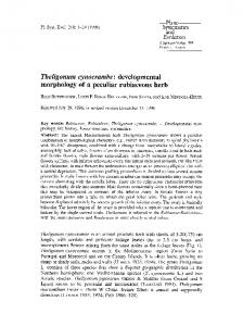
of uMove systems. The semantic model focuses on 1) the entities populating a system and all the properties of the entities including their contexts, the activities and the relations between the entities and their environment and 2) the concept of system observers and viewers which analyse the situation of entities. We also present a functional model of activity and situation representation and integration in uMove. Chapter 4 This chapter presents the architecture of the uMove system and tools which designers and developers can use to theoretically define and design their system and all of its components (users, physical spaces, sensors, contexts, activities and situations). Chapter 5 We present a programming tool that allows the implementation and the setup of a uMove-enabled system in which the physical (or logical) world is virtually represented. These APIs allow to create a middleware with which uMove-enabled applications or services can interact and can gather contextual information such as location or activity of active users or objects in order to trigger appropriate events and actions. This chapter also describes the prototype of the uMove System Editor allowing to 1) set up a uMove system by using a graphical user interface and 2) to load uMove enabled services for Android smartphones. Chapter 6 . Applications implementing the uMove concept are presented in this chapter. We describe in detail the projects and also the issues we wanted to test with each application. Chapter 7 . We draw conclusions and present future perspectives for this research. Figure 1.3 shows how the whole thesis is structured around the two aspects, three facets and the integration of the kinetic properties within the uMove framework.
Figure 1.3: Structure of the thesis: the three facets and the integration of the kinetic properties
Chapter 2
Background and related work Contents 2.1
Ubiquitous and pervasive computing . . . . . . . . . . . . . . . . .
9
2.2
Ubiquitous computing: definition of the paradigm
. . . . . . . .
10
2.3
Context-aware computing . . . . . . . . . . . . . . . . . . . . . . .
13
2.4
Human-computer interaction in ubiquitous computing . . . . . .
23
2.5
Activity-based computing . . . . . . . . . . . . . . . . . . . . . . .
26
2.6
Reasoning on situation: an evolution of activity-based computing 30
2.7
Summary . . . . . . . . . . . . . . . . . . . . . . . . . . . . . . . . .
32
In this chapter, we analyse existing research, concepts, paradigms, middlewares and technologies used in ubiquitous or pervasive computing projects. We present some aspects and components which generally constitute Ubicomp systems and which are related to the uMove project and model. We also review the evolution of Weiser’s vision and see where we stand now. The chapter also includes the HCI aspect in the context of Ubicomp, as well as current research in User-Ubiquitous Computing Interfaces and, in particular, we study some theories and models that support the integration of user motions, activity and situations as possible interaction paradigms.
2.1
Ubiquitous and pervasive computing
Thirty years ago, the concept of ”computer” almost exclusively referred to mainframes processing input data and producing output results. At that time, the interaction between users and computers was extremely limited and users were more often considered as operators than clients. That was the first computing era with the concept of ”one computer-many users”. Then, with the development of personal computers (PCs), the second era of computing began: 9
10
Chapter 2:
Background and related work
”one computer-one user”. At that time, we saw not only the user operating the computer but also clearly interacting with it through graphical user interfaces, keyboards and mice. In the late ’80s, Mark Weiser, working at Xerox PARC, proposed a new computing concept called ubiquitous computing (Ubicomp) [Weiser, 1991]. This new way of understanding computer technology came from the fact that computers became smaller and could be embedded into everyday things. It was a paradigm shift between ”one computer-one or many users” to ”many computers-one user”, and the beginning of the third computing era (Fig. 2.1).
Figure 2.1: The three modern computing eras (source: [Krumm, 2010, ch.1])
The term ”Pervasive Computing” was proposed by IBM in the mid-90s (IBM Mobile and Pervasive Computing), and had almost the same meaning as ubiquitous computing. Ubiquitous computing tends to integrate disparate technologies to meet a design goal and pervasive computing tends to develop wireless and mobile platforms running standardised operating systems deployed in the form of smart phones (IBM WebSphere or J9, Android and Java platforms). However, Want states in [Want, 2010, p.11]: ”more than 10 years later, any unique position described by either party has been slowly integrated into the shared vision and by the mid-2000s any publications that set out to describe this topic presented fundamentally the same position”. From now on, we will use the term Ubicomp to describe both paradigms.
2.2
Ubiquitous computing: definition of the paradigm
What fundamentally changed between desktop computing and Ubicomp? Ubicomp is a subarea of Distributed Systems and its main focus is research on how heterogeneous, networked computing devices can be embedded in objects of daily use to enable applications to create new user experiences. Weiser’s vision of Ubicomp was that computing will be embedded in everyday artifacts, used to support daily activities, applicable to our work, managing our homes, and for play [Want, 2010, p.4]. In other words, the computer, as we know it now, will disappear into our environment and the computing power will fade inside the network
2.2:
Ubiquitous computing: definition of the paradigm
11
infrastructure. Consequently, we will have more heterogeneous computing devices ranging from small, specialised and interconnected devices to high-performance servers scattered in our environment. Weiser’s vision of ubiquitous computing has been largely adopted by the scientific community [Dey et al., 2001, Loke, 2007, Abowd and Mynatt, 2000, Abowd et al., 2002, Greenfield, 2006, Bellotti et al., 2002] and Weiser is probably the most cited author in the field of Ubicomp and Pervasive Computing.
2.2.1
Ubiquitous computing is not nomadic computing
Ubiquitous computing is often confused with nomadic computing and mobile computing [Kleinrock, 1997]. Nomadic computing is the form of computing where the user can access his data any where and any time while on the move. In the past fifteen years, we have witnessed a substantial increase of mobile computing devices such as laptops, personal digital assistants (PDAs) and smartphones. The main trigger of this change was the significant evolution of the networking and (tele)communication capabilities. The Internet became part of our lives and wireless communication in now available almost everywhere in different forms such as GPRS, UMTS or WIFI. Other factors that have boosted the development of these technologies are the need for mobility in our societies, and the decreasing cost of hardware and services. Access to information (private or professional) and the ability to work everywhere or to be reachable at all times have entirely become part of our lives. However, and even if we consider the paradigm shift between desktop computing and nomadic computing, it is still a kind of (mobile) desktop computing: there is still a direct and explicit interaction between the human and computers. Ubiquitous computing goes beyond this concept. In Ubicomp, as we will see later on, the user does not necessarily interact explicitly with the computer through a screen, keyboard and/or mouse. As stated by Weiser1 : ”[ubiquitous computing] is different from PDAs, dynabooks, or information at your fingertips. It is invisible, everywhere computing that does not live on a personal device of any sort, but is in the woodwork everywhere.”
2.2.2
From Weiser’s vision to now: where do we stand?
Rare are the papers on Ubiquitous or Pervasive Computing that do not refer to Mark Weiser’s fundamental article [Weiser, 1991]. Twenty years of research and a substantial amount of projects have taken their inspiration from the central idea of ”computer everywhere” and ”calm technology” [Weiser and Brown, 1996]. The questions now are: Is this vision of computer everywhere a reality? Do we have concrete projects that implement the concept of calm 1
http://www.ubiq.com/hypertext/weiser/UbiHome.html
12
Chapter 2:
Background and related work
technology or ubiquitous computing? Did we reach the goals of calm technology? For the first question, it is undoubtedly the case. For the other two, the answer is rather negative. As mentioned by Rogers in [Rogers, 2006], considerable efforts have been made to realise Weiser’s idea by developing frameworks, technologies and infrastructure to support people in their daily life, but ambitious projects such as HP’s cooltown, IBM’s BlueEyes or MIT’s Oxygen are still far from reaching the goal. And, even if our environment is augmented and sensed by several sensors creating smart homes or smart environments, they do not match up to a world of calm computing. Bell and Dourish in [Bell and Dourish, 2007] argue that a gap exits between Weiser’s vision of Ubicomp, particularly in the technological development, and the present time. The invocation of this vision ”neglects the significant difference between then and now, and [the] changing techo-social contexts”. In other words, they say that ”today’s technological landscape is quite radically different than that of the late 1980s”. Bell, Dourish and Rogers’ arguments highlight two main problems. The first one is situated at the interaction level. Calm technology is supposed to help users release unnecessary cognitive load while interacting with computing systems and carrying out other human activities at the same time. Because users are surrounded by several computing devices simultaneously, those devices should not take a user’s full attention. It means that the interaction mode with Ubicomp systems must be smooth and implicit and the technology should be put at the periphery of user attention [Weiser and Brown, 1996] if any action is required. The level of attention required by the different computing systems is adaptable and it moves back and forth. The problem we face today is that computer systems are intrusive and capture the attention of the user (e.g. large public displays, mobile phones, GUIs on laptops or desktops) or require direct interaction too often. The second problem is situated at the technological level. When Weiser published his article in 1991, his vision was already implemented in lab conditions, ”complete with photographs of devices that had already been designed and built, and reports on their use” [Bell and Dourish, 2007]. But technology did not follow exactly the same way that Weiser predicted and we moved from desktop computing to nomadic computing. With the miniaturisation of desktops which were transformed into portable computers, laptops, PDAs and netbooks, we do not reach the idea that computers will fade into the infrastructure but rather they physically surround us and are part of our lives. However, Want argues that smartphones are not so far from the original Xerox ParcTabs2 [Want, 2010, p.30]. Telecommunication has also completely changed our way of living with exponential development of mobile phones and in particular smartphones. As mentioned by Bell and Dourish, the first cellular service begun 1983 in the US and in 1988 there were approximately 1.6 million subscribers. According to Want, in 2008, 1.2 billion cell phones were shipped and we reached the level of 3.3 billion subscribers around the globe. 2
http://sandbox.xerox.com/parctab/
2.3:
Context-aware computing
13
The market and the development of mobile technology have clearly driven the research on Ubicomp. Instead of experiencing Weiser’s original idea of calm technology, we have rather desktop applications adapted to mobile computers (with a small portion of screen) that allow users to communicate or get contextual information and services while moving. Even if the surrounding user environment is enriched with sensors and computing power appears in everyday life objects such as proposed in the MediaCup project [Beigl et al., 2001], we are far from the idea of a user being surrounded by technology observing and acting in an unobtrusive manner according to user needs. In this thesis, we explore the possibility for Ubicomp systems to take advantage of this new generation of mobile, interconnected and sensor equipped technologies for the development of applications that stick to the original idea of calm technologies and interfaces. We propose an architecture which uses recent technologies such as smartphones or smart environment and supports the development of context-aware applications able to provide useful and non-intrusive services for users.
2.3
Context-aware computing
Since the ’90s, there has been a growing interest in context-aware computing. A significant number of journals and conferences have published articles in this area [Hong et al., 2009]. The fact that the computing paradigm has changed from personal computing toward mobile and distributed computing has initiated the development of a new type of application, smarter and more adaptive to a user’s contextual needs. Context-awareness started in 1992 with the ActiveBadge project of Want et al. [Want et al., 1992] which is considered as the first contextaware application [Baldauf et al., 2007]. The ActiveBadge project was an indoor location system based on a badge transmitting a signal each 15 seconds. This signal was recognised and located within a building, giving the physical position of the person carrying the badge. The initial application of this system was intended to be an aid for a telephone receptionist to locate people and automatically transfer incoming calls to the nearest phone extension. In this example, the main contextual information was the location, but context-awareness includes more than one context. As mentioned by Shilit and Theimer, context-aware applications adapt according to the location of use, neighbouring people, hosts, accessible devices and, can examine the computing environment and react to contexts changes [Shilit and Theimer, 1994].
2.3.1
Context: concept and definitions
Even though many researches have studied ”context”, there is still no common definition. For Shilit and Theimer [Shilit and Theimer, 1994] context is defined by the location, identity and changes of nearby entities (people or objects). For Brown et al. [Brown et al., 1997], as for Ryan et al. [Ryan et al., 1998], context is also identities of the people around the user, the season, the time and temperature, for instance.
14
Chapter 2:
Background and related work
There is also a different approach proposed by Schmidt, Beigl and Gellersen [Schmidt et al., 1998]. They define a working model for context in which context has a unique name and defines a situation that a user or device is in. The context contains a set of relevant features. For example, a physical environment context has conditions (e.g. light, pressure, audio), infrastructure and location as important features. For Chen and Kotz [Chen and Kotz, 2000], context is a set of user relevant environmental states and settings that determines an application behaviour. They consider five classes of contexts: 1) computing context, 2) user context, 3) physical context, 4) time context and 5) context history. Korkea-aho [Korkea-Aho, 2000] considers context as situational information and states that ”Almost any information available at the time of an interaction can be seen as context information”. Some examples are : identity spatial information - e.g. location, orientation, speed, acceleration temporal information - e.g. time of day, date, season of the year environmental information - e.g. temperature, air quality, light or noise level social situation - e.g. who you are with, people that are nearby resources that are nearby - e.g. accessible devices, hosts availability of resources - e.g. battery, display, network, bandwidth physiological measurements - e.g. blood pressure, heart rate, respiration rate, muscle activity, tone of voice activity - e.g. talking, reading, walking, running schedules and agendas
Lieberman and Selker [Lieberman and Selker, 2000] propose an approach where context is an implicit input and output for an application and is used with the explicit input to affect the computation and the output (Fig. 2.2). Dix et al. in [Dix et al., 2000] focus on the use of context in the design of mobile systems. They consider four different types of contexts. The infrastructure context concerns the environment in which the mobile device and the application runs. The variability in the infrastructure (wireless communication quality, service availability) can dramatically affect interaction, and it is essential that interaction styles and interfaces also reflect the state of the infrastructure. The system context covers two aspects. The first one is the possibility to have applications distributed within several computing devices. The second aspect is the capability for devices to be aware of other devices and to some extent, applications to be aware
2.3:
Context-aware computing
15
Figure 2.2: Context is an implicit input that influences the computation and the output of a context-aware application, [Lieberman and Selker, 2000]
of other applications. The domain context considers the semantics of the application domain. It concerns the relationship between the application and the user, and the determination of the appropriate interfaces. The physical context is the surroundings the mobile computing system is aware of or embedded into. For instance, embedded computing systems are running into application-specific devices and they may need to know their environmental context (e.g. speed of the car). This information may be used to modify the interfaces, the behaviour, the light intensity or simply be delivered to the user. As mentioned by Loke in [Loke, 2004], the work of Shilit et al. provides a generic definition of what context is Dey et al. [Dey and Abowd, 1999] propose a more operational and broader definition of context: [Context] is any information that can be used to characterise the situation of entities (i.e. whether a person, place or object) that are considered relevant to the interaction between a user and an application, including the user and the application themselves. Context is typically the location, identity and state of people, groups and computational and physical objects. Context can also be seen as a way to represent a problem. As mentioned by Dourish in [Dourish, 2004], software systems being representational, a concern with context naturally leads to a concern with how contexts can be represented and encoded. Taking into account the different definitions of Shilit, Dey and Ryan [Shilit and Theimer, 1994, Dey and Abowd, 1999, Ryan et al., 1998], Dourish regroups four assumptions that underlie the notion of context. First, context is a form of information. It can be known, represented and encoded. Second, context is delineable. It is possible to define in advance for some set of applications what
16
Chapter 2:
Background and related work
counts as the context of activities the application supports. Third, context is stable. Context does not vary from instance to instance of an activity or event although it may vary from application to application. Fourth, context is separable from activities. Activities happen within a given context. Even if there is no universal definition of context, we have pointed out four contexts, or type of contexts, that are presented by the selected authors and with which we work in this thesis: 1. Location: an entity (user or object) is always in a location. It is one of the most used contexts. 2. Identity: the entity must be identified in order for an application to adapt its behaviour. 3. People nearby: who or what is around the entity and what are the relations between them. It can help to deal with privacy issues for instance. 4. Environmental context: what are the physical conditions around the entity. With these four categories of contexts, we can answer the ”where”, ”who”, ”who’s around” and ”in which condition” questions. These types of context are used in this thesis to characterise the situation of an entity (Fig. 2.3).
Figure 2.3: Types of context characterising the situation of an entity
2.3.2
Context-aware architectures and middlewares
The following review refers to work and projects that might seem to be outdated but they represent the fundamental principles of the context-aware computing and are still mentioned several times in recent papers and books [Krumm, 2010, Cipriani et al., 2011]. Contextaware architectures present interesting aspects for the development of Ubicomp systems where
2.3:
Context-aware computing
17
1) user’s environments are enriched by (possibly sensed) contexts, 2) mobile devices are integrated within the environment and 3) the user-computer interactions tend to be as implicit as possible. Context-aware architectures are frameworks and middlewares that support the development of context-aware applications. Among the most known architectures developed in the past twenty years, we find Shilit et al.’s PARCTAB [Shilit and Theimer, 1994] which is considered as the first architecture (software and hardware) a context-aware application could exploit. PARCTAB is a small handheld device using an infrared-based cellular network for communication and acting as a graphics terminal. The applications run on remote hosts and information is sent to the portable device. Applications adapt their content only according to the location of the device. This system can be considered as a ”location-based” system rather than a context-aware system as it deals with a limited number of contexts. Recent context-aware systems include many other contexts such as the user’s profile, the time and the people nearby. The Context Toolkit, developed at the Georgia Institute of Technology [Dey and Abowd, 1999, Dey et al., 2001], is another well known context architecture that supports contextaware applications such as the Conference Assistant or the Intercom, which keeps track of the locations of people and enables people to send messages to other people using voice commands. The Context Toolkit provides a strong formalism for describing contexts at different levels of abstraction and contains three types of objects: 1) Widgets, implementing the sensor abstraction, 2) Servers, responsible for aggregation of contexts and 3) Interpreters, responsible for interpretation of context (Fig. 2.4). The interesting aspect of Context Toolkit is the clear separation of data gathering from single or multiple sensors through widgets3 , the fusion of those data and the high-level description of context. But, it does not provide user environment modelling which is also important in the process of context-aware application development. The Easyliving project developed at Microsoft Research [Brumitt et al., 2000] proposes an architecture able to support and dynamically aggregate heterogeneous I/O devices (TV, video, audio) within a single room. They focus on a middleware facilitating distributed computing using asynchronous messaging, geometric knowledge (relations between people, places, devices and things), detection of the people (in the room) and the service description. The interesting aspect of this project is the management of the relation between users (people) and between a user and the smart environment. However, Easyliving is strongly focused on multimedia technologies and no downloads are available. The University of Illinois at Urbana-Champaign has developed GAIA [Roman et al., 2002], ”a distributed middleware infrastructure that coordinates software entities and heterogeneous networked devices contained in a physical space. GAIA is designed to support the development and execution of portable applications for active spaces”. An active space is a physical boundary containing objects, heterogeneous networked devices, and users per3
Usually widget stands for windows gadget but in the Context Toolkit, it represents a sensor abstraction
18
Chapter 2:
Background and related work
Figure 2.4: Context Toolkit architecture
forming a range of activities. An active space is coordinated by a responsive context-based software infrastructure that enhances a mobile user’s ability to interact with and configure their physical and digital environments seamlessly. GAIA is a meta-operating system and an implementation of a CORBA4 middleware. The interesting aspect of this project is the coordination of multiple situated devices and distributed applications. The limitation is given by a proprietary scripting language and no downloads are available. Reichle et al. [Reichle et al., 2008] propose a context model called MUSIC (Self-Adapting Applications for Mobile Users in Ubiquitous Computing Environments). The authors describe the project as ”a comprehensive open-source computing infrastructure and an associated software development methodology that facilitates the development of self-adapting, context-aware applications in ubiquitous and pervasive computing environments”. MUSIC is built on three layers of abstraction. The conceptual layer allows the definition of context artifacts such as elements, scopes, and entities and their representation based on standard specification languages like UML [Fowler, 2004] and OWL [OWL]. The exchange layer concerns the representation of context (e.g. XML, JSON). Finally, the functional layer is the actual implementation of the context model and can use different platforms such as Java or .Net. The model is interesting for the context management, including the users, but seems to not include the concept of activity associated with the users.
2.3.3
Context-aware applications
As mentionned by Dey [Dey, 2010], context-aware applications look at the who’s, what’s, where’s, when’s. Context-aware applications adapt their behaviour according to the context 4
CORBA (Common Object Request Broker Architecture) uses an interface definition language (IDL) to specify the interfaces that objects will present to the outside world.
2.3:
Context-aware computing
19
in which they run (user, activity, location, time). Here we review some applications of two types in domains where contexts are useful for automatic behaviour adaptation: tour guides and healthcare. As we are interested in location context and activity, the following applications propose interesting solutions for tracking users in their environment and providing adapted services. As mentioned above, the first context-aware application was Want et al.’s ActiveBadge [Want et al., 1992]. Nowadays, this application would be put into the category of location-based services as it deals only with the user’s location. Location (physical and symbolic) is probably the most used context and many projects and devices were developed for this purpose. As mentioned by Hightower and Boriello [Hightower and Borriello, 2001], ”to serve us well, emerging mobile computing applications will need to know the physical location of things so that they can record them and report them to us”. Tour guides are typically a type of application that uses location context and user profile such as the language choice to provide relevant information to the user. The Cyberguide of the Georgia Institute of Technology [Abowd et al., 1997] proposes a stand-alone application preinstalled on a portable device with all information. The Cyberguide receives beacons with a location ID and retrieves locally stored relevant information. The main limitation of this application is the static behaviour of the system due to the local storage of information and it does not take context other than location into consideration. The GUIDE5 project of Lancaster University [Cheverst et al., 2000] proposes a context sensitive tourist guide for visitors to the city of Lancaster. Users carry a laptop connected via WIFI to retrieve information. Based on user preferences and the user’s environment (location), the user obtains 1) broadcasted information about the region or 2) specific user requested information. GUIDE is an evolution of the Cyberguide but still does not use contexts other than the user profile and location. Ghiani’s UbiCicero [Ghiani et al., 2008] proposes an environment which aims at supporting multi-device interaction and games, integrated with a location-aware support exploiting RFID technology. Their goal is to improve a user’s experience while visiting a museum by facilitating access to information available and increasing the interactivity of the environment (Fig. 2.5). In this application, the concept of user-environment interaction is important and reinforces the user experience in a specific environment through a Ubicomp system. Also the RFIDbased tracking system corresponds to our approach of user tracking. This application does not include user activity. Another active research field is context-aware applications in health care [Bardram, 2004, Gong et al., 2005, Catarinucci et al., 2009]. The information needs of hospital workers are highly dependent on contextual information such as location, role, time of day, and activity [Favela et al., 2007]. There exist commercial solutions such as Cisco Context-Aware Healthcare [Cisco, 2009] which enables hospitals to integrate real time contextual information such as location and status of medical equipment and staff into the workflow. They propose a 5
http://www.guide.lancs.ac.uk
20
Chapter 2:
Background and related work
Figure 2.5: UbiCicero environment: the Museum Mobile Guide (Courtesy Ghiani et al.)
complete architecture supporting zone inventory and management, presence applications and condition monitoring. Those applications are interesting as they include the user activity in addition to other contexts such as the location and time of day. However, they often consider static or predefined activities and process real-time motion in order to infer the user’s physical activity. There exist many other domains where contexts are used and the increasing popularity of smartphones running platforms such as Android or iOS (iPhone OS), equipped with different sensors have boosted the development of applications such as Aloqa6 or Jigsaw Beta Context Aware App7 . On Android, ”Aloqa solves both the search and discovery issues by utilising a user’s context - their location, time, preferences and relationships - to notify them in real time of friends, places, events and entertainment opportunities around them without delays” and ”Jigsaw can determine our location and our actions no matter where we are and it would store the data for other applications to use”. This is now possible in mobile computing because of the rapid development of several miniaturised sensors embedded in the handheld devices.
2.3.4
Sensing contexts
Another important issue in context-aware computing is of course the acquisition and the processing of contexts in a broad sense. Integrating contexts into an application also means acquiring contextual data in different ways. We consider two main ways that are relevant in this thesis. One way uses the static description of the context such as the user profile, 6
http://www.aloqa.com/ http://www.bukisa.com/articles/405690 download-jigsaw-beta-context-aware-app-for-symbian-andiphone 7
2.3:
Context-aware computing
21
for instance, using the Microsoft Active Directory8 or even, at a certain level, social profiles available on Facebook or Twitter. The profile of a user can provide administrative or social information that can help a context-aware application to adapt its behaviour. The second way is by sensing the environment and getting real-time environmental information. We have identified two types of sensing. The first one consists in using sensors placed in the user environment and the second one is the use of body or mobile device embedded sensors. Body sensors can provide personal information such as heart rate or blood pressure and are typically used in healthcare context-aware applications. Mobile devices are also equipped with many sensors such as a GPS, a light detector, an accelerometer, a compass and a thermometer, but also Bluetooth and WIFI used to locate people [Benford et al., 2005]. There is still work to be done at the level of data processing and representation [Gellersen et al., 2002, Hung et al., 2004]. In this thesis, we focus on location sensors such as RFID locator or wireless location techniques such as the one presented in the RedPin project9 , an indoor positioning system providing room-level accuracy, developed at the ETH in Zurich [Bolliger, 2008]. RedPin is a finger-print system providing symbolic identifiers such as, for example, the number or name of a room. This project is very interesting because it is a zero configuration Java-based project running on Android and iOS mobile devices. We also consider the accelerometer as a main sensor for the activity recognition with algorithms and classifiers such as k-nearest neighbour (KNN) or Hidden Markov Models (HMMs), na¨ıve Bayes networks, decision trees and Support Vector Machines (SVM) [Mathie et al., 2003, Ravi et al., 2005, Long et al., 2009].
2.3.5
Ambient intelligence and smart environments
User environments are also benefiting from the rapid development and miniaturisation of sensors: they are becoming smart. The so-called ”smart environments” are combinations of network-enabled devices and applications capable of adapting their behaviour in order to provide context-aware services and to make the life of users more comfortable. As proposed by Das and Cook [Das and Cook, 2006], a smart environment can be defined as ”one that is able to autonomously acquire and apply knowledge about the environment and adapt to its inhabitant’s preferences and requirements in order to improve their experience”. They point out four main components that constitute smart environments and which are part of this thesis: smart devices and embedded systems, wireless mobile communication, a computing paradigm and a middleware. Smart environments have become a dynamic field of research and many projects have been developed around this topic. Based on the survey by Endres et al. [Endres et al., 2005], some projects related to this research are taken into consideration here. Among them, there is the EasyLiving project from Microsoft [Brumitt et al., 2000] presented in 2.3.2 as well as 8 9
http://technet.microsoft.com/en-us/library/bb727067.aspx http://www.redpin.org/
22
Chapter 2:
Background and related work
the Aware Home from Georgia Tech [Lesser et al., 1999]. The project provides a three-story, 5040-square-foot (470 m2) home that functions as a living laboratory for interdisciplinary design, development and evaluation of applications such as Aging in place, Technology coach, Family Video Archive, PowerLine positioning or Event detection, Baby steps and others. The interesting part of this project is its implementation in real conditions and not only in a lab, and also the development of user’s ”activity” detection which is one concern of our research. The Aura10 [Sousa and Garlan, 2002] project from Carnegie Mellon University provides a digital ’halo’ of computing and information while trying to reach goals such as maximizing the use of available resources while minimizing the distraction of the user. HP’s CoolTown11 represents real world objects (people, places, devices) through web pages. The web pages automatically update themselves when new information about the real world entity they represent becomes available. Web servers are used for the representation of real world entities, and sensing mechanisms (bar code reader, infrared, etc.) for obtaining URLs from real world objects and accessing their web representation. This project is probably the closest to our goal in the sense that it deals with the virtual representation of people and the relations with their environment. However, it is limited to web-based technology and seems to not integrate the concept of activity. MoCA [Viterbo et al., 2007], proposes a service oriented solution for smart environments and is focused on applications which need to find appropriate services (such as a printing service) and which do not necessarily involve a user. Metaglue [Phillips, 1999, Coen et al., 1999] from MIT is part the Oxygen project12 and is a framework which seems to be particularly suitable for developing distributed information systems spread over many devices and users, using agents as the basic underlying paradigm. Different aspects within those topics are investigated such as security, authentication [Abdallah et al., 2007] and monitoring of user activity [Hussain et al., 2009].
2.3.6
Discussion
In this section we have presented a concept which has changed the way of developing applications. Context-awareness has become a major trend in computer science since the ’90s and we have reviewed three aspects that are related to this research. The first aspect is the definition of context. We have seen that there is no universal definition of context but we have identified types of contexts that are commonly used in the computer science community. We believe that the first context to consider is the location. There are no context-aware applications, to our knowledge, that do not integrate the entity (user, place or object) location as context. The second one concerns the identity of the entity. The identity context helps to adapt the application behaviour according to the entity 10
http://www.cs.cmu.edu/ aura/ http://www.hpl.hp.com/techreports/2001/HPL-2001-22.pdf 12 http://oxygen.lcs.mit.edu/Overview.html 11
2.4:
Human-computer interaction in ubiquitous computing
23
interacting with it. The third type of context is the physical environment around the entity. It concerns elements such as time, temperature and light intensity for instance. Finally, we also consider relations between entities as an important context to characterise the situation of the entity. The second aspect is the types of architectures and frameworks that were developed during the last decades. We noticed that there are four distinct approaches: 1) supporting the programming with context (from sensors to high level context representation), 2) setup of a complete a context-aware infrastructure and applications with which the user interacts, 3) setup of context-aware infrastructure supporting the dynamic integration of mobile applications and 4) web representations of entities and the dynamic association of contextual services. To our knowledge, none of these approaches and projects propose a clear modelling tool that designers and programmers can use to theoretically define user environments (possibly smart environments) independent from the context-aware applications and/or services they will provide on top of the environments. The third aspect is the application domain of context-aware computing. We have presented two relevant types of context-aware applications that illustrate a need for the considered contexts. The first type is related to location-awareness and the contextualisation of information content available for the user. The second concerns the management of information related to activity in healthcare. We found that the Ubicomp domain needs to be further explored in terms of: Comprehensive architectures that integrate flexible sensing mechanisms associated to the environment and entities. Modelling tools to clearly separate the representation of an environment made of entities (users, places, things) and context-aware applications or services. New modes of interaction that are more implicit and are based on user activity and the context in which it is carried out.
The last point is important because it concerns the difference between the current state of Ubicomp and its original idea. The next section will present the HCI aspects that can bring current approaches of Ubicomp closer to Weiser’s calm computing concept.
2.4
Human-computer interaction in ubiquitous computing
When HCI intersects Ubicomp, many assumptions that are made when designing interaction for ordinary computing devices are no longer valid. In Ubicomp, computers exist in different forms and only a minimal portion are ordinary desktop computers. As pointed out by Weiser and other Ubicomp researchers, interacting with a ubiquitous system should be done through unobtrusive interfaces. More precisely, interfaces that should not capture the full attention of
24
Chapter 2:
Background and related work
the user, who should still be able to use the system when performing other foreground tasks (Calm computing) [Weiser and Brown, 1996]. Weiser stresses the importance of adapting computers and their interfaces to human space and activity rather that the other way around. In this vision, computers should follow users in their daily activity and be ready to provide information or assistance on demand.
2.4.1
Post-desktop paradigm of interaction
Weiser’s idea of Ubicomp pushed researchers to develop a new way of understanding computer technology, and also the necessary paradigm to interact with such systems. As defined by Dix et al. the term interaction is ”any communication between a user and a computer” [Dix et al., 2004], where computer means any technology, process or system, which in turn could have non-computerised parts including other users. In desktop computing, HCI mainly focuses on Graphical User Interfaces offering the WIMP (Windows, Icon, Menu and Pointer) metaphor, and this interaction paradigm is clearly oriented toward direct manipulation of graphical objects through a mouse and keyboard. Technological advancement over the last fifteen years also allowed the development of mobile phones, smartphones and PDAs with styli, tablets and touchscreens [Quigley, 2010, ch. 6.1.1]. More recent research proposed the development of game controller input or gesture-driven control for game platforms such as Microsoft Xbox and Kinect13 or the Nintendo Wii14 . There are other aspects that are considered in human-computer interaction such as manipulation of physical objects in the user environment. This paradigm has been defined by Dourish as Embodied Interaction [Dourish, 2001] and aims at exploring new interaction patterns where the user-computer interface is moved off the screen and put in the real world. For instance, the Tangible User Interface (TUI) paradigm [Ullmer and Ishii, 2000, Holmquist et al., 2004] replaces the desktop GUI paradigm by a direct manipulation of physical objects called ”phycons”. The motion of objects in physical space triggers the execution of operations and actions such as object selection, service requests and application launching (e.g. music player). In [Rekimoto, 1997] the Pick&Drop pattern, an extension of the Drag&Drop pattern, has been proposed to move items across computers. Fitzmaurice, in his work on Graspable User Interfaces [Fitzmaurice, 1996], proposes to extend interaction with classical GUIs by means of physical objects (e.g. LEGO bricks) over an augmented desktop surface. There is an alternative class of interaction with computing systems called the Surface User Interface (SUI) [Quigley, 2010, ch. 6.3.2]. The system relies on self-illuminated liquid crystal displays (LCD) or projected surfaces of different size. The interaction is relatively close to TUI by using computer vision and motion detection, acoustic wave detection or resistive membranes which determine user input. SUI is typically used in public places (kiosks, ATMs) or in many personal devices equipped with touchscreens (smartphones, PDAs). 13 14
http://www.xbox.com/en-US/kinect http://www.nintendo.com/wii
2.4:
Human-computer interaction in ubiquitous computing
25
Even if TUI, SUI and Graspable Interfaces are a great achievement in HCI, they are strongly biased by GUI interfaces: almost no new types of interaction induced by the nature of physical space and objects have been proposed other than replicating those available on desktop GUIs and using the WIMP metaphor.
2.4.2
From GUI to UUI: a new opportunity for human-ubicomp system interaction
Ubicomp has the potential to simplify people’s lives through digital environments that sense, adapt, and respond to people’s needs. This means that systems should be capable of detecting a user’s behaviour, motion, gesture and intention. As pointed out by Greenfield [Greenfield, 2006], new physical interaction such as Rekimoto’s DataTiles project [Rekimoto et al., 2001] represents only a short step to purely gestural interaction like the one present in Steven Spielberg’s movie ”Minority Report”. As discussed in the previous section, the majority of actual user interfaces made for potentially pervasive devices still involve the user in a direct interaction. In recent years, we have seen a new mode of interaction increasingly used in the design of ubicomp systems and user experiences: sensor-based interaction. Originally designed to measure the environment, sensors (thermostats, light intensity, infrared) were transmitting data to systems which were then controlling different devices such as heating systems, lights and air conditioning. Nowadays, sensors are increasingly used to control appliances that previously required physical manipulation by the user. As mentioned by Ensing [Ensing, 2002], in the last decade, more and more sensors have been used to improve the capabilities of applications. A basic example is an automatic light switch using a motion detector or an infrared sensor. The information transmitted is the input of the application. It creates a context and based on it, the application can produce a result. We experience a shift of physical-interaction toward sensor-based interaction. The problem with this shift of interaction mode is that in most situations, humans like to keep control of their actions and interactions [Shneiderman, 1998]. As mentioned by Rogers and Muller [Rogers and Muller, 2006], ”The lack of control in sensor-based interactions can result in frustrating, annoying and distracting user experiences - especially when people are caught unaware”. Bellotti et al. [Bellotti et al., 2002], address the problem of designing sensor-based systems taking into account the user, the system and expectations during the interaction (e.g. input protocol, feedback, mistake correction). Another problem that is often discussed is the accuracy of data acquired by the sensors and the inferences themselves which can be imperfect and therefore may cause imperfect predictions. This means that actions should be triggered with caution. However, sensor-based interaction is part of our life and we do not notice it anymore. For example, the majority of shopping centres or airport entrances are equipped with automatic doors and we are not systematically looking for a handle when entering these buildings.
26
Chapter 2:
Background and related work
Sensor-based interaction can be used in two different ways. The first one consists of replacing the physical contact to control a computing system or devices such as taps and switches [Rogers and Muller, 2006] by motion and gestures, which are explicit and purposeful. In the second one, the system reacts according to implicit actions executed by users. As proposed by Ju et al. in their example of interaction with smartboards, they use the current distance between the user and a smartboard to engage diverse interactions such as removing a screensaver or erasing the previous ”whiteboard” content and getting reading for new drawings [Ju et al., 2008]. Dix [Dix, 2002] proposes the concept of incidental interaction and defines it as ”where actions performed for some other purpose, or unconscious signs, are interpreted in order to influence/improve/facilitate the actors’ future interaction or day-to-day life”. Incidental interaction is situated at one end of a spectrum of interaction. This spectrum is a continuum where in the other end is intentional interaction. Intentional interaction includes all purposeful commands that a user is giving to the system, whatever interface it uses (GUI, TUI, SUI or sensor-based). As our environment is increasingly sensed through various devices (mobile phones, movement detectors, locators) and computers become more invisible or integrated in the physical environment, we are inevitably moving toward implicit Human-Computer interaction (iHCI) [Schmidt et al., 2005] where human activity (action and motion) is integrated to enrich the contextual information. Even if the HCI in generally associated with the concept of GUI, we consider in this research that iHCI can be associated with our concept of Kinetic User Interface (KUI) as its goal is to take user’s motions and activity as an (possibly the main) input modality like in activity-based computing. In the next sections, we review some work and theories of activity-based computing and situation reasoning that are considered in this thesis.
2.5
Activity-based computing
This thesis does not propose activity-based applications but focuses more on how user interaction with Ubicomp can include the user’s activity. We need to study what is currently done in activity-based computing and what kinds of models are usually considered, in order to integrate them in our model and architecture. The goal is to offer an architecture that supports such a paradigm and allows designers and developers to create activity-aware applications. Even if context-awareness has brought a new dimension in the way users interact with computing systems, Activity-based computing is one of the most promising steps toward Weiser’s vision of Ubicomp. For Dey et al. [Dey et al., 2001] or Korkea-aho [Korkea-Aho, 2000], user’s activity is part of their context. Dourish [Dourish, 2004] argues that activity is separable from the context and an activity is done within a context. As discussed in chapter 3.5.3, we share Dourish’s opinion. However, human activity represents important contextual information to make applications smarter. Up to now, often only environmental
2.5:
Activity-based computing
27
contexts provided information to adapt the application behaviour. But, if they are enriched by associating a current activity then the system can better infer on the user situation and can react differently and more appropriately. For example, a smartphone changes its setting (is put in silent mode) when it is located in a given place (in a meeting room). If the user activity is added as a new parameter then it might react differently. If the user is ”having a meeting” (the activity) then it is appropriate to set the phone in silent mode. But if the activity is ”reading a report” and the location remains the same, meaning in the empty conference room, then the device can simply not react (stay in ring mode). Integrating activity as a main input modality allows to develop more implicit or incidental interaction [Dix, 2002] with computing systems. The majority of research concerning human activity recognition only considers physical activities. These are defined by Preece et al. as ”any bodily movement produced by skeletal muscles that results in energy expenditure above resting level” [Preece et al., 2007, p.31]. Bodily movements can be relatively easily measured and identified in laboratory conditions, however the use of isolated actions in analysing real-life situations outside of a laboratory is much less fruitful. As mentioned by Kaptelinin [Kaptelinin, 1996], the lack of an adequate theory of HCI has pushed researchers toward Activity Theory (AT) as a possible framework for the development of new HCI models. Bødker [Bødker, 1990] presented the basic idea and potential benefits of activity theory to the HCI community. Since then, many papers have been written on AT and HCI [Nardi, 1992, Norman, 1991, Draper, 1993, Kaptelinin, 1992, Kuutti and Bannon, 1993].
2.5.1
Activity Theory: concepts and applications
Activity Theory (AT) is a philosophical framework that allows the study of different forms of developmental processes where both individual and social levels are interlinked. AT was initiated by Russian psychologists L. Vygotsky, A.N. Leont’ev and A.R Luria in the ’20s and ’30s. AT is not a strict theory but more a set of basic principles usable in more specific theories. The principles include the hierarchical structure of activity, object-orientedness, internalization/externalization, mediation and development. The object of AT is to understand the unity of consciousness and activity [Nardi, 1995]. It is called the ”principle of unity and inseparability of consciousness (i.e., human mind) and activity” which means that the human mind can only be understood within the context of meaningful, goal-oriented, and socially determined interaction between human beings and their material environment [Bannon and Bødker, 1991]. The basic notion of AT is that the individual participating in an activity does it to achieve a certain goal. Activity is a set of high-level goals and they correspond to either desired states of the environment (e.g. moving from point A to point B) or internal cognitive states (e.g. being happy). Goals can be made of sub-goals. As in holonic systems, a goal can be part of a larger goal.
28
Chapter 2:
Background and related work
After Vygotsky’s early death, Leont’ev extended Vygotsky’s research framework and proposed a model of activity. In his model of activity, Leont’ev distinguishes activity, action and operation. Actions describe what must be done to achieve an activity (to reach the final goal) and they are typically conscious. Activities are realised with individual, cooperative, chained or networked actions related to each other by an overall motive [Kuutti, 1996] (Fig. 2.6). Operations are, in contrast, typically unconscious, routinised actions that require almost no explicit attention. A good example of action-operation is shifting gears in driving. At the beginning, all operations are conscious, coordinated actions, (ease the gas pedal, push the clutch pedal, move the gear box lever). Then it becomes a ”routine” and the level passes from ”conscious” to ”unconscious”. Actions become operations and operations implement actions. An action is performed by executing one or more operations. Operations can be used in many actions and are typically executed by operating artefacts through their ”interfaces”. These hierarchical levels of activity are interesting because they give a clear view of which steps raw data representing the motion should pass in order to become an activity, and this is used in our motion-aware model presented in chapter 3.5.2
Figure 2.6: Hierarchical levels of an activity
2.5.2
Models and tools
Activity-based computing (commonly named ”ABC” in the literature) is an active field of research and there exist different models and tools to support user (human) activity as an input modality for Ubicomp systems. As we are interested in architectures that support the integration of user activity detection, we present a few models and environments where human activity is specifically used as input into Ubicomp systems. Ubicomp research in healthcare is particularly active and often integrates activity in the computing process. We also propose a validation scenario which takes place in nursing home environment where activity of elderly people is monitored (Ch. 6). Bardram [Bardram, 2005] considers that healthcare is an interesting area for the development of pervasive computing systems as it requires extreme mobility, and involves ad hoc collaboration, interruptions, and a high degree of communication. The ABC Framework project [Bardram, 2005] has a runtime infrastructure and a programming API, used to develop activity-aware applications as well as to tailor the behaviour of the infrastructure. The type of activities used in the
2.5:
Activity-based computing
29
ABC Framework are not physical activities sensed and represented in real time but more, as described in the scenarios in [Bardram, 2005], tasks executed or possibly executable (e.g. patient daily activity record or invitation for a ”radiology meeting” activity). Activities are collections of configurations of services and data. Each service needs to be able to hand over state information when needed. According to Bardram, activities can be broken down along three dimensions: 1) task and material: activity is accomplished by carrying out tasks which use or manipulate materials. A computational activity reflects this as a collection of computational tools for carrying out tasks (applications and services), 2) time and space: activities are managed and persistently saved over time, are distributed across computational devices that can handle them, and are directly accessible to users in the user interface. 3) users: activities are inherently shared, are collaborative and can have several participants. Favela et al. [Favela et al., 2007] describe a project in a hospital environment for the estimation of medical staff activity using neural networks. They train the network with the information recorded from a workplace study conducted in a hospital. They claim that with this approach, they correctly estimate hospital worker’s activities 75% of the time (on average) and how, once an application has strong evidence of the user activity, it could adapt itself by displaying information relevant to the task at hand, and infer secondary context, such as availability. They also present an application on a mobile device that implements the concept. Moving out of the healthcare environment, Li and Landay [Li and Landay, 2008] focus their attention on everyday life activity. They discuss Activity-Centered Design (ACD) which is a set of perspective concepts which uses long-term and high-level activity (e.g. ”keeping fit”). They propose an ”activity-based ubicomp prototyping process” supporting activity-centered Ubicomp design. The idea is to analyse and model activities based on field observations and then to create an interaction prototype. They use Activity Theory as ground theory and apply the principle of operation-action-activity (Fig. 2.6) for the analysis and modelling of activities. To represent context-rich human activities in a prototyping process, they extended this hierarchy by introducing three new concepts: situations, scenes, and themes. Actions (e.g. running) are performed in certain circumstances (e.g. in a gym or park and with friends) called situations. The combination of an action with its associated situation creates a ”scene” which represents a real scenario or observation of everyday life. In this article, the authors also present the ActivityDesigner, a graphical application which allows ”a mediarich representation of everyday observations”. ”A designer adds concrete scenarios about everyday life to her design as scenes” and enables the creation of prototypes based on modelled activities by allowing designers to specify stream-based interaction behaviours using direct manipulation and an activity query language. It also supports real world experiments by generating prototypes that can run on different devices allowing continuous in situ testing over an extended time period. It also allows designers to monitor and analyse participant behaviours for the next design iteration. The ActivityManager is very focused on the user
30
Chapter 2:
Background and related work
activity monitoring and proposes the concept of situation but does not allow a third party application to use this information to trigger specific actions. Prekop and Burnett [Prekop and Burnett, 2003] propose a model of context that focuses on capturing and using the context that surrounds the performance of an activity by an agent. They call it activity-centric context. They argue that simply defining context is not enough to be able to use the concept of context to develop context-aware applications. It is also important to understand the properties of context and the relationships between context and other closely related concepts, especially tasks or activities and users or agents. Context can be seen as a container, holding information relevant to the problem or domain being examined. In the activity-centric view of context, the problem is how to identify the information relevant to the activity being performed before the activity has been performed? Their approach is to refine the activity and the associated contexts from more generic activities and contexts to more precise ones. They create cascading activities and contexts. It is an inheritance process. In the paper, they give the example of the organisation of a workshop by an agent (a user). The concerned contexts taken into consideration start from generic ”job context” then ”project context”, ”task context” and finally refined to ”workshop context”. The activity ”organise workshop” is surrounded by all the described contexts. They claim that with this approach, applications can be truly context-aware as they integrate not only the direct contexts but also the contexts surrounding the activity. The interesting point in this approach is that contexts are used to refine activities but they do not consider, as Dourish does [Dourish, 2004], that an activity can be done in different contexts and therefore it creates another user situation.
2.6
Reasoning on situation: an evolution of activity-based computing
The notion of ”situation” has rarely been exploited in Ubicomp but it seems to be an evolution of activity-based computing, as an activity associated with contexts represents a situation [Dey and Abowd, 1999]. In this thesis, we are interested in supporting situations and present two different approaches that have been proposed and developed in the scientific community and review some applications using the situation concept.
2.6.1
Definition of situation
Situation has been discussed and defined by several authors such as Barwise et al. [Barwise et al., 1991], Devlin [Devlin, 1991, 2006], Loke [Loke, 2004, 2007] and Li and Landay [Li and Landay, 2008, 2006]. The first three authors propose a mathematical approach for situation representation. Li and Landay are more focused on activity-based computing where situations are parameters for activities [Li and Landay, 2006]. We often use the word situation in everyday life to talk about context. Situation and context in written language often have different meanings. The Cambridge Advanced Learner
2.6:
Reasoning on situation: an evolution of activity-based computing
31
Dictionary15 provides a definition which clearly reflects this relation: ”Situation is a set of things that are happening and the conditions that exist at a particular time and place. The context is the situation within which something exists or happens, and that can help explain it”. This relationship between situation and context explains why people use situation and context equally in spoken language. Cooper and Kamp [Cooper and Kamp, 1991] define the notion of situation as: ”an object in situation theory which is defined by the collection of infons16 that it supports, where an infon is a situation theoretic object which has a relation, an appropriate number of arguments and positive or negative polarity”. According to Loke, the notion of context is linked to the notion of situation. In [Loke, 2004], he mentions the definition of situation from the American Heritage Dictionary: ”The combination of circumstances at a given moment; a state of affairs”. He proposes the aggregation of (perharps varieties of) contexts in order to determine the situation of entities. In that sense the situation is thought of as being at a higher level than context. Loke makes a difference between activity and situation and considers an activity as a type of contextual information to characterise a situation. Devlin [Devlin, 1991] has included situations in his ontology for the study of information and cognition (based on individuals, relations, spatial and temporal locations). An agent world divides up into a collection or a succession of situations (situations encountered or referred to). That is to say, an agent’s behaviour changes according to the situations it is facing (behaviour of people or mechanical behaviour). Thus, people do not react in the same way if they are in a threatening situation or a pleasant situation. A mechanical device will not behave correctly if it is used in a situation it has not been made for. This vision of situation shows that agents (entities in our model) adapt their behaviour to the situation. A situation includes the individuals, relations, spatial and temporal locations and polarities. In other words, a situation depends on the contexts of an entity. Li and Landay also propose that an activity changes every time it is carried out in a particular situation [Li and Landay, 2006]: ”A situation is a set of actions or tasks performed under certain circumstances”, what we call context.
2.6.2
Situation theory
Situation theory was formulated in the ’80s by Barwise and Perry [Barwise et al., 1991] as a mathematical theory of meaning to support the study of situation semantics in an analytic fashion [Devlin, 1991]. The development of this theory comes as a result of an interdisciplinary effort, namely cognitive science, computer science and AI, linguistics, logic, philosophy, and mathematics. The theory was approached from different perspectives, either from a perspective of proof and mathematical rigor, or from a perspective of practicality. 15 16
http://dictionary.cambridge.org an infon is a discrete informational item representing an entity of the world
32
Chapter 2:
2.6.3
Background and related work
Application of situation theory
One domain where Situation Theory is used is in linguistics. Features such as self-reference, relativisation of assertions to situations and direct access to the relationship between situations make situation theory applicable to many different aspects of language and communication and explain linguistic interest. Nivre uses situation theory [Nivre, 1991] to study spoken language and human face-to-face communication. Devlin [Devlin, 1994] shows how situation theory underlies the way we encounter the world and influences our behaviour and communication in our society. The use of situation theory in computer science was motivated by the mathematical and logical issues that arise within it [Tin and Akman, 1994]. The inference issues in situation theory were the main motivation in Artificial Intelligence (AI). The relationship between information content and situation was used to analyze the information flow. Tin and Akman [Tin and Akman, 1994] review different approaches (PROSIT17 , ASTL18 , BABY-SIT) to computational situation theory and mention that those approaches are especially designed with mechanisms allowing state of art constructs of situation theory. PROSIT is a situationtheoretic programming language [Nakashima et al., 1988] implemented in common Lisp and designed for knowledge representation. ASLT, developed by Black [Black, 1992], is implemented in common Lisp and designed for natural language processing. BABY-SIT developed by Tin and Akman is a computational medium based on situations and aims to provide testing of programs in domains ranging from linguistics to AI by using situation-theoretic constructs. With the growing use of the web and distributed systems, new approaches to use the concept of situation are emerging. These approaches try to use situation theory to adapt an application according to situations. Situation theory is not very developed yet in Ubicomp but as far as the application behaviour can be adapted according to contexts and activity it also concerns the situation of users. The complexity of situation theory and its application has probably prevented researchers from using it. However, Loke proposes LogicCAP, an extension of Prolog which uses the concept of situation programs. A situation program is a logic program which allows to represent situations in a convenient way and can be done by meta-programming. The representation of situation is made of collections of rules. This makes LogicCAP a high-level declarative language. Thus, context-aware applications using LogicCAP can be concisely expressed [Loke, 2004, 2007]. An interesting approach towards the use of situation theory is introduced by Kokar [Kokar et al., 2009]. This approach aims to capture situation-theoretical constructs within a Web Ontology Language. In this approach, the ontology captures facts about the world and by using an inference engine other facts are deduced. The advantage of this approach is that it uses a commonly supported language to express situation and therefore bring situation theory to practice. However, situation theory is, for now, marginally used in computer science and, compared to AT in HCI, not many re17 18
PROgramming in SItuation Theory A Situation Theoretic Language
2.7:
Summary
33
searchers have taken it as ground theory for their projects. It is a mathematical theory which implies an important level of complexity when describing a situation with many parameters (contexts).
2.7
Summary
This chapter has presented some relevant aspects of Ubicomp that are tackled in this thesis and we reviewed different architectures, middlewares and frameworks that support Ubicomp applications. We discussed the problem of context-awareness and types of context commonly considered in context-aware applications (Sec. 2.3.6). We identified two aspects that are further explored in this thesis: 1) Ubicomp architectures and 2) interaction modes with Ubicomp systems. The first aspect concerns the need of architectures that integrate flexible sensing mechanisms associated with interacting entities and environments and the possibility to integrate modules that process contexts, activities and situations of the interacting entities. Furthermore, it seems that there is a need for a better separation between the logical representation of an environment made of different entities and the (smart) applications. The second aspect concerns the interaction mode with Ubicomp and the dichotomy that exists between the original vision of Ubicomp and its actual situation. Ubicomp is supposed to promote natural and implicit interaction with computing systems that fade into our environment and infrastructure. Today we still experience a strong explicit interaction with multiple mobile computing systems we can name nomadic computing rather that ubiquitous computing systems. We have noticed that the traditional desktop computer has been transformed into small and smart mobile computing devices (laptops, pads and smartphones) often associated with the concept of Ubicomp. However, the interaction mode often remains the same, meaning explicit, direct and using sophisticated and adapting GUIs, but it definitely does not implement the concept of calm computing which Ubicomp systems are supposed to promote. Users are interacting with many different devices often at the same time and their attention is fully captured by those ones. With the architecture we will present, we propose a solution to support in the future applications that will allow to reduce the explicit interaction with Ubicomp systems by following the concept called Kinetic User Interface (KUI) which takes advantage of new technologies such as miniaturised sensors put in our environment or in mobile devices to sense user’s motion and activity. The goal is to use kinetic properties as an input modality and therefore develop a more implicit interaction with the computing system that can become truly ubiquitous.
34
Chapter 2:
Background and related work
Chapter 3
Conceptual model Contents 3.1
System modelling . . . . . . . . . . . . . . . . . . . . . . . . . . . .
36
3.2
General System Theory . . . . . . . . . . . . . . . . . . . . . . . . .
38
3.3
System . . . . . . . . . . . . . . . . . . . . . . . . . . . . . . . . . . .
38
3.4
uMove system . . . . . . . . . . . . . . . . . . . . . . . . . . . . . .
39
3.5
Kinetic dimension . . . . . . . . . . . . . . . . . . . . . . . . . . . .
51
3.6
Summary . . . . . . . . . . . . . . . . . . . . . . . . . . . . . . . . .
57
As presented in chapter 1.3, this thesis focuses on the development of the uMove framework which offers a set of tools for the development of Ubicomp systems including those that use motion as an input modality. The framework contains three distinct parts: conceptual modelling, architecture design and implementation tools (Fig. 3.1). They allow to develop the system from its abstract representation to an implemented solution.
Figure 3.1: The three facets of the uMove framework
In this chapter, we present the first part of the uMove framework, the conceptual model, 35
36
Chapter 3:
Conceptual model
and the approach we have chosen to describe the components of a uMove system. The model contains one possible perception of the world, the different objects populating it, the relations between these objects, their behaviour and the objects logical representation. This chapter is divided into two main parts: the first part defines the uMove system, the environment in which entities interact and the way they are observed (Sec. 3.4). The second part presents the motion-aware model, which shows how kinetic properties of entities are integrated in the uMove model (Sec. 3.5). Before describing our model, we need to clarify the notion of conceptual model and the reason to use it. We define a conceptual model1 as a way to outline an approach to a system analysis and modelling project. The model is made of a set of concepts describing an existing system of objects, behaviours, functions, relationships and methods. uMove conceptual modelling is necessary to properly define and clarify the concepts, the components and, in particular, the vocabulary which we will use all throughout the development of the project.
3.1
System modelling
Generally, context-aware middlewares or frameworks provide infrastructures and models to support mobile, user-centric active space applications [Roman et al., 2002], context handling mechanisms [Dey et al., 2001], and integration of heterogeneous devices [Brumitt et al., 2000] and developers usually focus on the design of applications which include sensors and mobile devices used by users. Applications are either strongly coupled to the middleware or are environment dependent (e.g. Guide [Cheverst et al., 2002], UbiCicero [Ghiani et al., 2008]). In the uMove project, we propose an approach which clearly separates the user environment and its logical representation from the sensing layer and the application. As in HP’s Cooltown, where the entities (users, places and things) have a Web representation, our model proposes a logical representation of an environment which evolves independently. This separation of concerns allows applications to change without interfering with the environment. A database, for instance, when queried, provides information to heterogeneous and unrelated applications using protocols such as SQL2 , but lets data evolve separately (by means of other applications). Our approach is motivated by two concepts which, we believe, Ubicomp systems should implement: 1. A system should not be intrusive and should propose unobtrusive user interfaces. 2. The interaction between users and the computing system should be as implicit as possible. 1
also named semantic model” Structured Query Language is a language for querying relational databases, developed at IBM by Donald D. Chamberlin and Raymond F. Boyce in the early 1970s. 2
3.1:
System modelling
37
To achieve these goals, the user environment (physical or virtual) should be observed by components (e.g. software agents) called observers which do not interact with it. The observers send events to the applications which then react and possibly send feedback to users. With observers, an environment is clearly separated from the applications. It is, in some way, similar to the MVC3 pattern first proposed by T. Reenskaug at Xerox PARC and originally implemented with Smalltalk-80 [Burbeck, 1992]. To illustrate the concept of observation, we propose the example of UN4 observers or peacekeepers (blue helmets) placed at the border between two countries during a cease fire (Fig. 3.2). Their role is to watch the environment, to observe movements of troops of both countries (the situation) and to react (or notify) when they detect violations of rules. These rules are established in advance and must be respected by the actors on the field (e.g. soldiers must not cross the no-man’s land). A UN observer reports any incident or violation to the higher level (their hierarchical superior, such as the UN security council). The higher level reacts and makes recommendations to the political institution of each country to change their behaviour and respect the agreements/rules.
Figure 3.2: Example of a UN peacekeeping functional diagram.
Unlike the concept of perception, which is a passive process, observation is a proactive process which allows to react, to adapt, to learn and to progress. We observe the solar system or the universe, a cell, a population, an ecosystem or a social behaviour to learn about them. We also continuously observe everything around us and adapt our behaviour in the environment we belong to. We can see from these examples that the concept of observation includes an observer and an observed element (a single entity or an environment) and generally generates an output. The output can be used to modify the observed entity behaviour (self observation) or to make the external entity modify its behaviour, e.g. a car changing its trajectory after observing a traffic jam in its environment. From a systemic point of view, when an environment and observers are put together they 3 4
Model-View-Controller UN : United Nations
38
Chapter 3:
Conceptual model
are called a system. Systems are everywhere: a cell is a (living) system, a social group is a system, as is the universe. They are all managed by different kinds of rules and their components have roles, and relationships with each other. For instance, our solar system is managed by different forces that make all planets stay in their own orbits and create an equilibrium. In Ubicomp, the challenge consists in modelling the physical or logical environment in which entities live and interact into a conceptual system representing the observed environment in a simple and flexible manner. The solution we propose uses a systemic approach and the conceptual model is based on General System Theory (GST) [von Bertalanffy, 1969, Boulding, 1956, Bouvier, 1994].
3.2
General System Theory
Ludwig von Bertalanffy was a biologist who, in the ’70s, developed the General System Theory (GST), which generalises the concepts of systems used in specific scientific disciplines such as physics, (bio-)chemistry, mathematics, biology, economics or social sciences. As stated by Boulding [Boulding, 1956] : ”General Systems Theory is a name which has come into use to describe a level of theoretical model-building which lies somewhere between the highly generalised constructions of pure mathematics and the specific theories of the specialised disciplines. [...] Each discipline corresponds to a certain segment of the empirical world, and each develops theories which have particular applicability to its own empirical segment. Physics, chemistry, biology, psychology, sociology, economics and so on all carve out for themselves certain elements of the experience of man and develop theories and patterns of activity (research) which yield satisfaction in understanding, and which are appropriate to their special segment”. In other words, General System Theory tends to regroup ideas and central concepts which describe specific systems, and propose general concepts applicable in many kinds of systems. In the case of uMove, GST is an improved theory that offers the necessary concepts to define the types of systems concerned in context-aware systems and smart environments.
3.3
System
There are many definitions of systems. In our model we use parts of the definitions proposed by four authors that we found particularly interesting and relevant to our work. System as complex unit According to Alain Bouvier [Bouvier, 1994, p.18], a system (complex organised unit) is a set of elements (components) in dynamic interaction, organised to reach a certain goal and differentiated within their environment. It has an identity and represents a ”finalised whole” (principle of teleology).
3.4:
uMove system
39
Everything is a system Edgar Morin [Morin, 1995, p.28] writes ”[...] Toute r´ealit´e connue, depuis l’atome jusqu’` a la galaxie, en passant par la mol´ecule, la cellule, l’organisme et la soci´et´e peut ˆetre con¸cue comme un syst`eme”. This means that from atoms to a galaxy, everything can be conceived of as a (more or less complex) system. Types of systems General System Theory defined by von Bertalanffy [von Bertalanffy, 1969] gives the framework and the concepts to model specific systems studied in science. Systems can be inert (dead) or living (evolutionary). A system is said to be inert when every element is static (nothing ”moves”). Living (evolutionary) systems are in constant change. A living system is defined by the dynamism of its elements (interacting with each other). Systems can be open or closed. An open system is defined as a system exchanging matter with its environment, representing import and export, building-up and breaking-down of its material components [von Bertalanffy, 1969, p.141]. In this case the environment of a system can be other systems. For instance, we can see the world as a whole extremely complex and open system. The world (the planet) is one component of the solar system and it is part of the equilibrium of this system. Conversely, a closed system is a system where no exchanges are made with the outside. Entity interaction Boulding [Boulding, 1956] mentioned that an ”individual” - atom, molecule, animal, man, crystal - (entity) interacts with its environment in almost all disciplines. For Boulding, each of these individuals exhibits ”behaviour” (action or change) and this behaviour is considered to be related in some way to the environment of the individual, that is, with other individuals with which it comes into contact or into some relationship. The important points in Boulding’s definition are that: The entity’s actions (activities, behaviour) are related to its environment. Entities have relations with each other.
3.4
uMove system
In our model, a system contains three elements. 1) An environment made of a set of entities, 2) observers and 3) viewers (Sec. 3.4.2). The environment is open and dynamic (living) and its complexity evolves with respect to the entities it contains. An environment can contain sub-environments and consequently, an entity can also be an environment. Definition A system is an observed environment. A system S = (E, O, V) is given by a set E of environments
40
Chapter 3:
Conceptual model
a set O of observers a set V of viewers
Figure 3.3: System diagram
3.4.1
Environment and entities
In the uMove system model, an entity behaviour can be influenced by 1) the interaction with the environment (other entities) it belongs to and 2) by feedback generated by the observer and the processing of the actions it performs in the environment. For instance, an action performed by a student in the cafeteria (environment) can be interpreted as inappropriate by the manager (the observer) who might react and advise the student to change his behaviour. In this case, the student is part of a system which is governed by rules in order to make it work. The observation of the environment assures that those rules are followed and the whole becomes a system. Definition An environment is a set of observable, interacting and interdependent entities, physical or virtual, forming an integrated whole.
Figure 3.4: Examples of environments observed under different points of view
3.4:
uMove system
41
To illustrate the concept of system, figure 3.4 shows two systems. In system A, a chemist observes a reaction through her microscope. The chemist is the observer who reports her observations, the environment is the interacting molecules (the entities) and the microscope is the viewer, defining the scope of the observation. In system B, the astronomer observes a comet approaching a planet with his telescope. The system is defined by the astronomer, the interaction between the comet and the planet and finally the telescope which gives a point of view on the situation. Entities In GST or in the definitions proposed by Bouvier and Boulding, a system is made of elements that interact with each other. Those elements, called entities, are no doubt the main components of the defined systems. In a uMove model, entities are what we observe and they are the main component of an environment. In this section, we define the entity through its main characteristics, which are relevant for our model. Characteristics The characteristics presented below are the necessary ones to define and manage all types of entities within an environment. They are: Identity, Status, State, Type, Location, Structure, Role, Relations and Environmental contexts. Identity and status The identity is needed to differentiate an entity within the environment [Bouvier, 1994]. It is the name of the entity and must be unique. In a Ubicomp system, the identity can contain the name, the description of the entity, and a unique identifier (UID). The status provides information about the mobility of an entity. In uMove, an entity can be either mobile or static. A mobile entity can change its location and is therefore capable of motions while a static entity does not move. Status is dynamic and can change over time. The observer needs the status to infer on the entity’s situation (e.g. a static entity that is moving can indicate an abnormal situation). State and type The uMove model considers entities from real and virtual worlds and an entity has two dimensions of properties: physical and organisational. Physicality is the state of the entity: real or virtual, e.g. a real human or his avatar in a virtual world. The organisational dimension is the type of the entity: physical or logical. A physical entity can be a place, a building with physical boundaries or a graphical object in a GUI which has graphical boundaries. Logical entities are typically all entities defined by rules, such as social groups, geographical zones or name spaces (Table 3.1). As shown in Table 3.1, in most cases, our model allows to classify entities. However, it is not perfect and we see some limitations. For instance, the terms ”physical” and ”real” can be confusing but we have used them and their opposites in order to respect their general and accepted definitions. Another limitation could be in cases where both physical boundaries
42
Chapter 3:
Conceptual model
Table 3.1: Examples of statuses and types of entities in a uMove model
and rules (logical boundaries) are used to define an entity. For instance, some countries may have physical boundaries (e.g. a river) with another country and both governments respect them by mutual agreement (defined rules). In this particular case, the entity falls into both physical and logical types and the context of use must be taken into consideration to decide which one is the more appropriate.
Location Location is an important piece of information that an observer needs to know about an entity. It was one of the first contexts used in context-aware computing to adapt application behaviour [Want et al., 1992]. In the uMove model, the location of an entity is defined by two parameters: the coordinates and the address. The coordinates are considered as the absolute location and are given in reference to a fixed point of origin [McGraw-Hill, 2002]. With a GPS device or software program such as Google Earth, a physical entity can get their absolute location on Earth. In the uMove model, the point of reference could be outside the considered system and is set for the entire system. This means that the coordinate system used to locate an entity should be indicated, in order to convert it if it is different from the one used in the system (e.g. WGS84 vs Swiss Grid format). For virtual entities such as widgets in a GUI, the reference point is one specific coordinate in the graphical interface (e.g. upper-left point of the screen in JAVA). The other location parameter is the address (symbolic location). It shows where an entity is located within the structure of the system. Like with a postal address, an entity is located by following a path, e.g. 51, Wallaby Street, Sydney, Australia (Fig 3.5). Each component of the address represents an entity. For virtual entities such as files, directories or web sites, the URL is usually the address where the resource can be located. In our model, we differentiate physical and logical locations. At the same time and same point of reference (or view), an entity can be in only one physical location but in many logical ones. For instance, if a physical place such as an office is divided into two logical places representing two departments (accounting and marketing) and one particular desk is shared by both of them, an employee working at this desk is physically in the office structure and logically located in the accounting and the marketing department structure.
3.4:
uMove system
43
Figure 3.5: Example of an entity located by its address
Structure The structure of an entity is defined by the entities it is made of. We have introduced the concept of environments containing entities which recursively can be themselves environments under certain circumstances. An environment is therefore a complex element which allows observers to get access to entities it contains. In this model, there exist two types of structure for an entity: simple or complex. A structure is said to be simple (atomic) if an entity does not contain any other entities (e.g. a user). An entity with a complex structure is said to be composed (e.g. a building), contains other entities and must have at least one entity (an atom) and have a dynamic structure. The definition of a structure is environment-dependent in the sense that the same complex entity (e.g. the world) can be characterised differently. As shown in figure 3.5, the entity ”world” is defined by the continents and then the cities, but it could also be defined with states and counties and finally the cities and streets. Figure 3.6 shows the physical structure of an entity. Entity e1 is the root and has a complex structure: e11 (complex), e12 (simple). The structure is represented by a tree.
Figure 3.6: Structure of the entity e1
For example, a house is a complex entity composed of rooms, people and objects. If it is observed, it becomes a system and also the root entity of the system. A room is complex if it contains other entities (rooms or people). The structure of a house can evolve over time depending on people’s locations: At time t, three people stand in the living room. At time t +1, two of them leave the living room (complex entity) and enter the kitchen (simple entity).
44
Chapter 3:
Conceptual model
In this case, there is a change of structure. The entity ”living room” contains only one entity and the entity ”kitchen” which was a simple entity at t becomes a complex one at t + 1 with 2 entities. Role of entity We have seen that entities are made of other entities or located within an entity and, in the different examples, entities were places, buildings, rooms, human beings or objects. This means that an entity plays or has a role in a system and the role depends on the state, type and the structure of the entity. We have defined two roles in our model of a system: Actor and Place. Actor An actor is considered as an ”atom” in the environment, has a simple structure and can be physical (human, object, robot, artefact) or virtual (character in a computer game, widget). The actor’s environment is made of other actors and places with which it interacts and is located within a place. With an actor, only its activity or motion, contextual information and relationships with its environment are taken into consideration. A cruise boat, for instance, has a role of actor if we are interested in its motion information and not what’s happening on board. Place A place is a portion of structured space: it is delimited by physical or logical boundaries and can be real (tangible objects, building, square, rooms) or virtually represented by an artefact in computer games or a window in a GUI. Table 3.2 shows an example of places classified by type and boundaries. Type of places:
Physical place
Virtual place
Physical
Building, room, square, park
Window in GUI, computer games, 3D animation
Logical
Department, zone
Social networks (Facebook, MySpace), web sites, groups
Boundaries
geographical
Table 3.2: A taxonomy of place
Physical boundaries are visible separations such as walls, floors and frames [Vallg˚ arda, 2005]. Both real and virtual places can be physically bounded (building, room, square or window in GUI). In a GUI object, we can also call these ”visual” boundaries instead of physical ones. Logical boundaries are not visible but defined by rules such as political or social agreements. An entity inside a real place defined by physical boundaries cannot be in another place at the same time. By contrast, an entity can be inside two or more places at the same time when those places are defined by logical boundaries and they overlap (Fig. 3.7).
3.4:
uMove system
45
A virtual place with logical boundaries is called a ”group” which is defined as ”An assemblage of persons or objects gathered or located together”5 . A group is a set of entities which share characteristics, follow the same rules or have relations (social networks, associations) between them. In the uMove model, a group is a virtual entity that contains other entities (actors, groups or places) and does not have a ”real” location. The concept of group is very important as it contributes to the definition of some relations between entities. Those relations are used, for instance, to allow or not some interactions between entities when trust and privacy issues are concerned.
Figure 3.7: Entity in two places with logical boundaries
The differentiation between physical and logical boundaries and the multiple logical locations of entities changes the representation of an environment. A physical environment is represented by a n-ary tree since a physical entity can only be in one place at a time and therefore can only have one parent (Fig. 3.7). A logical environment is represented by a graph because it can have multiple parents (i.e. a person can belong to many social groups at the same time). Activities in places In the uMove model, places are where actions, activities, motions and interactions between entities (actors, places) happen. Activities are controlled within a place. Places are governed by rules which determine the possible activities they physically or logically afford (Table 3.3). Physical affordance is typically determined by the shape or the dimension of a place (e.g. limited occupants in a room) and logical affordance concerns the social aspect in real places (e.g. smoking in a non-smoking waiting room). In our model, activities are listed in different categories and are attached to places. Rules allow to check if a detected activity is acceptable or not in a given place. Rules use three categories of activities: authorised activities, forbidden activities and negotiable activities (not necessarily appropriate activities). To illustrate the concept of rules and activity lists, we propose the example of a coffee shop where activities are checked by observers. We have three activities and situations: 1. A customer is quietly drinking a coffee and reading a newspaper. This is considered as 5
American Heritage Dictionary
46
Chapter 3:
Conceptual model
Affordance: Place
Physical
Logical
Real
size, shape
social, organisational, political
Virtual
size of a window or screen
respecting design principles for GUI
Table 3.3: Example of aspects limiting place affordances
an authorised activity. Reading does not harm or bother anyone and a coffee shop is a typical place to do it. 2. If in this coffee shop, ”no smoking” signs are put on walls, there is an immediate reaction from the smoking detection system if a customer lights a cigarette. Smoking is clearly in the Forbidden activity list. 3. We also have the third case (negotiable activity) where nothing is explicitly defined about the smoking policy and someone lights a cigarette. The situation is evaluated and the reaction depends on contextual information, like for example ”is the coffee shop empty or not?” or ”is it lunch time?” or ”are children present?”. Relations The notion of relation was introduced at the beginning of this chapter in the definition of a system and is fundamental in the interaction between entities. In any system, entities have relationships with their environment and those relations, called spatio-temporal relations, are important because they provide information about the state of entities and contribute to the evaluation of a situation. They also allow to define the structure and the logical location of entities. A spatio-temporal relation defines the physical or logical connection between entities with regard to time and mainly concerns the location of entities. When an actor is near a place or another actor at the same time, a temporary spatial relation exists between them. Relations are dynamic and evolve with the movement (change of location) of entities. Our model of spatio-temporal relation is inspired by the spatial relationship used in GIS6 [Calkins]. We differentiate spatio-temporal relations between an actor and another actor or a place (actor-actor/place) and the relation between places (place-place). Actor-actor/place relations An actor-actor/place relation is created between two entities based on their position (location). We have two types of such relations: 1. Proximity (Next To) 2. Containment (Inside) 6
GIS stands for Geographic Information System. It is a computer-based system for capture, storage, retrieval, analysis and display of spatial (locationally defined) data - The National Science Foundation, USA.
3.4:
uMove system
47
Next To is the relation established when two entities are physically close to each other according to a defined distance criteria. Inside is the relation established when an entity (actor or place) is inside a place.
Place-place relations The place-place relation is established between two places. It includes the possible connection of places defined by rules but not necessarily by physical separation. We have two types of such relations: 1. Contiguity (Juxtaposition) 2. Coincidence (Overlapping) Two places next to each other are juxtaposed. An open office divided into two places without physical separations is considered as juxtaposed (e.g. the accounting and the marketing departments sharing the same room). Logical places can overlap and share part of their physical space. For example, land belonging to a village can overlap a natural and protected zone. Both zones are managed by different rules and do not have physical boundaries.
Representation of a relation A relation R is represented by a tuple of size 4 which contains the two concerned entities, the type of relation and a time stamp: R =< E1 , E2 , r, t > E1 , E2 = entities in relation r = type o f relation t = time stamp Environmental contexts Contexts (user or entity contexts) were defined in chapter 2.3 as information that characterises the situation of entities [Dey and Abowd, 1999]. The main contexts used in different projects, architectures and middlewares were the location, the identity and the people nearby. Those contexts were presented above and are, in the uMove model, part of the main characteristics of an entity. In this section we complete the definition of an entity with environmental contexts. They are all contexts that provide information about the surroundings of the entity. Typically, for a physical entity, the temperature, the light intensity and noise level are environmental contexts. For a virtual one, time can be an environmental context. The structure of an entity might be indirectly influenced by the environmental contexts if they contribute to making inside entities change their location like, for instance, in the case of an extreme temperature in the room which might make people inside the room leave.
48
Chapter 3:
Conceptual model
Conceptual link between location, structure, role and relation Entities are defined in a way so that they naturally build a consistent environment, meaning that they are identified, are located and have relations. As shown in figure 3.8, a link exists between the location, the structure, the relation and the type of an entity. The location indicates the position of the entity and therefore it is possible to establish a relation with its parent entity (plain arrows). If the entity e11 is physically located in entity e1 , we can establish an Inside relation and also derive the role ”place” of the entity e1 because it contains at least one entity. The other way to define the role of an entity is by its structure. It indicates which entities it contains (if any) and allows to establish the relations 1) between the parent entity and the children and 2) between the children. An entity located in a place which contains other entities automatically has some relations with those entities (e.g. ”next to” relation indicated by the dashed arrow).
Figure 3.8: Conceptual link between the location, structure, relations and role of an entity
Location and structure are powerful attributes that allow to build and manage (using relations for instance) an environment. Abstract representation of an entity To summarise the concept of entity, figure 3.9 shows all components allowing the proper definition of an entity with its contexts.
3.4.2
Observation
As defined in section 3.3, an environment becomes a system when it is observed. This section presents the second part of the model of system which involves the observation of an environment. The observation level is made of two components: observers and viewers. They provide situational information about the environment to a higher level. The observer represents the processing part of the observation (e.g. the UN observer) and the viewer is the instrument used to observe, giving a point of view on the environment (e.g. binoculars).
3.4:
uMove system
49
Figure 3.9: Composition of an entity in a uMove system
Observers Observers are the ”active” elements that watch the entities in an environment. An observer collects information (activities and contexts) about watched actors and places, analyses it and determines their situations. The observer is programmed with a set of rules and a situation reasoning logic which allow to infer on and to react to certain situations (e.g. dangerous or inappropriate) in which actors could be. Observers analyse a small number of specific situations or even only one unique situation. Our vision is to have more observers but less complexity per observer (e.g. four pedestrians at a crossroad will be watched by four observers instead of only one managing all types of situations of the four concerned entities). Observers are the interfaces between the environment which evolves independently and the higher level which takes actions according to the reported situation of the entities. Viewers The concept of viewer comes directly from concrete examples such as the UN peacekeeper situation in figure 3.2. In this example, the soldier is using binoculars to get information about the situation on the field. The binoculars provide a point of view on the situation and the soldier sees only what is within the field of vision. In uMove, the viewer is based on the same concept and it represents the environment in a certain form (e.g. tree or graph) and can be set to focus on only a part of the environment. Observers can choose different points of view to analyse the same situation (Fig. 3.10 a.). Many observers can choose the same viewers but for different situation analysis (Fig. 3.10 b.). A viewer is a multidimensional filter placed between an observer and the entities. Dimensions A viewer allows (or constrains) the observer to focus on a certain part of the environment. The focus can range from the entire environment to one atom. We have two dimensions in our model of a viewer: range and level. The range is a parameter that influences the scope (the angle) of the observation and the level is the parameter which gives the granularity of the observation. The granularity
50
Chapter 3:
Conceptual model
Figure 3.10: a) 1 observer using multiple views to watch 2 boats, b) multi-observers using one view to watch their respective boat
means the number of components and sub-components in the entity tree that are taken into consideration. For instance, a photographer uses different lenses (wide angle or macro) according to the level of observation. The wide angle lens will give a large view of the landscape but loses all details like ants climbing a tree, or bees on flowers. If the focus is the bees on the flower then a macro lens is needed. The level changes. In real life though, a photographer cannot have a focus at the level of a bee and a wide landscape at the same time. This limitation of range/level is solved in our model.
Figure 3.11: Observation of the ocean structure (first level): 2 boats & 1 island
Figures 3.11 and 3.12 show examples of applications which monitor the boat traffic around the Sydney opera house. This observed environment becomes what we call a smart environment as it is monitored and boats can receive notifications if, for instance, their routes are not as planned or danger is detected. In figure 3.11, the observer watches the activities of the two boats with respect to the island. The range is the ocean (place) and it is interested in the first level. It means that the moving boats (actors) and the island (place or actor) are considered as the bottom of the tree, the atoms of the system. In figure 3.12, the application is interested in the people, so the level changes. The observer is now focusing on the activities of passengers on the boats down to the second decks. In this
3.5:
Kinetic dimension
51
situation, boats and decks change their roles and become places and the atoms are now the passengers in both boats.
Figure 3.12: Observation of the third level of the ocean structure
Like the UN peacekeeper point of view, viewers are dynamic and the point of view on an environment can change over time by changing the two parameters Range and Level in order to adapt to new situation needs for instance. In the two last sections, we described the concept of ”system” made of an environment and observations. We mentioned that the main component of a system, the entity, is capable of activities which are reported and analysed at the observation level. The next section presents the model ”kinetic-awareness” which will allow the integration of motion, activity and situation analysis in a uMove system.
3.5
Kinetic dimension
As previously introduced, this thesis aims at enriching traditional context-aware computing systems by adding the concept of activity and situation in the framework of the uMove system. Interaction with computing systems based on user or object motion and activity is considered as a possible and useful input modality for the type of Ubicomp systems we consider. In this section, we present the concepts of motion, activity and situation and the way they can be integrated in the uMove system in order to infer the situation of entities. Figure 3.13 shows the model and the different levels containing the kinetic components (motion, operation, action, activity). Our model offers a clear separation of concerns starting from raw data (sensor readings) to a high-level semantics (situation interpretation). Observers and entities are responsible for processing their specific information which, consequently, decomposes the complexity of the motion-awareness into small interconnected modules (i.e. entities process their activities and observers interpret situations).
52
Chapter 3:
Conceptual model
Figure 3.13: General diagram of the motion-aware model
3.5.1
Separation between activity and situation
As figure 3.14 shows, the integration of motions and activity can be made at the level of the application with or without the use of the observer concept. This type of integration already helps to limit the explicit interaction by recognising the entity’s kinetic properties (motion and activities) by means of sensors and to generate an appropriate feedback.
Figure 3.14: Activity-based computing: the application processes the input and gives feedback
The uMove model takes into consideration the concept of situation as a way to better evaluate the need of an application to react and generate feedback to an entity (e.g. a user). Figure 3.15 shows a clear separation between the situation analysis made by the observer taking the motion, activity and contexts into account and the application generating the feedback to the user when needed. We now present our vision of motion, activity and situation and the way they are connected in order to be properly integrated in uMove. Even if the purpose of this thesis is not
3.5:
Kinetic dimension
53
Figure 3.15: Situation-based computing: the application receives a situation status including contexts (e.g. time) and gives feedback if needed
activity recognition and situations analysis, we need to study models of those components in order to propose a realistic integration in our framework. The approach to motion-activitysituation we chose tends to be as generic as possible to allow future users (designers and developers) to consider other modelling approaches of activity and situation.
3.5.2
Motion
Motion is the first semantic level of the model and is close to sensors responsible for acquiring the raw data. Motion is a universal property of matter. Everything is moving or is in motion in the universe. From atom to galaxy, every component is in motion. A motion is a continuous change of position over time and is relative to a reference point. In Wiktionary7 , a motion is defined as: 1. A state of progression from one place to another. 2. A change of position with respect to time. 3. A change from one place to another. A motion is more than a simple change of location (context) that happens over time. It is a more or less complex combination of location changes and is recognised as activity or action. Based on the previous definitions we define a motion as follows: Definition A motion is any sequence of movements which involves a change of position of an entity or part of an entity over time and in a given frame of reference. 7
http://en.wiktionary.org/wiki/motion
54
Chapter 3:
Conceptual model
A motion is said to be basic if it is composed of one and only one movement (one change of location) between times t and t+1. Motion is complex if it can be decomposed into more basic movements. Any mobile entity (i.e. actor or place) can produce motions. For example, in a gliding activity, a pilot spiraling in a thermal to gain altitude makes a complex (continuous) motion made of basic ones (turns). We also differentiate two types of motions: exogenous and endogenous. We consider an exogenous motion to be any change of location in a space with a frame of reference external to the actor. The change of location of a walking person is considered as an exogenous motion. An endogenous motion is any change of an actor’s position or part of the actor with a frame of reference centered within the actor. Typically, gesture can be considered as endogenous motion. Endogenous and exogenous motions can be done in parallel and/or be combined to provide more information for the activity recognition. We will see in the next section that combinations of motions create actions and, with the presented model, activities stand in higher semantic complexity.
3.5.3
Activities
Activities are defined as ”lively actions or movements”8 . In Activity Theory (cf. ch. 2.5), activities set high-level goals and they correspond to either desired states of the environment (e.g. moving from point A to point B) or internal cognitive states (e.g. being happy) [Kuutti, 1996]. For Loke [Loke, 2004], activity typically refers to actions or operations undertaken by human beings such as ”cooking”, ”running”, ”reading” or ”listening to music”. In the uMove model, an activity is information that indicates the current goal oriented actions of an entity (e.g moving from A to B, reading, driving). Activity can be physical or logical: A human moving from A to B does a physical activity, but thinking about global warming to find solutions is a logical activity. In uMove, we consider both physical and logical activity. Figure 3.16 shows Leont’ev’s model of activity [Kuutti, 1996, p.30] and the hierarchical relations between actions/operations and the activity (the goal). The uMove model includes motion in the hierarchical level of an activity as it is one of the main components of a physical action/operation (e.g. the movement of a person or the change of position of a graphical object in a GUI). Activity is what the observer needs to know about the entity to infer on its current situation. However, an activity is not sufficient to properly determine the entity situation and an activity is usually carried out in different contexts.
3.5.4
Contexts
Contexts were extensively presented in chapter 2.3 and are part of the entity definition. Referring to Dey’s definition which says that context is any information that can be used 8
Collins English Dictionary
©Complete and Unabridged - HarperCollins Publishers 2003
3.5:
Kinetic dimension
55
Figure 3.16: Hierarchical level of an activity in AT and in uMove model
to characterise the situation of entities [Dey and Abowd, 1999], the uMove model considers the identity, relations, location and the environment of the entity as the main contextual information used at the observer level to infer on the situation. We consider that an entity does activities in different contexts. As shown in figure 3.17, activity and contexts are attached to an entity. uMove systems use different kinds of sensors to gather entity-related data and transforming them into information before using them at the entity level.
Figure 3.17: The sensed data are processed before being sent to the entity level where activity and contexts are stored
3.5.5
Situations
The concept of situation is the highest semantic level of our ”kinetic” model which includes motion and activity-awareness, and is inspired by the work of Loke [Loke, 2004, 2007] and Devlin [Devlin, 1991, 2006] who propose a mathematical approach for situation representation, and Li and Landay who are more focused on activity-based computing where situations are parameters for activities [Li and Landay, 2008, 2006]. Loke makes a difference between activity and situation and considers an activity as a type of contextual information to characterise a situation. For Devlin, a situation includes the individuals, relations, spatial and temporal locations and polarities. In other words, a situation depends on the contexts of an entity. Li and Landay define a situation as a set of actions or tasks performed under certain
56
Chapter 3:
Conceptual model
circumstances. Circumstances are what we call contexts. The following example illustrates the relation between activity, contexts and situation: A person doing his jogging in a shady environment, such as a forest, in the middle of a summer day is in a different situation than when doing the same jogging along a busy road, at the same time and without shade. Our view of situation combines the two visions (contexts and activities) and we define it as follows: Definition: A situation is any activity performed in contexts. As figure 3.18 shows, we divide our model into two parts. First, at the entity level, we have the activities and contexts and include motion detection. Second, situations are analysed at the observer level. Observers get high-level semantic information and do not deal with sensed motions and raw data.
Figure 3.18: activity and contexts are components of a situation
The usefulness of a ”situation-aware” model resides in the willingness to limit the unneeded interaction between 1) the environment being observed and the application and 2) between the application and the user or object of the system. In the jogging example, the situation analysis can allow the system to determine the physical condition of the person and, in case of health danger (heat stroke), send a warning to the jogger. This is a typical danger avoidance scenario which can be extended to many others such as assistance of impaired people or prevention in dangerous working environment. We conclude this section with a bottom-up overview of our kinetic model. As shown in figure 3.13, the model is divided into four levels (sensor, entity, observer and application). We consider that the application has the highest semantic complexity, receiving the events from the observers, and sensors provide the less complex information (raw data) needed at the entity level for interpretation and contexts such as location, acceleration and time. In section 3.5.2, we presented motion as one of the main components (input) of operations or actions. The actions/operations shown in figure 3.13 are one possible model of recognising an activity based on the detected motion. In parallel to the activity process, sensors provide the raw data for contexts associated with the (moving) entities. At the observer level, the situation is derived from the entity activities and the contexts.
3.6:
Summary
57
We will see in the next chapters that, depending on the requirements, the system to be developed can be a context-aware system if only contexts are taken into consideration, or it can become motion-aware or activity-aware if motion and activity are processed. Finally, if the system includes situation processing, it becomes situation-aware. A combination of the components (contexts, motions, activity and situation) is also possible. The presented model and its integration in the uMove framework offers an interesting flexibility in terms of Ubicomp system modelling.
3.6
Summary
In this chapter, we described the model of the uMove system and introduced its different components. We started with the general definition of a ”system” from a systemic point of view and our interpretation and its adaptation to this research. The approach is to model an environment (real or virtual) as a logical representation which will interact with an application. The main component of an environment is the entity which can be a human being or objects (physical or logical). Entities have characteristics such as identity, location, structure and relationships with other entities in the environment and they also include the environmental contexts (e.g. temperature, light intensity, noise level). We differentiated two roles for entities: actor and place. We also presented the concepts of observers and viewers which are the objects in charge of the observation of an environment. We defined a uMove system as an observed environment. Observers do not interact with an environment but only report to the higher level when something happens. The second part of the chapter described the
Figure 3.19: A complete uMove System: logical representation of a school and students being observed by the applications
58
Chapter 3:
Conceptual model
kinetic model of the uMove system. Entities do activities within an environment and are influenced by the contexts in which they are carried out. The combination of activities and contexts creates the situation of the entity. In the uMove model, the main role of an observer is to get the two parameters, activities and contexts, and to determine the situation of one or more entities, and if needed, report to the higher level (the application). Figure 3.19 shows a simple example of a complete uMove system which models a school where students are observed in a corridor. Such tracking could be useful for applications that, for instance, remind the student about a lecture when he/she is located far from the classroom and time is running out to reach it. Or, an application indicating the position of classmates (belonging to the same group) to a student only when he/she is nearby.
Chapter 4
System Architecture, Design and Evaluation Contents 4.1
uMove middleware: a multilayer architecture . . . . . . . . . . .
60
4.2
Mobile uMove system . . . . . . . . . . . . . . . . . . . . . . . . . .
68
4.3
Coordination and communication in uMove . . . . . . . . . . . .
68
4.4
Applications and services . . . . . . . . . . . . . . . . . . . . . . . .
69
4.5
IWaT: methods and tools to test the uMove system . . . . . . .
70
4.6
Summary . . . . . . . . . . . . . . . . . . . . . . . . . . . . . . . . .
74
This chapter presents the second facet of the uMove framework (Fig. 4.1) which is the functional architecture of a uMove system, applications and services.
Figure 4.1: The three facets of the uMove development framework
Based on the conceptual model presented in the previous chapter, Ubicomp system designers need to be able to define the specific architecture and components they need for their 59
60
Chapter 4:
System Architecture, Design and Evaluation
projects. The first part of the chapter (4.1 - 4.4) describes the different components of a server-based and mobile uMove system and its associated applications, the relation between mobile and server systems and the concept of services. The second part (4.5) presents the way in which developers can use this architecture to design a real uMove system and evaluate this design before the implementation phase. Before starting the description of the uMove system, we need to define what we consider as a server-based and/or mobile uMove system and the concept of client-server architecture. First, we will see that a uMove system can run both on a ”server” meaning any machine that is connected to a network (possibly wireless) and on a mobile device able to be connected to a network (WIFI). The server-based uMove system usually manages a more complex system like for example an entire building with many users, floors and rooms. The mobile uMove system often represents a unique user (the unique entity) carrying the mobile device and is connected to a server-based system. We consider this architecture as a client-server one because services running on the server have a client part on the mobile device and the client service (process) interacts with the server service (process) [Coulouris et al., 2001, p.34].
4.1
uMove middleware: a multilayer architecture
A uMove system architecture is divided into different layers representing the sensors gathering the entity data, the environment with all entities, and the observers and viewers which relay the processed entity information to the application. This layered architecture is called the uMove middleware and allows 1) to represent the physical environment, 2) to connect physical sensors to the uMove system and 3) to connect applications or services.
Figure 4.2: General diagram of the uMove middleware
A layered architecture allows for a clear separation of concerns of the different objects in the uMove system and divides the complexity of the whole project into different layers.
4.1:
uMove middleware: a multilayer architecture
61
Another advantage of this type of architecture is the possibility to conceptually change one layer with no consequences for the other layers. As shown in figure 4.2, the uMove middleware is divided into three layers: the sensor layer, the entity layer and the observation layer. Each layer is responsible for the different components of a uMove system and separates the semantic levels of the system. It also has clear interfaces to communicate with the other layers. In the following sections, we present the different layers of the middleware starting with the physical level which is the lowest semantic level of the system and finishing with the highest semantic level represented by the applications and services. We consider that an implemented uMove system becomes a uMove middleware. The term ”middleware” is usually used in computer science to define the software layer that lies between the operating system and the applications on each site of the system [Krakowiak, 2007]. We consider the uMove architecture as a middleware because it offers a platform between the physical layer (sensors, the OS) and the logical layer (applications or services) but also between server-based systems and mobile devices (Fig. 4.3).
Figure 4.3: a uMove middleware connecting the sensors to an application, and connecting server-based systems and mobile devices
4.1.1
Sensor layer
In the uMove model, sensors are an entity’s source of contextual information. A sensor can be individual, meaning that it provides data for one entity, e.g. temperature, GPS coordinates or heart beat frequency. Usually this kind of sensor is carried by the entity on a mobile phone or on specialised devices. A sensor can also be centralised and available for all entities in the system. For instance, an RFID locator system can be a ”server-based” sensor if the active parts (readers) are wired in the building and the users carry only passive tags. In this case, the RFID locator maintains a user ID registry and looks for the corresponding entity
62
Chapter 4:
System Architecture, Design and Evaluation
each time a tag is read in an identified place in the building. If the ID matches an entity, its location is updated. This implies that all entity objects must be connected to this location sensor. However, if the places in the building are equipped with passive tags and the users carry the readers (e.g. integrated in their mobile devices) then, each entity must process its location when a tag identifying a room is read. In this case, each entity is connected to an individual location sensor. The integration of sensors into a system can become complex depending on the type of sensing architecture and the types of sensors. In uMove, physical sensors are separated from entities by sengets 1 which are logical abstractions of the sensors connected to the system. Sengets can be attached to one or more entities depending on the type of sensors. This concept is similar to the ”widgets”, used in Dey et al.’s Context Toolkit [Dey et al., 2001], which are an abstraction of connected sensors. We use the term ”senget” instead of ”widget” because originally, widgets are related to control objects (e.g. buttons or sliders) in a GUI and are visible, which is not the case of the object representing the abstraction of a sensor. The previous example of the RFID location system perfectly illustrates the concept of sengets. As shown in figure 4.4, the generic senget is a ”location senget” and its role is 1) to process a location of an entity with the data received from the different connected sensors (RFID, WIFI, Bluetooth or the GPS) and 2) to send high level location information (the new parent entity ID) to the newly located entity. The received data contain different types of information such as, in the case of an RFID sensor, the read ID tag of a person and the ID of the reader. Information is processed at the level of the senget which matches the detected ID tag with an entity found in an entity registry and the parent entity where the RFID reader is located. Finally, the senget sends the entity ID (not the tag ID anymore) and the location (parent entity ID) to the entity object which then updates its new location. Sengets make the sensor layer flexible and they represent the first semantic level of the uMove middleware by processing the raw data from sensors into uMove objects. They also hide the complexity of the connected sensors from the entity. In our example, if the physical indoor location sensor changes (e.g. from RFID to WIFI or Bluetooth) or the four sensing systems, shown in figure 4.4, are used in parallel, the entity is neither concerned nor aware of it: when one of the sensing system detects a change of location, it sends a message to the senget which then processes it according to the type of information (Tag, MAC address, room name) received. The senget sends only one type of message to the concerned entity, with the entity ID and the new parent entity ID. For the GPS sensor, the location senget sends the parent entity ID as well as the coordinates. Depending on the complexity of the data processing, it may be more appropriated to have one senget per sensor technology instead of one senget accepting all types of data. In the location senget example, the setup could be made with four different sengets, each processing one type of data. 1
Stands for sensor gadget similar to the concepts of widget (window gadget) or phidget (physical gadget)
4.1:
uMove middleware: a multilayer architecture
63
Figure 4.4: Example of a sensor layer implementing a location senget and four types of location sensing technologies
All types of sensors (e.g. temperature, accelerometer, light intensity, compass and hygrometer) are accepted in uMove as soon as they have a driver respecting an interface with the senget object and their data are processed by the senget into a contextual information format accepted by the entity. Sengets use different concepts of processing and communication which are described later in this chapter.
4.1.2
Entity layer
The entity layer is the core layer of the system and contains the logical representation of the physical environment (i.e. users, places, objects) being observed. Each entity (actor, place or zone) is defined by its identity, role, status, location within the environment (logical and physical), structure, contexts and current activity (Fig. 4.5 a). As shown in figure 4.5 b), the
Figure 4.5: a) components of an entity; b) entity location principles: physical and logical parents, and structure
64
Chapter 4:
System Architecture, Design and Evaluation
entity location is defined by 1) one physical location (its parent entity) and 2) one or more logical locations represented by the up arrows. The physical locations of entities organise the environment in an n-ary tree and all entities have a parent node except for the root of the environment (e.g. the world or the building). The logical locations (dashed arrows) organise the environment in a graph because an entity can have several logical locations (parent nodes). The structure of an entity is made of entities (children) which are represented in figure 4.5 b) by the down arrows. As with the root of the tree which has no parent, the leaf entities have no children and their structure is empty. The entity tree (and/or graph) represents
Figure 4.6: Entity layer, sensor layer
the e-space (Fig. 4.6). The entity layer also contains two other components: the relation manager and the activity manager. The relation manager is a component which processes the relations of an entity taking into account its current location and contexts. Relations are not stored within an entity, but processed when needed. This guarantees real-time relations and gives a snap-shot of the entity surroundings by checking what is nearby or inside. The relation manager is provided by the framework and can be used by the developer whenever the state of an entity must be known. Contexts of entities are updated with the information provided by the connected sengets. Sengets send messages (the inter-object communication is presented in section 4.3) to the entity each time they process a change of value received from physical sensors. Contextual information is stored within the entity and contains processed values such as < T emperature ; 37.2 ; celsius > and not raw data.
4.1.3
Observation layer
The third part of the uMove middleware is the observation layer which stands on top of the entity layer and is, semantically, the highest level before the applications and services. The role of this layer is to observe the e-space, or part of it, and to report entity changes to applications. It contains three components: 1) the observers, 2) the viewers and 3) the
4.1:
uMove middleware: a multilayer architecture
65
situation management. In a project, the design of the observation layer first consists in a proper definition of an observation strategy. Depending on the type of application, the configuration of observerviewer will be very different. For instance, if the environment is a train station and the application is responsible for observing the misbehaviour of people, such as roller skating fast in the main hall, then one observer and one viewer focusing on the hall are enough. The observer receives all messages from entities located in the hall and processes only their acceleration context. If a person is identified as moving too fast, then it is possible to a create specific observer and viewer focused on this person in order to process a specific situation based on his or her activity. Now, if the application tracks technical staff at the train station in order to optimally assign work or tasks, then another observer-viewer configuration may be set up. Observers can be attached to one or more viewers, and viewers can be used by one or more observers.
Figure 4.7: Two viewers observing the eSpace with two different roots and levels
The differentiation between the observer and the viewer comes from their specific role in the system. The goal was to divide the complexity of the observation process into two specific parts. Viewers are responsible for managing the representation of the environment they focus on and relay all messages coming from entities in the range of their observation to observers. A viewer is set with only two parameters, which are the root entity and the level or the depth of its observation (Fig. 4.7). More specifically, a viewer updates positions, adds or removes entities in the observed tree and relays entity events to the connected observers. Conceptually, the observers are the interfaces between the eSpace (through the viewers) and applications or services. Their role is to receive entity events such as changes of location, identity, contexts, status, structure or activity. An observer is used to process and filter entity events according to the application needs. The idea is to provide only relevant information to an application and ignore the rest. Different applications observing the same environment may need specific types of information and distinct types of observers processing and filtering events. For instance, a person might have his health condition monitored by one application
66
Chapter 4:
System Architecture, Design and Evaluation
and his time schedule or agenda by another application and, in those two cases, two specific observers are required.
Figure 4.8: Observation layer completing the uMove system architecture
In the observation layer, the event processing essentially concerns the situation of the entity. For each received event, the entity situation is (re-)evaluated by the attached observers and their situation managers (if they are present) and the result (situation status) is sent to the application level (Fig. 4.8). If no situation managers are attached to the observers then events (e.g. entity contexts changes) are processed by the observer logic (e.g. filtering some events) and if necessary sent to the application. However, it might happen that applications need to know every change of the observed entities and the observers are set to relay everything without event or situation evaluation. The uMove middleware can be used without any processing between the entity and the application.
4.1.4
Message processors
We have presented the different uMove objects (senget, entity, viewer and observer) in the three layers of the uMove middleware and they all ”process” information coming from a lower level in order to be sent to a higher one. The type of processing is proper to each type of uMove object (entity, senget, observer, viewer) and also to each object. This means that, for example, all entities of an environment are independent from each other and can have their own logic processing their specific contexts received from the sengets they are attached to. To make uMove as flexible as possible, we developed the concept of a message processor which
4.1:
uMove middleware: a multilayer architecture
67
was motivated by the need for the senget object, generic by definition, to implement different algorithms depending on the type of connected sensors. Message processors are separated from uMove objects and are objects that implement the specific logic to process the different types of incoming messages.
Figure 4.9: Message processors attached to all uMove system objects
With this concept, developers can define their processing logic without redefining the uMove objects (entity, senget, observer and viewer) and a message processor can be replaced by another one, for instance, more adapted to the new characteristics of the system. This concept was then generalised to all levels and all objects of a uMove system (Fig. 4.9). In the next chapter, we will present standard implementations of message processors for all objects of the uMove middleware, making it usable as such.
4.1.5
Activity and situation manager
As mentioned in the previous chapter, the uMove middleware can be set to be context-aware only or activity and/or situation-aware depending on the application requirements. This means that the middleware can process, or not, an entity’s activity and situation for the whole or only a part of the environment. If activity and situation are taken into consideration, they are processed at the level of entity and observer respectively by two specific objects called the activity and situation managers, which are attached to the message processors. The two managers are independent and must be specifically developed for groups of entities or for each specific entity and observer (for the situation).
68
Chapter 4:
System Architecture, Design and Evaluation
Figure 4.10 shows the flow of information between a sensor and an entity. When a sensor event is sent to the entity (1), the message processor processes the event (2) and, if needed, (3) transfers it to the activity manager for activity recognition and/or update and waits for the answer (4) before storing the activity in the entity. Finally, the entity sends a message (5) through the viewer to the observer to inform it about the change. At the observer level, the same principle is applied for the evaluation of the entity’s new situation using the observer message processor and the situation manager.
Figure 4.10: Context change and activity management at the entity level
4.2
Mobile uMove system
As introduced at the beginning of this chapter, the uMove middleware can be set up as a server-based component. There are two cases where uMove can be set on a mobile device. In the first case, a uMove system can be composed of one entity which has different connected sensors and which runs different location-aware (e.g. using Google maps) or activity-based applications. These kind of systems could run on a smartphone and be used by users when moving. No connections with a server are required; the uMove system is autonomous. In the second case, users should carry mobile devices equipped with sensors providing the server-based system with contextual information. The server processes it and, if needed, sends feedback to users through the mobile device, as in UbiCicero [Ghiani et al., 2008] or GUIDE [Cheverst et al., 2000]. Another advantage of an architecture distributed between a server and a mobile device is situated at the level of the coordination, communication and compatibility of information, which is discussed in the next section.
4.3
Coordination and communication in uMove
The coordination and communication between objects in uMove is managed by a component called the Coordination manager [Hadorn, 2010] detailed in chapter 5.2.2). Its first role is to coordinate different aspects related to uMove objects such as the connection between
4.4:
Applications and services
69
objects or the consistency and priority of the communication, which is based on message passing. The second role of the Coordination manager is to send and receive messages from the uMove objects. This allows the entities, sengets, observers and viewers to transparently communicate with each other and also allows different uMove systems to be connected to one another. Each entity communicates together in the same way regardless of whether they are local (same uMove) or remote (on a mobile uMove). To illustrate this concept, figure 4.11 shows an entity in the server-based system sending msg2 to an observer (dashed arrow) or a remote actor, located in the mobile device, which is sending msg1 to its representation (stub actor) in the server-based system.
Figure 4.11: Coordination: message passing between entities in server-based and mobile uMove systems
4.4
Applications and services
Up to now, the term ”application” was generally used to describe any software component connected on top of a uMove middleware. An application processes the information coming from the entities and generates an output (feedback to users or triggering an action). In this section, the concept of application is further defined and we introduce the notion of service. The difference between an application and a service is situated at two levels: the output and the infrastructure. In the uMove model, an application does not necessarily give an output to the observed user but can trigger actions for the management of the system (e.g. raising an alarm if forbidden activities are detected in a room) or update logs or GUIs (e.g. people tracking system in a building) which are not noticed by users and do not require an interaction. In the case of the RFID locator, users can be identified in the server system only with their RFID badges and the application can send feedback (if needed) by SMS or email. An application can also be web based and communicate with the users via their mobile browser available on their smartphone.
70
Chapter 4:
System Architecture, Design and Evaluation
Figure 4.12: Difference between an application and a service
A service is always proposed to a user (meaning an entity which is observed in the uMove system) and implies an interaction with this user. A service contains a server and a client part. The client service usually runs on a mobile device which can have any kind of user interface (GUI, voice or haptic). A service therefore requires a mobile uMove, while an application does not. Figure 4.12 illustrates the difference between an application and a service. The scenario is a nursing home equipped with a uMove system which runs an Elderly People Monitoring application to detect any medically suspicious activities and one service which helps the elderly people if a problem is detected and they need some advice. This scenario will be further discussed in chapter 6. This last example concludes the presentation of the uMove middleware and the architecture of a uMove system. The next section will present a method to evaluate the design of a uMove system before starting the implementation.
4.5
IWaT: methods and tools to test the uMove system
The uMove model and the related uMove conceptual framework enable designers to specify the architecture and content of their pervasive system.
4.5:
IWaT: methods and tools to test the uMove system
71
Figure 4.13: Project development phases and tools
Once user requirements have been translated into a system design, an evaluation of that design at a functional level, and at a point before actual implementation has begun, can greatly help to reduce the existence of errors in the overall functional design. This type of functional evaluation can help answer questions such as: Is the architecture of the system well designed and robust? Do the individual modules allow for the necessary behaviours? Do the modules communicate with each other as expected? Does the global behaviour of the Ubicomp system meet technical and end-use requirements? A contribution of this thesis is that this type of evaluation has not been done in the past [Bruegger et al., 2010]. The IWaT (Interactive Walk-Through) evaluation method was conceived to fill the functional evaluation gap and was inspired by the family of walkthrough methods from User Centered Design (UCD). The method can be used to test the design and components architecture of a pervasive application to ensure that the various algorithms, strategies, inferences (of activities or context) and measurements (for example from sensors) chosen by the designers or developers operate together smoothly, satisfy user requirements, take into account technical and infrastructure limitations and form a coherent and comprehensive system. Implementation is often costly in terms of time and manpower and it is always difficult to modify code and/or the entire structure of the project if the design is scrutinised only through evaluation of an implemented system (even if this system is only an early prototype). IWaT is intended to be used between the design and implementation phases (Fig. 4.13) in order to reduce the risk of encountering design problems that are usually detected only during the prototype or system evaluation phases. Moreover, it can be used at any iteration in the design process, although its use in early stages of design and development is the most fruitful.
4.5.1
Using IWaT with uMove
The IWaT evaluation was conceived in relation to the uMove framework and the implementation of the uMove concept, and therefore easily fits into the process of designing pervasive system with these tools. In any development process, independently of the method used, there are steps that define the software architecture, possibly the design pattern to be used, the algorithms that need to be developed and the technological and hardware choices. A uMove
72
Chapter 4:
System Architecture, Design and Evaluation
conceptual model helps to rapidly get the main aspects and functionalities of a system, such as the objects involved, the activity or situation algorithms (possibly in pseudo-code) and the sequence of operations. The model is important because 1) it gives an idea of how the components will behave and 2) it encourages reflection on the design [Schon, 1983]. However, a single model itself is not sufficient to assure the validity of its design within the whole system. It therefore needs to be tested together with the models of the other components. The IWaT evaluation method allows for just this type of testing. Once the evaluation has been completed and the conceptual model has either been validated or refined and retested, the system design is ready to be implemented, and the implementation can be done directly using the implementation tools of the uMove framework.
4.5.2
How it works
The IWaT evaluation method assumes that each component of the pervasive system is being developed by a different team. Therefore, for the evaluation, each team comes with the model (for instance the algorithms) they have developed for their component. The goal of the evaluation is to create a physical interaction between the components where the developers become the “processors” and interpret their algorithms. For example, the team responsible for the mobile phone component manually runs their application and sends paper-based messages to the team responsible for the server application. Then, these messages are interpreted by applying the application algorithm in pseudo-code and possibly sending a message back to the mobile phone team. A log of the events is kept on a board where a process sequence diagram is represented (Fig. 4.14).
Figure 4.14: The events are logged on a sequence diagram board
The method clearly shows the flow of information or messages between the components (Fig. 4.12) and quickly gives a good picture of how the system runs in general. An important aspect to consider when preparing an IWaT evaluation is how to prepare the evaluation environment. In particular, careful thought should be given to the physical distribution of the components (the teams) within the space, taking into consideration the message flow between the components since it will have a manifestation in the physical space.
4.5:
IWaT: methods and tools to test the uMove system
73
For example, two components that send messages to one another on a regular basis should not be placed in physically distant locations in the evaluation environment since the team members from those components will have to move on a regular basis as well. Moreover, thought must be given to what types of physical artefacts of the evaluation are necessary. For example, is a board for the sequence diagram of the interaction between the different components necessary? How can the initial and global states of the application be represented? Are extra people necessary to perform tasks such as updating the sequence diagram?
4.5.3
Advantages and drawbacks of using IWaT
As with any other evaluation methodology, there are both advantages and drawbacks to using IWaT to evaluate a pervasive system. Again, the overall goal of the method is to evaluate the general design of a system, and of its components, without having to implement it. IWaT enables evaluation of the design of a system, that its overall behavior works as expected, and that its components collaborate smoothly. A by-product of the IWaT methodology is that it encourages discussion and collaboration among the components’ developers and, as such, favors team building. The method requires functional descriptions of the components, which can be simulated, and depending on the size of the project, the number components and the number of people involved, it can take times to run the evaluation.
Disadvantages In order to do a thorough evaluation, the whole system will need to be run, and as many test cases as possible will need to be taken into consideration. This implies three things. The first is that at least one member of each of the teams for all of the components needs to be present at the evaluation in order to play the ’role’ of the component. It can be hard to arrange for a time when all of the teams can be represented. Moreover, depending on the size of the system and the number of teams involved, a sufficiently large physical space will need to be found in which the evaluation can take place. Second, the process can be slow since a human will be stepping through the algorithm and not a machine. For large and complex systems, this might mean that the evaluation will not be completed in just a few hours, but rather might require a whole day or more. Third, being able to accurately record the steps and artefacts of the evaluation might be difficult for large systems because the number of steps and cases required could become too large to note explicitly in a physical space. Related to this is the issue that the data that is recorded will need to be easy to understand, particularly given the potentially large quantity. These three factors imply a lot of overhead and careful planning which might not be feasible for some situations such as projects which have very short production times or which are being developed by large numbers of dispersed teams.
74
Chapter 4:
System Architecture, Design and Evaluation
Advantages Despite the disadvantages presented in the previous section, we believe that IWaT has several advantages which can outweigh the inconveniences in some situations. The first advantage is that this type of evaluation can save a lot of time and effort during later stages of development if it is done early enough in the system lifecycle. Since the evaluation primarily focuses on testing the inter-operability of the different components, it allows system designers to quickly and accurately pinpoint problems with the information flow within the system and to determine which components are involved in or are causing the problems. This is something that is hard to do when testing individual components, and is even harder to do when testing the system as a whole using prototypes and end-users if careful and detailed logging capabilities are not built into the system from the start. Having information about problem areas available before implementation begins allows designers to reconsider or appropriately modify their design before significant time and effort has been put into the development process. Once development has reached an advanced stage, most stakeholders in the system are very reluctant to make changes except when they are critical, which is understandable given the complexity of pervasive systems, but can also be detrimental to the overall usability and acceptance of the system by end-users once the system is launched. Moreover, this type of evaluation does not require any type of prototype, nor does it require any type of technical infrastructure, such as a wireless network to be in place, which means that it can be done at any time and in virtually any location without having to worry about network failures or other types of technical problems. This method has been published in the Journal of Mobile Multimedia and presented at the MOMM conference 2009 in Kuala Lumpur [Bruegger et al., 2010, 2009a]. A concrete case study is described in chapter 6.3.
4.6
Summary
In this chapter, we have presented the second facet of the uMove framework which consists of an architecture to guide the design of uMove systems consistent with the conceptual model and the predefined specifications of the project to be implemented. This architecture allows to represent the different components that will constitute the implemented system. Starting with the entities which will be active in the system, the designer can also define the sensor and sengets providing the contextual information and the message processors (at all levels) needed to correctly process the events coming from the different levels, and set the observation strategies and the points of view needed for the application level. The architecture also allows to define the number of activity managers needed for the different entities (actor and places) and the situation managers. Once the system is represented, as shown in figure 4.12, designers and development teams can test their architecture using the IWaT method. Finally, when the
4.6:
Summary
75
architecture is accepted by the design and development teams, the project can be implemented with the tool presented in the next chapter.
76
Chapter 4:
System Architecture, Design and Evaluation
Chapter 5
Implementation tools Contents 5.1
uMove API . . . . . . . . . . . . . . . . . . . . . . . . . . . . . . . .
78
5.2
Coordination and communication . . . . . . . . . . . . . . . . . . .
82
5.3
Mobile monitoring . . . . . . . . . . . . . . . . . . . . . . . . . . . .
86
5.4
Mobile uMove system . . . . . . . . . . . . . . . . . . . . . . . . . .
89
5.5
uMove-enabled applications . . . . . . . . . . . . . . . . . . . . . .
92
5.6
uMove System Editor . . . . . . . . . . . . . . . . . . . . . . . . . .
93
5.7
Summary . . . . . . . . . . . . . . . . . . . . . . . . . . . . . . . . .
98
This chapter presents the third facet (Fig. 5.1) of the uMove framework which is the programing tools allowing to implement Ubicomp projects based on the uMove conceptual model and architecture. In the first part of this chapter (Sec. 5.1 - 5.4), we explain the components (API) used to create the uMove middleware, the interfaces needed to connect sensors and applications and the mobile uMove application that runs on Android devices.
Figure 5.1: The three facets of the uMove development framework
77
78
Chapter 5:
Implementation tools
In this project, the APIs and the graphical user interfaces are implemented in Java 6. Java has the advantage of being a popular language in the academic community and also offers a multi-platform programming environment. However, the uMove middleware can be implemented with any object oriented language and platform (.NET and C], C++, Objective C). A uMove middleware uses three APIs which offer the necessary classes, interfaces and methods to build the uMove system and manage the different objects it contains. They are: 1. The uMove API (5.1) 2. The Coordination API (5.2) 3. The MobileMonitoring API (5.3) The uMove API is the main library used to build a uMove system. It uses the Coordination API for the communication between objects in the system and the MobileMonitoring API for the detection and integration of mobile uMove systems (5.4). uMove API also allows to connect server-based applications on top a running system (5.5). The second part of the chapter (Sec. 5.6) presents the uMove system editor, a visual tool which encapsulates the complexity of the programming and manages the uMove middleware.
5.1
uMove API
Any uMove project will use the uMove API or, more precisely, the uMove.jar library. This API contains all classes needed to define entities, observers, viewers, sengets, message processors, and activity and situation managers. The main components such as the entities, observers, viewers and sengets are runnable objects and run in separated threads. The uMove API proposes a specific object, called UMoveSystem, which represents the entry point of a new system and encapsulates the programing complexity of the different uMove objects.
5.1.1
UMoveSystem
A system is created as soon as the UMoveSystem object is instantiated. It encapsulates all the methods allowing the creation of the objects (e.g. entities, observers, viewers) as shown in the following example (Listing 5.1). 1
UMoveSystem kS = new UMoveSystem () ;
2 3 4 5
Entity zone0 = kS . createPhysicalZone ( " Gruyere " ," R´ e gion de Gruyere " , IDTags , null , null , new Coordinates (575000 , 165000 , 800 , Co or d in a te sF o rm at E nu m . CH1903 ) , eGeom , null ) ;
6 7
Senget s1 = createSenget ( zone0 , L o c a t i o n S e n d g e t M e s s a g e P r o c e s s o r ) ;
5.1:
uMove API
79
8 9
Viewer v1 = kS . createViewer ( zone0 , 3) ;
10 11 12
Observer o1 = kS . createObserver ( v1 , new MySituationManager , new O b s e r v e r M e s s a g e P r o c e s s o r () ) ; Listing 5.1: Code sample of UMoveSystem instantiation
The system instantiated in this example is a simple uMove system made of one entity, one observer and one viewer. Already at this stage, an application can be connected to the kS object and can receive events from the observer. The management of the objects is done through UMoveSystem which is the ”handle” of the system. UMoveSystem offers methods to connect the sensors and applications and to access the system objects and all get-set methods to manage them, and also launches all threads when the system is started. Creating an entity Entities, which make up the e-space, are instantiated using UMoveSystem methods such as createPhysicalZone(), createPhysicalActor() and createGroup(). There are three types of entities that can be created: zones, actors and groups. We have chosen these names for clarity reasons when programming the system. They clearly differentiate the role of the entity within the system respecting the conceptual model, and they allow a simple parametrisation of the Entity class during the instantiation of the objects. Zones Zones are typically places (building, rooms) or objects (cars, boats) and have a dimension or a geometry. They can be physical or logical, mobile or static. A zone is defined by giving a location point called ”point zero” and either a set of vectors if it is a polygonal zone or a radius if it is a circular zone. A zone must be located in a parent zone. If the zone is the root of the system, its parent, set as ”null”, is considered as the ”universe” and the system manages it as such. For instance, a system modelling a building will have the building with its physical dimensions as the root zone. This zone ”building” will be made up of floors, and floors may contain sub-zones (offices). The result will be a tree of zones representing the structure of the building. Actors Actors are the physical users or the mobile objects of the system. The actors are considered as atomic entities located in one point with no dimension and no geometry. They move in the tree of physical or logical zones. Groups Groups are special entities which have no logic and no location but contain other entities. Users can belong to several groups, for example a student can belong to the computer science department group, the university basketball team group and the vegetarian group.
80
Chapter 5:
Implementation tools
Groups are a simple way to manage relations between actors and, for instance, help determine situations at the observer level and help applications adapt their behaviour. Parameters As shown in listing 5.1, an entity has different parameters that can be given during the instantiation phase and modified when running. The main ones are: Name and description: the name and description are strings that define the entity but do not identify it within the system; this is done by the unique ID generated when the entity is created. Tags: e.g. IP address, MAC address, RFID tag, Bluetooth name. Physical location: coordinates of the entity. Logical location: the parent entity where an entity is located (except for the root entity of the system). Geometry: shape and dimension of the entity (for places only). Message processor: object implementing the message processing algorithm (Sec. 5.1.2). Activity manager: object implementing the activity recognition algorithm (Sec. 5.1.3)
Senget Senget objects are the interface between the sensors (or specifically the sensor driver class) and the entities. A senget can be created by UMoveSystem and contains two parameters: the entity or entities to which it is attached and the message processor, in order to process the SensorData received from the sensor object.
Figure 5.2: Sensor and senget classes and message passing
5.1:
uMove API
81
As shown in figure 5.2, the AccelerometerSensor class processes the data coming from the physical accelerometer and calls the method setSensorData() of the attached Senget. Then, the Senget transfers the data to the AccelerometerMessageProcessor object and waits for a result (e.g. an Acceleration object) before sending it to the concerned entity. Viewer and observer Viewers are also instantiated by the UMoveSystem and contain two parameters: the entity object which represents the root point of the observation, and the level which is the depth of the observation within the entity tree. A viewer is automatically attached to the entity tree as soon as it is created, which implies that the e-space must be created before the viewer, or that at least one root entity to observe must be set. Observers are instantiated with three parameters: the attached viewer(s), the situation manager and the message processor. If the situation manager is set to null, it indicates to the observer that situations are not considered and all messages or events coming from the observed entities are processed at the level of the message processor and sent to the application level.
5.1.2
Message processor
As explained in chapter 4.1.4, each object at the different levels of a uMove system must instantiate a message processor which represents the logic of the object. Each level has a specific message processor which receives the message from a sender object (entity, senget, observer, viewer), processes it and returns the result to the sender as illustrated in figure 5.3.
Figure 5.3: Sequence diagram of a message processor and activity manager
uMove provides generic message processors for all uMove system objects, but they can be replaced by custom message processors implementing the MessageProcessor interface. At
82
Chapter 5:
Implementation tools
the senget level, we propose a specific message processor called LocationSengetMessageProcessor as the location is a key element needed to manage the entity tree. This is a generic location processor which is able to receive messages containing either GPS coordinates, an RFID tag, a parent entity ID, a Bluetooth or a MAC address assigned to an entity. This message processor processes them and returns a message containing the ID of the entity and its parent entity ID. At the observation level, the viewer message processor implements an algorithm for the management of the entity tree taking into consideration entities leaving or joining the observed part of the tree. The entity and observer objects use special message processors that allow to attach an activity manager and a situation manager respectively.
5.1.3
Activity and situation managers
An activity manager is a class which implements the interface ActivityManager and the method checkActivity(Entity e) which must return an Activity object (Fig. 5.3). This is the only constraint imposed on the developer. The same rules apply for the situation manager, which implements SituationManager and its method checkSituation(Entity e) which returns a Situation object. If an entity or an observer message processor does not use an activity or a situation manager, messages coming from the lower level are processed at the level of the message processor and sent to the higher level. No calls to checkActivity() or checkSituation() are made. All objects described in this section communicate with each other by means of message passing. The communication between objects is managed by the Coordination API. Since both activity and situation are very specific to the context of a project, no activity nor situation manager is provided with the uMove API.
5.1.4
Relation manager
The RelationManager is an object which is always available when a uMove system is started. It is a singleton that can be called to check the current relations of an entity and it offers different methods such as getAllPhysicalRelation(entity) or getInsideRelation(entity). The methods can be used by any uMove object including, for instance, activity and situation managers during the evaluation of the activities and situations.
5.2
Coordination and communication
The Coordination API was developed as an evolution of the first version of the uMove API [Bruegger, 2007, Bruegger et al., 2007] which implemented the concept of Listener based on the Observer design pattern [Gamma et al., 1995] for all communication between uMove objects. The objects were listeners of the sender objects (e.g. an entity object listening to the attached senget). This approach was very efficient for all communications within the same
5.2:
Coordination and communication
83
virtual machine but caused problems for remote objects. The solution was to use JavaSpace and JINI [Freeman et al., 1999, Newmarch, 2006] for remote communication. The advantage of using a tuple space is its asynchronous messaging capability. But, a disadvantage is that each smart environment needs to run and manage a JINI platform in order to accept new mobile or server-based uMove systems. The current version of the uMove API uses the CoordinationManager object proposed in the Coordination API [Hadorn, 2010] for all communication between objects in the uMove system (local or remote) in a transparent manner.
5.2.1
Coordination manager
One of the most important objects in a uMove system is the coordination manager. As shown in figure 5.4, the coordination manager 1) is responsible for all communication between the uMove objects active in the system, 2) manages (creates, modifies and removes) all port couplings and 3) manages the entity registry used to locate the different entities in all uMove systems (server-based and mobile) that are part of the smart environment. The coordination manager also evaluates the rules and enables or disables contextual services for users using a mobile uMove system.
Figure 5.4: Tasks and management of the coordination manager
Rules uMove, via the coordination manager, also implements the concept of rules. Rules offer a way to manage the availability of services for mobile users. Services can be enabled or disabled according to the type of activity or the context (e.g. location) of the user. For instance, a university might not authorise a chat service during lectures and automatically disables it when a student enters a classroom.
84
5.2.2
Chapter 5:
Implementation tools
Communication
The communication between uMove objects is done by means of ports. When a uMove object is created, two ports (in and out) are created and attached to the object. Those ports are the interfaces between the objects and the communication channel managed by the coordination manager (Fig. 5.5). The communication channel is generic and can be implemented with communication protocols such as IP (TCP or UDP).
Figure 5.5: Communication between two entities using ports
The ports communicate with each other through messages and there are two types of message passing. The first one is anonymous message passing, which consists of establishing a permanent coupling between the in/out ports of the respective objects (e.g. a senget attached to an entity). With this configuration the message does not contain the receiving object ID, but only the right communication port. The second type of message passing is identified message passing, which is more dynamic and does not need to have a coupling between the ports. The message contains all object IDs and temporary couplings are created with the receiver port of the concerned objects. Listing 5.2 shows an example of the processMessage() of an entity receiving a message from a senget, processing it and sending the result to the unidentified viewers using its out port. In listing 5.2, the out port uses the method write() to send the message. This method calls the coordination manager of the system and requests to take care of the transmission of the message to the right uMove object independent of whether it is locally or remotely located. 1
protected void processMessage () {
2 3
IMessage pMessage = getMessage ( true , true ) ;
4 5
if ( pMessage != null ) {
6 7 8 9 10 11 12
// Relay the message to the stubs if (! stubPorts . isEmpty () ) { Iterator < IPort > It = stubPorts . iterator () ; while ( It . hasNext () ) { It . next () . write ( pMessage ) ; } }
5.2:
Coordination and communication if ( pMessage != null ) { // Processing the message pMessage = messageProcessor . processMessage ( pMessage , this ) ; this . getOutPort () . write ( pMessage ) ; }
13 14 15
16 17
}
18 19
85
} Listing 5.2: Code sample of entity processMessage() method
ServiceAPI object The ServiceAPI is a singleton object available in the Coordination API that encapsulates all operations needed to send messages between services. It is also used to create, connect and start server and client services at the coordination manager level. The ServiceAPI was developed to facilitate the management of services for programmers.
5.2.3
Services: definition and monitoring
As presented in chapter 4.4, uMove implements the concept of services, which allow users to interact with the smart environment through a mobile device and a server-based uMove. There exist two types of service in a uMove system: the system service and the user service. The system service deals with the identification and login of a mobile device running a mobile uMove system entering into a smart environment. The discovery and login process is done by the mobile monitoring API and is completely invisible to the programmer. The system service is programmed and not accessible to users. The user services are situated at the application level. User services are provided to users and contain a server and a client part. These services are developed by programmers and attached to the uMove system in order to be available for users in their mobile device. Model of Service All services are based on the same model, which contains four components (Fig 5.6): Service Object, Service Provider, Service Session, Service Client. The Service Object This is the ”processor” of the service. It receives messages, processes them and sends answers to any request coming from the client. This object (the class) is developed specifically for a service (e.g. SMS service, menu service or meeting service). The Service Provider This is the object that connects a service client to the service object. It uses a public port that listens to any request for a connection coming from a service client.
86
Chapter 5:
Implementation tools
Figure 5.6: Model of service connection: 1) request, 2) creation of a session, 3) communication established between the client and the server
The Service Session This is a dedicated object created by the service provider when a connection request comes from a service client. A service session is private and controls the communication between the Service Client and the Service Object. A service session object will be created for each client using the service. It is similar to the creation of a socket between two remote objects.
The Service Client This is the counterpart of the Service Session. It manages the communication between the application using a service on the mobile device and the service object on the server side. The Client Service is attached to a public port declared in a port list in the mobile uMove system (attached to an entity).
Connection to a service When a client requests a connection to a specific service, three steps are done (Fig. 5.6). The first step is for the Service Client to contact the Service Provider using its public port (1). Then, the Service Provider creates a Service Session object (2) and connects the port of the Service Client to the Service Session port (3). Once the connection is complete, the Service Object and the Service Client can start to communicate. Each client gets its ”private” session with the server part of the service. The protocol used in our project is IP-based (using wireless communication).
5.3
Mobile monitoring
As presented in the previous chapter, a mobile device running a uMove system is able to connect to a uMove smart environment and get the available local services. A specific package called MobileMonitoring has been developed in order for a mobile uMove system to 1) be detected by another uMove System (smart environment) and 2) get the list of available services.
5.3:
5.3.1
Mobile monitoring
87
Monitoring mobile devices
A mobile uMove system entering in a WIFI zone broadcasts a specific ping message containing its open listening port for any echo message from a potential uMove system (a smart environment). If, in this network, a smart environment is active, the server-based uMove will answer with an echo message containing the open port address of the system service. This service is used to log the mobile device in the smart environment and creates a permanent communication channel. This channel will be used to pass all messages about public services available in the smart environment and all mobile device context changes (e.g. location, motion, temperature) to the server. It can happen that multiple smart environments overlap and provide different services. To benefit from all of these services, our mobile uMove system allows connections to multiple smart environments at the same time.
5.3.2
Services list update
Services are stored in a Service Registry in every smart environment and can always be enabled or disabled. Each time a service changes, the coordination manager checks for all matching client ports in order to send the update information. The Service Registry also keeps track of which service is available for which client (meaning a mobile uMove system). This depends on the context of the user and the defined rules. For instance, a chat service might not be available to the user if he stands in a meeting room and his agenda has an entry ”Meeting, priority 1” or the menu service in a university might be disabled if the user’s activity clearly shows that they are leaving the building to catch a train.
5.3.3
System service
The integration of a mobile device is managed by a service called SystemService. Once the communication channel is established between the two uMove systems, the system service creates a SystemServiceSession object and a stub for the entity object representing the user in the mobile uMove system (Fig. 5.7). The stub allows to reduce the traffic of information between the client and the server in the sense that each time the entity object has a context change, it is transmitted once to its stub. From the server point of view, the stub represents a copy of the original entity and can be consulted any time without generating traffic across the network to get contextual information that is perhaps unchanged. The System Service is always present and cannot be disabled. It also allows proper management of the disconnection of a mobile device by removing the stub and the System Session and closing the communication channel.
5.3.4
Public services
Public services are third party client-server applications running on top of the uMove system at the application level. They are developed for specific purposes and can be loaded, modified
88
Chapter 5:
Implementation tools
Figure 5.7: Integration mechanism of a new mobile device by the System Service creating a System Service Session, and creation of user service connections. This figure does not represent all details of the uMove such as the observers and viewers
and removed without interfering with the uMove system. As mentioned in the previous chapter, public services are always made up of server and client parts running on the mobile uMove system.
Server part The server part of a public service is a standard Java application that can be developed with any Integrated Development Environment (IDE) and compiled independently from a running uMove system. The service can contain a graphical user interface or any interface to interact with it on the server side. A service must extend the class AbstractServerService which implements the methods to connect to a uMove system and to send and receive messages from its counterpart on the client side. The parameters of the AbstractServerService are 1) the name of the service, 2) the communication port number (e.g. 9900) and 3) the observer to which it will be attached to in order to receive events from the concerned entities. Entity events such as change of context can be used by the service for its own processing. The name of a service is particularly important because it is used by the client part in the mobile uMove to receive correct messages and also to send messages to the right server service.
Client part The client part of a public service is set on the mobile device and runs in parallel to the mobile uMove system presented in section 5.4. Since this version of mobile uMove is based the Android platform, the client service should use Android technology and APIs. The client service is a standard Android application (APK) [Android Developers, 2011] which communicates with a mobile uMove system (also an Android application) using an
5.4:
Mobile uMove system
89
Android Intent1 . Developers must create an Intent Handler class (e.g. MyIntentHandler) by extending the AbstractIntentHandler object (available in the uMove API) in the client service application in order to communicate with the message dispatcher of the uMove system (Fig. 5.8). The server part of a service sends messages through the ServiceAPI and the
Figure 5.8: Principle of communication between a client services and the mobile uMove system on the Android platform
mobile uMove receives and sends them to the Message Dispatcher which broadcasts messages to the Android platform using an Intent. If a service corresponds to the service name put in the message then the message is delivered using the Intent mechanisms.
5.4
Mobile uMove system
In this section, we present the way public services proposed to users are managed and how they are integrated on their mobile devices. The mobile uMove system being not only APIs but a running Android application (APK), we will present the general concepts and also the different functionalities and GUIs it offers. In this version, the mobile uMove application cannot be changed by programmers except if they modify the source code and recompile the whole APK. 1
Intent messaging is a facility for late run-time binding between components in the same or different applications. The intent is a passive data structure holding an abstract description of an operation to be performed. [Android Developers, 2011]
90
Chapter 5:
5.4.1
Implementation tools
Type of service: local versus global
In contrast to applications loadable from a centralised source such as the Apple App Store2 or the Android Market3 , we propose a different approach where services are contextually available within specific smart environments (e.g. campus, shopping mall, train station) like in MoCA [Viterbo et al., 2007]. Our concept comes from the idea of applications, or services as we called them, that are not loadable once and permanently installed, but available and installable at the time the user is in the environment proposing them and are automatically removed when the user leaves the environment after a certain time period. However, the user always has the choice to keep the services installed. Such services are still applications and not web services. We have identified at least four advantages of this approach. First, a user entering a smart environment always gets the newest version of an application. For instance, a graphical interface can evolve over time and change properties, making an older version obsolete. Second, programmers developing services can work on extensions or maintenance without worrying about compatibility between versions. Third, with the automatic removal of services no longer in range, we avoid overloading the mobile device with applications which are used only in given contexts and possibly not used most of the time, for example applications accessed only during travel. Finally, this concept favours the development of small and specialised services with a minimal memory footprint rather than heavy applications using a lot of mobile resources.
5.4.2
Mobile uMove as a service manager
To implement the concept of a local service market, the mobile uMove middleware was extended with the necessary functionalities to manage client services available in a smart environment. The mobile uMove middleware is an Android application installed on the mobile device, just like any other application available on the Android Market. It is set as an Android Service and can run in the background. The mobile middleware is based on a project which developed a local service market for uMove smart environments [Vonlanthen, 2011]. The goal of this project was to offer a local service management for services running either on a server-based uMove system or on an Android platform. The interesting point of the mobile middleware is that it is a standard server-based uMove system adapted to the Android technology. The mobile middleware has two main roles: 1) it looks for a uMove smart environment in range and connects the device to it and 2) it allows to manage the local services available in the smart environment. 2 3
http://www.app-store.de/ http://www.android.com/market/
5.4:
5.4.3
Mobile uMove system
91
Smart environment finder
As shown in figure 5.9, the middleware allows to start the scanning for a smart environment (a and b) and when a server running the server-based uMove middleware is found, the mobile is connected and starts to communicate with the server part (c). During the login phase, the server receives the information of the entity (mobile user) and creates a stub object in its uMove system (Fig. 5.7). Then, the server sends the list of available services to the mobile uMove.
Figure 5.9: Mobile middleware GUI: a) main screen, b) scanning for a smart environment, c) connected to an environment
5.4.4
Mobile service manager
The second functionality of the middleware is the management of local services provided by the server.
Loading a service Once connected to a uMove smart environment, the user can consult the list of available services by pressing the ”Manage Services” button. This list shows the system services that are installed by default and the public services (e.g. SMSService). As shown in figure 5.10 b), the selection of a public service opens a menu that gives the possibility to get information about the service or to download and install it. Once installed, a service is accessible like any other Android applications and the icon can be moved from the ”Setting” screen to the main screen. It will automatically communicate with the middleware and access the resources of its counterpart on the server side.
92
Chapter 5:
Implementation tools
A service is identified on the Android device by its name and the smart environment in which it is available (e.g. SMSService@SmartEnv). This naming convention is necessary as a mobile device can be connected to more than one smart environment at the same time and services in different environments might have the same names.
Figure 5.10: Local Market installer: a) Available services, b) Download service from the server, c) Android Installation procedure, d) Android uninstall confirmation
Removing a service As already mentioned, one goal of the local service market is to leave a minimal footprint on a mobile device when leaving a smart environment, and services installed and used within the smart environment must be properly removed. The mobile uMove middleware manages the services in two different ways: the first way is automatic and consists of removing the service (the APK file) when the device has left the smart environment for a certain period of time. This operation, initiated by the uMove middleware, requests a user confirmation as imposed by Android. Any uninstall of applications from a mobile device needs to be confirmed by the user whether it is done manually (by the user) or automatically (by another application). The second possibility is to let users manage their unused or unnecessary services when they are in a smart environment. In that case, the user can select the installed service to remove it and when the window shown in figure 5.10 b), appears, can just press the ”Uninstall” option and confirm the operation to definitely remove the service and the APK file (Fig. 5.10 d).
5.5
uMove-enabled applications
As explained in chapter 4.4, uMove-enabled applications are defined as software components that are usually server-based and do not necessarily send feedback to mobile users (entities
5.6:
uMove System Editor
93
of the system) as services do. They can be Java applications or any applications that can interface with a uMove middleware. This implies that the application must be able to listen to an observer in order to receive the events of the entities the application is focusing on.
Figure 5.11: a) Observer design pattern, b) Message listener pattern
The communication between the Observer object and the application is based on the Observer design pattern (Fig. 5.11 a)[Gamma et al., 1995] which has been modified (Fig. 5.11 b) to have a message sender (the observer) and a message listener (the application). An application must implement IMessageListener and the method sendMessage(). The sendMessage() method is called by the observer to which the application is attached and the logic programmed in the sendMessage() methods processes (or relays) the received message. The advantage of this concept, called a callback mechanism, is that the application is not blocked by listening to an observer and can continue doing other tasks (i.e processing messages from other observers); it is the observer which calls the application when needed. An application is attached to a uMove middleware by invoking the attachApplicationToUMoveSystem() method of the UMoveSystem object. By default, an application is attached to the root entity observer. However, it is possible to define specific observers for the application or to attach it to existing ones.
5.6
uMove System Editor
In the previous sections, we presented the APIs that are necessary to program and run a uMove middleware. In this section, we present a prototype of a visual uMove system editor that allows to manage a system and services using a graphical interface. The uMove System Editor hides the programming complexity of the uMove middleware and offers the following functionalities: Create/modify/delete entities and systems
94
Chapter 5:
Implementation tools
Save the system configuration Load a system from the configuration file Manage public services
As shown in figure 5.12, the uMove System Editor is a Java application made of two tabs: the tree view of the system and a console. The tree view graphically represents the structure of the system and is empty when no system runs (uMove system not started). The first operation to be done when setting up a new system is the creation of the root entity. This operation automatically creates an observer and a viewer, attaches them to the root entity and starts the object threads as well as the smart environment. From this point on, the system runs and mobile devices running a mobile uMove middleware can login to the new smart environment. The console tab shows system messages and the activity between the entities of the system. It allows to monitor the different context change messages and possibly identify bugs in the processing flow of these messages (from senget to observer).
Figure 5.12: uMove visual editor and entity editor
5.6:
5.6.1
uMove System Editor
95
Entity management
As shown in figure 5.12, entities can be created and edited by simply filling the different fields of the tabs in the Entity Editor window. The entity can be entirely defined with its identity, type, role, function, different tags such as RFID, MAC address, Bluetooth, and its location. A mobile entity appears in the entity tree like other entities, but is not editable as it is configured from the mobile device and its property values are only available for consultation. The Entity Editor helps uMove system managers create entities that are locatable, for instance, with RFID tags and Bluetooth or WiFi but which do not specifically run a mobile uMove middleware on their smartphone. This type of system is close to the Active badge location-based system of Want et al. [Want et al., 1992] and considers the change of location as a kinetic property of the entity. The uMove editor allows to delete entities and properly remove their profiles from the system. It means that all entities with a relation to the deleted one are notified, the tree is readjusted correctly and the observers send events to all applications and services that were listening to it. For the users carrying a mobile devices running a uMove middleware, the management of the entity representing them is automatically removed from the tree if they leave the smart environment.
5.6.2
Saving and loading a system configuration
A uMove system configuration can be saved at all times in an XML based file which stores information about entities (Listing 5.3). This allows the manager to backup the system and to be able to reload it in case of a crash. In this version of the uMove System Editor, the XML writer and reader are still relatively simple and the consistency of the configuration file must be guaranteed, otherwise the system will not be loaded and error messages will be raised in the console tab. This is particularly important when the manager of the system manually creates or modifies the XML file. DTS or XSD files should be created in the future in order to properly manage any uMove system XML file. 1 2 3
4 5 6 7 8 9 10
< Entity > < Identity description = " PhD Student " function = " RESIDENT " iconFileName = " \\ ch \\ unifr \\ kuiserver \\ icons \\ user - icon . png " id = " 3 c33fc21 - e541 -4 e16 -9889 - ba37c2b95c6b " name = " Paul Young " role = " USER " > < Tags > < Tag type = " MAC_ADDRESS " value = " a2323423 " / > < Tag type = " BLUETOOTH_ADDRESS " value = " PY -01 " / > < Tag type = " RFID_TAG " value = " 01056 e66da " / > < Location >
96
11
12 13 14
Chapter 5:
Implementation tools
< Coordinate altitude = " 0.0 " format = " CH1903 " latitude = " 700.0 " longitude = " 400.0 " / > < ParentEntity id = " ebbdfd91 - ca97 -480 a - a08c -21 a3940ad5ac " / > Listing 5.3: Code sample of a configuration file: definition of an entity
5.6.3
System monitoring
As shown in figure 5.13, the uMove editor proposes system monitoring which allows to visualise the connections and communications between the objects of the system (sengets, entities and observers). It is made of two tabs which represent 1) the connection between the uMove objects and 2) the message flow visualisation. This tool was specifically developed to identify communication problems that might occur at the uMove object coordination level such as message priority and ordering, and to be able to trace those problems. Even if this simple monitoring system was created for testing and debugging purposes, it appears also to be useful for managers to have a graphical representation of their systems.
Figure 5.13: System monitoring: uMove object connection
5.6.4
Application and service loader
As explained in chapter 4.4, the uMove architecture is made for loading applications and services on top of the uMove system. The uMove editor allows to dynamically load them using
5.6:
uMove System Editor
97
the Java ClassLoader. This possibility follows the goal of the uMove project in the sense that it proposes a clear separation of the observed environment which evolves independently and the applications that process the events generated by the system (change of context, activities and situations). For instance, the service loader window (Fig. 5.14), opened from the uMove editor, lets system managers select the service descriptor file and then load the service. The service loader is a bachelor project developed by S. Vonlanthen [Vonlanthen, 2011] specifically for the uMove editor. It implements all functionalities to: get the service metadata description file parse the file and check the XML consistency load the service classes (server and client part) open the GUI (if available)
When the service is correctly installed and running, it appears in the ”Loaded services” list and the client part becomes available for download on a mobile device. The complete description of the project is available in S. Vonlanthen’s project report4 . An example of a concrete and implemented service is presented in chapter 6.5.
Figure 5.14: uMove service loader GUI
The application loading mechanism is based on the same concept (metadata descriptor, class and GUI loading). Application developers get the uMove system object and can use it to create the specific observers and viewers, as well as sengets specifically needed for the application goals. The application loader is still in a very early version and needs to be further developed. 4
http://diuf.unifr.ch/pai/wiki/lib/exe/fetch.php/education:bscreport.pdf
98
5.7
Chapter 5:
Implementation tools
Summary
This chapter described the different tools that allow to implement a uMove system (creating a uMove middleware) and to integrate applications and services interacting with such a system. First, we described the three APIs required to ”manually” develop uMove systems. Secondly, we described the concept of server and client services and the mobile uMove platform running on Android devices supporting the client services. Thirdly, we presented the first prototype of the uMove visual editor which allows designers and programmers to develop uMove middlewares and manages the system using a GUI, and which also manages the applications and services available in the active system. The implementation of the uMove concept and the tools developed so far allows to build and run uMove systems, but they are still prototypes and should not be deployed on the market. In chapter 7, we will discuss the future work that needs to be done in order to improve the middleware and these tools. The next chapter will present projects that were developed with these tools, validating the different conceptual and implementation choices.
Chapter 6
Prototypes and validation Contents 6.1
Methods of evaluation and validation . . . . . . . . . . . . . . . .
99
6.2
Smart Heating System . . . . . . . . . . . . . . . . . . . . . . . . . 101
6.3
Robin project: how Ubicomp technologies can help firefighters . 103
6.4
EMS project: Elderly Monitoring System . . . . . . . . . . . . . . 111
6.5
SMSService: a concrete use case of a uMove service . . . . . . . 115
6.6
Summary . . . . . . . . . . . . . . . . . . . . . . . . . . . . . . . . . 118
The three previous chapters presented the different facets of the uMove framework starting with the uMove model, then the architecture and finally the development tools. In this chapter, we present the evaluation and validation processes we chose for the different uMove components.
6.1
Methods of evaluation and validation
When we started this research, we considered two possible types of evaluation methods. The first one was to define a complete conceptual model, create an architecture based on this model, implement all features within an API and then develop a real project for the final evaluation. Because of the large overhead that would have been involved in such a process, this method would have allowed to make only one iteration, with the risk of having an unsatisfactory result at the end. The second method was more iterative and consisted in defining, in a relatively short period, a conceptual model based a simple scenario, creating a basic architecture of the system, implementing a small prototype and carrying out a preliminary evaluation in order to detect problems and make the necessary adjustments at all levels (model, architecture and APIs). 99
100
Chapter 6:
Prototypes and validation
The current version of the uMove framework was built following the second method. It was developed iteratively and the architecture and the middleware were constantly adapted according to the changes of the model and vice versa. In each iteration, new elements were added to the model and the architecture, and new features were implemented in the different APIs. One advantage of using an iterative method is the possibility to adapt the model, architecture and implementation to new technologies as they become available. In the case of uMove, when we started the research, there was a limited number of mobile devices equipped with sensors such as accelerometers, and none of them were running a full Java machine (only Java ME was available with limited functionality). But, uMove was supposed to integrate mobile devices able to communicate with a server-based system. During the development of the thesis Android and its Java machine were released, allowing uMove to be fully compatible with the expected goals set at the beginning. The second advantage is that the uMove framework was validated step by step and version after version. All extensions were included and tested with small prototypes. For instance, the conceptual model presented in this dissertation is the third version of the model and the systemic approach was validated during the second evaluation project. The uMove framework evolved incrementally and for instance, we did not necessarily respect the backwards compatibility with previous versions of the APIs if the new concepts or features really contributed to increase the quality or stability of the system. The third advantage is that we could implement different types of scenarios and applications which allowed to validate the generic aspect of the uMove architecture. Choosing an iterative development and evaluation method also has a disadvantage. In this thesis, it did not allow (due to lack of time and resources) to make a final evaluation through a real project including all features proposed in the uMove framework, especially at the implementation level. That is why we consider that the evaluations of the different components of the framework carried out during this research were preliminary evaluations and the projects were proof-of-concepts and prototypes. We mainly worked with students in different contexts such as bachelor and master diploma projects and a master course project. Thus, we could not expect the same results as if a team of designers and developers were working on a real project with strict guidelines for the evaluation. We will now present, in chronological order, four projects used during the iterative evaluation process to evaluate the uMove framework at different stages. At the end of chapter, a table regrouping the four projects will summarise the evolution of uMove through the four steps.
6.2:
6.2
Smart Heating System
101
Smart Heating System
The Hestia project [Bruegger et al., 2009b] used the first two facets of the uMove middleware. Hestia1 was an application that optimised existing heating systems by remotely regulating the radiator temperature according to the user’s activities and needs (Fig. 6.1). The goals of this project were 1) the reduction of energy consumption and 2) compatibility with a majority of existing heating systems without high cost of transformation. This project was only theoretically defined since we did not have enough time to implement it.
Figure 6.1: Functional diagram of the Hestia project
6.2.1
User’s activities and contexts
The project focused on a family house with bedrooms, a living room, a kitchen, bathrooms and the members of a family. The user’s activities were classified into three categories: Active, Quiet, Resting. The contexts used to analyse the user’s situation were mainly the bare temperature of the observed room and the time of day. Table 6.1 classifies the activities, the considered period of the day, the typical body temperature and the expected room temperature. The situation algorithm was based on the classification in this table.
6.2.2
Software architecture
Hestia contains three main components: the physical sensors, uMove and the valve control system (Fig. 6.1). The sensors were connected to the systems via the sengets. In this version of the project we chose accelerometers to capture the user’s motions rather than a camera-based technology such as EyesWeb2 . The users were localised with RFID tags and 1 2
Greek goddess of home. http://www.eyesweb.org
102
Chapter 6:
Prototypes and validation
Class of activity
Activities
Period of day
Body temp.
Environment Temp.
Active
Playing games, moving, dancing
All
warm
Cool
Quiet
Reading, watching TV, Listening to music,
All
Cool
Warm
Resting
Sleeping, resting
Night
Cool
Cool
Table 6.1: User activity classification
the temperature was provided by thermometers installed in each room. At the uMove level, the entities representing the house, the rooms and the users were created and managed in the e-space. Each user was attached to an activity manager which received the detected motion from a motion detector. Each room was observed by an observer and any activity of a user present in the room was analysed by the corresponding situation manager taking as contexts the temperature and period of the day. The application level received a message from the observers about the needed adjustment (e.g. room 1: cool down). Based on this information the valve control unit processed the message and converted it into an electrical signal before sending it to the thermoelectric actuator.
6.2.3
Hardware
For the first version of the project, we chose to use two types of sensors: phidgets3 and SunSPOT4 devices. The location and temperature data were provided by Phidget RFID devices and Phidget temperature sensors respectively. The user location and identification was given by the RFID locator (a Java class available in uMove). Each user carried a passive RFID tag and RFID readers and temperature sensors was installed in each room. Users’ motions and their body temperature were detected with the SunSPOTs equipped with 3axis accelerometers and a temperature sensor. Each user carried a SunSPOT device which transmitted a continuous flow of acceleration data and temperature values to the motion detection and the user temperature sengets. The data was then processed within the uMove API and the valve controller application. The radiator valves were controlled by electrical actuators such as the Danfoss TWA Standard Actuator series5 . As mentioned above, we were also working on a low-cost solution in terms of hardware. The goal was to provide an easy-to-install solution. 3
http://www.phidget.com http://www.sunspotworld.com/ 5 http://heating.danfoss.com/xxTypex/74981 MNU17378951 SIT54.html 4
6.3:
6.3
Robin project: how Ubicomp technologies can help firefighters
103
Robin project: how Ubicomp technologies can help firefighters
The Robin project was a project proposed during a Master’s course on Ubicomp and pervasive intelligence and was developed by two teams of students. The first goal was to make two teams work on the same project with the tools provided by the uMove framework, and the second was to evaluate the usability of the uMove tools. The project was divided in two parts and each team was responsible for developing one part and making it compatible with the other. The project examined the design and implementation of a system that supports firefighting exercises based on Ubicomp tools and ideas. Throughout the development, a range of technologies and conceptual tools such as sensors, wireless communication, context-awareness, situation management, and activity detection were used. The notion of implicit humancomputer interaction was particularly relevant and the use of a programming framework for interaction through motion was a central aspect. The two teams had only the uMove API, which was still managing the coordination and communication between the different uMove objects.
6.3.1
Context of the project
Firefighting involves the work of skilled personnel who are regularly required to make important decisions based on rapidly changing situations. They must make these decisions while performing strenuous physical activities using heavy equipment and uncomfortable protective clothing under life threatening conditions. Among the many hazards firefighters face which might account for such elevated levels of stress are chemical exposure, thermal injury and trauma, all of which potentially interfere with the assessment of the rapidly changing situations encountered during search and rescue operations, generally conducted in low-visibility and high-heat conditions. Primary search operations require moving as quickly as possible through the structure while being thorough, and although there is a variety of equipment available to firefighters to perform their duties, it may hinder rather than facilitate the gathering of information, as handling such equipment can be difficult because of its weight and volume. Semi-autonomous robots can help the work of firefighters in collecting data. Their use in urban search and rescue operations is not novel. There is a wealth of research in this area, even more so after the terrorist attacks of September 11th in the United States [Burke et al., 2004, Driewer et al., 2007, Scholtz et al., 2004] and this is a good motivation for the Robin project. The important issue of this work was the development of a context-aware application able to detect activity through motions. The application would interpret activities by sensing the motions (including change of location) of firefighters, and would use semi-autonomous robots
104
Chapter 6:
Prototypes and validation
as tools to collect environmental data that could inform a firefighter about their situation.
6.3.2
Gathering contextual information
Depending on the firefighter’s movements within a building, the system would possibly control robots sent ahead of the team to gather information such as the state of the site (e.g. temperature, the presence of smoke and/or dangerous gases in rooms explored) that might represent a potential physical danger for the rescue team. For example, we consider a scenario where a firefighter might be aware of an injured person trapped in a room on fire. By deploying a robot in advance to the room in question, the system has enough data to determine whether firefighters can proceed safely or whether there are dangers to be taken into account. This would prevent them from finding themselves in a critical situation unexpectedly, and by doing so, it would increase the knowledge about the incident, reducing the levels of stress and allowing them to perform the appropriate rescue operation.
6.3.3
Robin architecture
The general design and decomposition of the application into components was done together by all the students. Each student actively participated in the definition of the project needs and proposed solutions. Then, two groups were created and each one had specific components to design and develop. The first group was responsible for developing the robot, the motion detection and the activity detection classes (Fig. 6.2). The second group was in charge of the observers, viewers, the situation management and the Robin application including the robot control and feedback sent to the mobile device carried by the firefighter.
Figure 6.2: Robin project architecture and group task assignment
First, the two groups had to work on the interfaces between the different components. For
6.3:
Robin project: how Ubicomp technologies can help firefighters
105
instance, they defined the type of interaction between the Robin application and the robot or the type of motions processed in order to derive the activities. Then, each group worked on the algorithms for the motion detection, activity detection and situation analysis. Once ready, an IWaT session was organised to test their work.
6.3.4
IWaT session
The goal of the session was 1) to test the preliminary algorithms to control the robot, the motion recognition and the activity and situation detection, i.e. identify the possible deadlocks and 2) to validate the general design and decomposition of the project before starting the implementation. The general scenario to be tested was the situation where a firefighter and a robot are searching for heat sources on a floor that is possibly on fire. The robot always has to be in front of the firefighter and sends temperature readings to the Robin application in order to inform the firefighter of potentially dangerous situations.
Figure 6.3: Students applying their algorithm during the IWaT session
The first step was to define the environment and the number of required participants, the physical distribution of the participants (Fig. 6.3) and the sequence diagram board representing the different components of the system. The evaluation involved a total of 8 people: 2 students for the motion and activity recognition, 2 students for the situation manager and Robin application, 1 student for the Robot, 2 assistants for the uMove components (entity and observer) and 1 assistant for the sequence diagram board management. All participants where grouped per component around a table. The spatial distribution of the components depended on their inter-communication order. For instance, the observer was next to the situation manager and next to the Robin application in order to facilitate physical message passing. The sequence board was hidden from the participants as was the virtual robot represented on a floor map. No discussion was allowed during the run of the scenario. The idea was to put the participants in the exact situation of their component and avoid human interpretation bias. Only the algorithms were interpreted. The initial situation
106
Chapter 6:
Prototypes and validation
was: “The firefighter and the robot reach the problematic floor and start to search. The robot is still close to the firefighter and no heat source is detected. The firefighter knows the layout of the floor.” A sequence was considered to be the complete processing of one message. For instance, when footsteps were detected, an event (message) was generated by the senget and sent to the entity which, then, sent it to the activity manager and waited for an answer. The answer was forwarded to the observer and then to the situation manager. Finally the situation manager processed the situation, taking the firefighter’s activity and contexts and after receiving the detected situation (e.g. normal or critical), the Robin application sent a new command to the robot and feedback (if needed) to the firefighter. At that moment, the next sequence began. During a sequence, each group manually applied their algorithm(s), processed the input message and sent the result to the next component.
6.3.5
Session results
The scenario was played for about 1 hour and about 20 sequences were completed. The session revealed some important points that would need to be modified and/or adjusted in the project. The students highlighted the following sources of problems undiscovered during the design phase: Some situations could not be analysed because the activity was not defined properly. The motion detection algorithm was insufficient to detect proper movements. The robot was not autonomous enough and did not give enough feedback on its location. The firefighter was delayed by the robot, which got stuck quickly.
During the debriefing, the students talked about the general behaviour of the application and, for instance, the idea of removing or replacing the robot was discussed. They also naturally considered the decomposition of the application and tuned the type of input and output that each component must receive and provide. From the method evaluation point of view, we noticed that the overall student experience was good and the discussions following the session showed the motivation of the groups to interact and exchange information in order to adjust the different components. It also allowed to note major problems and bugs and possibly reconsider the pertinence of some components. The most important point is that this method made possible an important test before starting the concrete implementation of the project.
6.3.6
The prototype
The project was developed in JAVA using uMove as the core middleware, SunSPOTs6 as sensors for the motion (robot and firefighter) and temperature data, and LEGOMindstorm 6
http://www.sunspotworld.com/
6.3:
Robin project: how Ubicomp technologies can help firefighters
107
NTX7 for the robot. The mobile device used by the firefighter was a Glofiish X500 smartphone running Windows Mobile 6. Android phones were not available when the project was developed and the choice of smartphones running a full Java virtual machine was small. The students had to use a Mysaifu Java virtual machine8 for the mobile programming. The mobile uMove middleware was only partially developed and the feedback was unidirectional using the UDP protocol. The application contained two main programming parts: the Robin application and mobile application, and the motion recognition using the SunSPOT devices and the NTX connection. Robin application and situation management The first team worked on the implementation of the Robin application attached on top of the uMove middleware [Hadorn and Wilde, 2009] and the situation management. Robin was the central component of the project. It was responsible for: getting the contextual information from the firefighters (e.g. activity, temperature, physiological data) getting the contextual information from the robot (e.g. temperature, smoke density, gas) processing the situation of the firefighter (situation manager) controlling the robot sending an alert to the firefighter
As shown in figure 6.4, the application tracked the firefighter and the robot in a building. Each time the robot, equipped with a SunSPOT device, moved or detected a change of context, it sent the new value to the Robin application which reevaluated the situation of the robot and the firefighter. Mainly, the robot measured the temperature of the room and the smoke density, and the sensor on the firefighter got the temperature. Ideally, contexts of both firefighter and robot should be completed by the type of gas, for instance, in order to potentially prevent exposure to an explosion. The Robin application was divided into two parts: 1) the EntityTracker which was the logic of the application applying an algorithm which sent feedback to the firefighter and commanded the robot and, 2) the Robin GUI which visualised the entity’s locations and states with different coloured dots. The EntityTracker relied on the situation manager which processed and sent situation messages to it. The situation management was based on Loke’s logiCAP [Loke, 2004] which 7 8
http://mindstorms.lego.com/Products/Default.aspx http://www2s.biglobe.ne.jp/∼ dat/java/project/jvm/index en.html
108
Chapter 6:
Prototypes and validation
Figure 6.4: Robin main window tracking the firefighter and the robot
uses predicates to infer on the situation detected by the situation manager and controls the robot. The students defined four types of situations that were taken into consideration: Situation: Danger Awareness
– Actions associated: first encounter with danger. Inform firefighter about potential danger at location L (no firefighter in place). Proceed with caution. Localise danger with precision. – Activities supporting the situation: (too_hot(L) v too_cold(L) v gas(L) v smoke(L)) ^ NOT_in(L) NOT in(L) becomes true when the location of the entity (say a firefighter) is different from L. Situation: In Danger Now
– Actions associated: firefighter or robot are in a location L in which a danger is identified. Warn firefighter about the type of danger, indicating time left before the situation becomes critical. Backtrack. – Activities supporting the situation: (too_hot(L) v too_cold(L) v gas(L) v smoke(L)) ^ (NOT_too_long_in(A,L)) Situation: Critical Situation
6.3:
Robin project: how Ubicomp technologies can help firefighters
109
– Actions associated: firefighter or robot are in a location L in which a danger is identified. Warn firefighter about the type of danger, backtrack. – Activities supporting the situation: (too_hot(L) v too_cold(L) v gas(L) v smoke(L) ) ^ (too_long_in(A,L))
This example of situation management shows how from different contextual information, the Robin application reacts and coordinates the next actions of firefighters. Table 6.2 summarises the logic of the EntityTracker and the correlation between the firefighter activities and the robot command. Activity of firefighter
Situation of robot
Command to robot
Being still (not moving)
normal potentially dangerous critical
stop stop retract
Crouching
normal potentially dangerous critical
go forward go forward retract
Running
normal potentially dangerous critical
explore backwards backtrack backtrack
Walking
normal potentially dangerous critical
go forward go forward backtrack
Table 6.2: Decision rules and robot command
The evaluation of the robot and firefighter’s situations triggered events for the robot (commands), as we saw above, but also created feedback for the firefighters by means of clear messages sent to their mobile devices. As shown in figure 6.5 a) and b), the feedback was either visual with the use of different screen colours (green, orange and red) or, auditive by means of alarms generated when danger is detected. The goal of this prototype was also to think about and test different ways of capturing user attention in a targeted manner in order to keep their focus on the main task (fighting a fire or rescuing people). Of course, the device was not used in real conditions and the interface was informally evaluated. The global reaction of the involved students were that colours bring a clear message that we are used to in different contexts such as traffic lights, and sound allows to get the attention of the user. But, as there was no other interface to compare with, this was not a significant evaluation, but more a proof-of-concept and an attempt at an unobtrusive interface.
110
Chapter 6:
Prototypes and validation
Figure 6.5: The mobile device carried by the firefighters receiving a) a warning (orange) and b) a critical alarm (red)
Motion and activity recognition The second team was responsible for developing the lower level of the middleware which was the entity motion and activity recognition as well as the NTX programming (the robot) [Forrer, 2009]. The main tasks realised by the team were: The acquisition of sensor data and detection of motions at the sensor layer. The classification of activities in the activity manager.
The motion recognition was done by acquiring the data from the SunSPOT device (Fig. 6.6) mounted on the person and processed at the senget level. Four types of motions were processed: single step single fast step (high velocity step) no movement unrecognized, everything else except the preceding motions
Based on the detected motion the team also classified four activities: standing still, running, walking, unknown. They defined the following characteristics for each activity: standing still: last motion is ”no movement”, or the entity keeps the current activity on standing still (for now) until more motions come in. running: out of the last three motions, there are at least two fast steps.
6.3:
Robin project: how Ubicomp technologies can help firefighters
111
Figure 6.6: Devices used for the activity recognition: a) sunSPOT, b) Lego Minstorm NTX
walking: if it is not previously classified as running, this activity needs at least one step. unknown: everything else or when the two last motions are unrecognised.
6.3.7
Global results
This project was an important step for research in this thesis because it was the first project to be developed from the design to the implementation phase using the uMove framework. There are two aspects that are interesting to discuss. The first one is the usefulness of the uMove framework. It came out during the different discussions we had with the students that using a framework which clearly defines the components of the system and also the terms to define them is important, and all the students could speak talking the same ”language” during the development of Robin. The clear definition of the concepts and the layers allowed the students to rapidly design the architecture and assign the tasks to the different members of the groups. It is also the first project where the activity and situation management was implemented and the fact that algorithms are separated from the uMove system allowed the students to develop each class (activity detection and situation analysis) without interfering with the rest of the system. The uMove API was also tested and several bugs were discovered and corrected. This project raised an important issue that was taken into consideration in the next version of the API: the inter-object communication was done at the uMove API level and there was no way to integrate remote objects such as mobile devices other than passing through the application level. This was the reason for the development of the coordination API and the separation of the communication level. Finally the IWaT method was created and tested during this project because it involved different teams that were not working together all the time, so it was useful to test the compatibility of each set of proposed algorithms before implementation began.
112
Chapter 6:
6.4
Prototypes and validation
EMS project: Elderly Monitoring System
The EMS project was the second implemented application and was developed in the context of a Master’s level final project at the University of Applied Sciences of Bern - Switzerland. There were two goals behind this project. The first goal was to provide an application to a nursing home for the monitoring of resident’s activities and situations and an alert system for the appropriate medical staff. The second goal was, like in the Robin project, to perform a new evaluation of the uMove framework which was proposed with new features. The main new feature was the implementation of the coordination API and the separation of the communication between uMove objects allowing remote objects to communicate as if they were local. The second important change was the implementation of the first version of the mobile uMove on the Android platform and the use of public services.
6.4.1
General requirement
The project needed to provide not only a monitoring system for people (elderly or impaired) but also implement a smart system which takes into consideration different parameters for the choice of the person who is requested to intervene when the situation of a resident becomes critical. The approach is to: assign a person of trust for each resident consider the location of the medical staff near the resident consider the appropriate qualified staff according to the type of intervention (nurse or doctor)
At the application level, the following scenario must be implemented and tested: In case of a medical problem with a resident, the algorithm receives a situation update and includes the three criteria above to define the most appropriate medical staff to contact for the intervention. When a request is sent to the medical staff, the application waits for an ”Accept” acknowledgement from the medical staff, or if no answer is sent, it contacts other members of the medical staff until the resident gets medical care. A second requirement was the implementation of an adapted ”user to smartphone” interface. The mobile device carried by the resident needed to propose an interface which was unobtrusive and adapted to elderly people. This meant that the interaction was limited to receiving advice (e.g voice message) when the person was in a critical situation (e.g person laying down after a fall). For the devices carried by the medical staff, the interface included a notification screen indicating all necessary information about the resident requiring an intervention and the possibility to send an ”accept” message.
6.4:
6.4.2
EMS project: Elderly Monitoring System
113
Setup
As shown in figure 6.7, the setup is close to the Robin project. The project is decomposed into a server-based application and service, and two types of Android mobile applications and services. In this project, the student used Motorola Milestone9 smartphones running Android 2.0.
Figure 6.7: Elderly People Monitoring system: general diagram
6.4.3
Server application
The server ran a uMove middleware modelling the environment of the nursing home (floors, rooms, residents, nurses and doctors). The residents and medical staff were created in the environment when their mobile devices were connected to the server. On top of the uMove middleware, the main server service (Alarm Service) was attached to an observer and received the different situation alerts detected by the observer and the situation manager. This service contained the algorithm which processed any alerts, and sent messages to the concerned medical staff who carried the Android mobile device. The resident entities were updated in the server with activities such as walking, falling and resting and were processed in order to be sent with the resident’s other contexts (e.g. location or body temperature) to the observer for situation analysis. The activity recognition was done on the mobile device. There were also an application called the Entity Tracker which received the contexts of all entities (medical staff and residents) from the uMove middleware and sent them to a GUI application which represented both the physical environment (building, room, floors) and the 9
http://www.motorola.com/Consumers/GB-EN/Consumer-Products-and-Services/MobilePhones/Motorola-MILESTONE-GB-EN
114
Chapter 6:
Prototypes and validation
located entities. The GUI allowed to monitor each entity and get information about their current states.
6.4.4
Mobile application
On the mobile side, the application used different services depending on the type of user. If the mobile device belonged to a resident, the application sent the contexts (e.g. location, temperature) and the recognised current activity to the server application. As defined above, there was no interaction between the resident and their mobile device. The idea was to let the resident carry out their daily activities without worrying about the mobile device (calm technology principle). We considered the idea that a resident could use their mobile device to request some assistance, but this was not implemented in this version of the project. For the medical staff, the application did the same as for the resident, sending context and current activities manually selected (e.g. taking care of a person, resting, setting a room). The mobile uMove running on the medical staff device proposed a more sophisticated graphical interface as interaction with it is required. It was equipped with an alarm service, as well as other services.
Alarm service The alarm service was the core service of the project in the sense that the algorithm was distributed between the server service which received the situations and generated alerts and the client service which would receive the intervention request and send back the acknowledgement to the server. The algorithm took different parameters into consideration to decide who (medical staff) needed to be notified. First, it assessed the situation and the level of required competencies (nurse, doctor or both). Second, it checked the available staff around the resident according to medical staff activities. Once the message was sent to the most suitable persons, one or more staff needed to confirm the intervention before releasing the alarm. If no one answered the server request, the server service extended the range of people to be contacted and sent other messages until a positive answer was received.
6.4.5
Evaluation of uMove
The second goal of the project was to get an evaluation of the uMove framework and the student was requested to write a report about the use of such a tool for the development of his project. It should be mentioned that the uMove editor was not available during the implementation of the EMS project. The next paragraphs contain quotes of the student’s comments from this report.
6.4:
EMS project: Elderly Monitoring System
115
Starting with a base application ”Pervasive computing was absolutely unknown to me, so I needed to be introduced to this topic first. After the general introduction of this theme we started with the introduction of the uMove framework including a demo application called Robin. Based on Robin, I started to implement the Elderly Monitoring System according to the SWRS10 [...]” Flexibility of uMove ”I noticed that the uMove is much more flexible than the implemented GUI could be. Adapting a new floor in uMove could be done in 10 minutes after understanding how to do that. But adapting the GUI needs much more time. [...] The connection between server and mobile application works well and needs not many settings from the programmer.” Working with a prototype ”But, it is to say that working with this version of uMove, was not the easiest thing because the basic concept of uMove, that almost the whole application [,] is located in framework classes, [which] was first a bit unusual for me and needed some time to understand. Also upgrading and adjustments [of uMove] during this master thesis delayed the work. In fact, because the framework was not fully finished and tested, I had to invest a lot of time for knowing how to implement the sensor sengets, entity tracker, service, etc.” Adapted framework for Ubicomp projects ”But as conclusion I can say, after working more than 300 hours11 with the uMove framework, that the concept and implementation is really adapted for a project like the elderly monitoring system. The longer I worked with the uMove Framework, the more I got the estimation that the uMove framework is a really powerful and serviceable utility which is on a good way. But it needs also some work to be really usable for larger and really used projects.” Evaluation summary Even though the different comments are not a formal evaluation of the framework, they highlight two major aspects of the uMove framework that need improvement: documentation and description of the modules, and logic of implementation (for developers). But, it seems to be a useful tool to develop context-aware applications including activity and situation management as well as mobile devices. 10
The SWRS is the project description that the student must write before the implementation; it contains all application functionalities, use cases and expected results 11 It is the minimum number of hours for Master projects requested by the university to get the ECTS
116
6.5
Chapter 6:
Prototypes and validation
SMSService: a concrete use case of a uMove service
Finally, we present a new evolution of the uMove middleware through the first prototype implementing the concept of service as described in the previous chapter. The main evolution was the implementation of the service loader [Vonlanthen, 2011] in the uMove editor and the development of a service as proof-of-concept. The concept of services is defined as applications with two components: a server and client part, and an interaction with mobile device users. The difference between this project and the EMS project was the dynamic service loading. In the EMS, services were loaded only when the uMove middlewares (server and mobile) were starting, while in this project they were loaded at runtime. We describe the service in slightly more detail than the other projects in order to also show the coding side of uMove and the way the concrete implementation of the concepts described in chapter 5.2.3 works. The SMS service illustrates this concept and also shows the possibility to implement a bidirectional communication between server and client. In this project, the SMS service was a simple chat console allowing a system manager or mobile users to communicate with mobile users present in the smart environment.
Figure 6.8: Functional diagram of the SMS Service
6.5.1
Server part
The server service was made of a SMSServiceServer class extending AbstractServerService and implementing the process() and the sendMessage() methods as shown in listing 6.1, and a GUI console (Fig. 6.8). The process() method was called by the coordination manager when a message was sent to the server service. The sendMessage() was called by the
6.5:
SMSService: a concrete use case of a uMove service
117
observer to which the service was attached and which received events from the entities. In the SMS service case, the events were only used to indicate that the system had changed (e.g. an entity moved or had a change of context). 1 2 3
4 5 6 7
8
9
10 11
public void sendMessage ( Object pSender , IMessage pMessage ) { // if the KUISystem has changed : if ( pMessage != null && pSender instanceof Observer && pMessage instanceof KUIMessage ) { KUIMessage pKUIMsg = ( KUIMessage ) pMessage ; smsCon . systemHasChanged () ; } // if the User wants to send a Message from the ServerPart to a certain ClientApp else if ( pMessage != null && pSender instanceof Actor && pMessage instanceof TextMessage ) { Retval sendRetval = ServiceAPI . s endMess ageToCli ent ( " SMSService " ,( Actor ) pSender , pMessage ) ; } }
12 13
14 15 16 17 18 19
public IMessage process ( IMessage pMessage , EServiceQueryType eQueryType ) { // if the serverPart receives a Message from a clientApp : if ( pMessage != null && pMessage instanceof TextMessage ) { TextMessage pTextMsg = ( TextMessage ) pMessage ; smsCon . incomingMsg ( pTextMsg . getText () ) ; } } Listing 6.1: Code sample of the SMS server algorithm
The SMSConsole (service user interface), instantiated by the SMSServiceServer, was made of two text fields (incoming and outgoing message) and a list of active users (Fig. 6.9 a). The GUI was simple and intuitive and did not need particular explanation. The goal was the testing of the bidirectional communication of the service interface and the easiness of implementation.
6.5.2
Client part
The SMS service client respected the concept developed and explained in chapter 5.3.4. The Android application (APK) implemented the intents needed to communicate with the uMove middleware. As for the server part, the client-user interface was simple and allowed to edit text messages using the standard text edition tools of Android (Fig. 6.9 b). The button ”send” called the intent for sending the message to the mobile uMove middleware and the ServiceAPI.
118
Chapter 6:
Prototypes and validation
Figure 6.9: SMS service: a) server graphical user interface, b) client graphical user interface running on Android
6.6
Summary
In this chapter, we have presented concrete prototypes developed with different versions of the uMove framework proposed at different steps of this research. As summarised in Table 6.3, these projects allowed to iteratively validate the uMove system model and also contributed to the evolution of the uMove implementation tools. The first project was theoretically defined and published, and touches an ecological problem that concerns, in particular, the northern hemisphere: the greenhouse gas effect. The Hestia project proposed to use Ubicomp technologies to optimise heating system use in houses by including user activity on top of usual contexts such as the external temperature or time of day (for tuning room temperatures). The uMove model was well suited to the type of architecture needed for this project, but due to lack of time and resources, the project was not implemented. The Robin project was the first development that involved different teams of students. Robin was an application which aimed at supporting firefighters in their duties by controlling a robot which gathered contextual information sent ahead of the team. The server-based application analysed the context and informed the firefighters about the situation they might face. The goals of this project were to propose an interesting case study where a Ubicomp system might be useful and to test the usability of the uMove framework in multi-team work and the IWaT method for testing the architecture of a project before the implementation phase.
6.6:
Summary
119
The third project implemented an application monitoring elderly people (residents) in a nursing home. It involved a server-based application and mobile applications. The serverbased application received contexts and activities from mobile devices and analysed the situation in which the resident might be. Situations were classified into four categories from normal to critical and according to their level, alerts were sent to the most appropriate medical staff (on their mobile device) for an intervention. The choice of the best person to intervene was made according to criteria such as proximity, the relation with the resident and the level of competency (nurses versus doctors). The goal of this prototype was again the evaluation of the uMove framework, and integration of Android mobile devices in terms of usefulness and easiness of use from a programming point of view. This scenario is probably the most realistic project that uMove can support and should be developed further. Finally, we presented a simple service called the SMS service to show how the concept of a uMove service can be implemented and works between a server based uMove system and the mobile device running uMove. The SMS service allows simple text message exchange between the system administrator and the mobile user. This project was also developed to test the first version of the uMove system editor and the service loader. In addition to helping to iteratively improve the design of the uMove framework, these four case studies are an important step in showing that the framework can be used to implement context-aware systems including mobile devices, user activities and situations. The next chapter will summarise the different aspects of the research and also draw future and interesting perspectives for the uMove framework.
120
Chapter 6:
Prototypes and validation
Table 6.3: Summary of the uMove evolution through the four projects
Chapter 7
Conclusions and Perspectives Contents 7.1
Thesis orientation . . . . . . . . . . . . . . . . . . . . . . . . . . . . 122
7.2
uMove framework: a promising wholistic tool . . . . . . . . . . . 122
7.3
Perspectives . . . . . . . . . . . . . . . . . . . . . . . . . . . . . . . . 127
7.4
Epilogue . . . . . . . . . . . . . . . . . . . . . . . . . . . . . . . . . . 131
Ubiquitous computing (Ubicomp) has become a very popular academic field of research in the last two decades. Furthermore, with the rapid development of mobile computing, WIFI communication, miniaturisation of sensors and all applications related to these technologies, Ubicomp is very present in our daily life. Smarter applications using sensors embedded in smartphones are used daily by a considerable number of users, making context-aware computing a popular computing paradigm. In this thesis, we focused on two aspects that are often missing in the development of Ubicomp systems. The first aspect concerns the lack of tools to help developers define and implement Ubicomp systems in a wholistic manner and the second aspect is the possibility to integrate user’s kinetic properties (motions, activity) and situational information in Ubicomp systems in order to enrich the concept of context-aware computing. We proposed a comprehensive framework, called uMove, as a solution for the development of Ubicomp systems running context-aware applications, possibly enriched with a user’s kinetic and situational information. The uMove framework proposes both theoretical foundations and implementation tools for system designers and developers and is divided into three facets: a conceptual model, a system architecture and implementation tools. 121
122
7.1
Chapter 7:
Conclusions and Perspectives
Thesis orientation
The original research plan of this thesis had a different focus and first proposed to explore a new interaction paradigm for Ubicomp systems where user’s motions are taken as a primary input modality. The idea was to complement or to replace traditional user-computer interaction using GUI, mouse, keyboard or voice with commands based on detected motions of devices carried by people or embedded in everyday objects. One goal was to make a shift from an explicit interaction with computing systems to a more implicit one. To reach this goal, we proposed the concept of Kinetic User Interface (KUI), considered as a natural extension of the Graphical User Interface. The KUI concept was not limited to a single user but involved other users and objects in the physical and logical space at different scales (tabletop, room, building or city) and implied relations between all entities (users and objects) performing actions in the environment. This concept was to be tested using the uMove middleware and different scenarios. We quickly realised that focusing on the KUI concept first, and then developing the uMove model and the tools needed to implement a KUI enabled middleware would not be feasible in one thesis and would have certainly resulted in only a concept. A review of existing tools to develop Ubicomp systems based on the KUI requirements showed the needs were partially met, but that there was a lack of generic system modelling tools that included entities, relations between them and applications which take into consideration entity motions and activity. A decision was therefore made to concentrate first on the development of a solid model which could be used to build context-aware Ubicomp systems from the theoretical aspects to the implementation and would be ready to integrate kinetic properties. Based on this model, and as a result of the contributions of this thesis, further research is now possible to develop kinetic-aware systems based on user’s motions, activity and situation, and therefore to possibly reach the goal of the KUI concept. Given the results obtained in this thesis, we believe that the decision was the right one and allowed to present, through the uMove framework, strong foundations to continue in the initially planned direction in future work.
7.2
uMove framework: a promising wholistic tool
The version of the uMove framework presented in this dissertation is the result of different development efforts. The first conceptual model was not based on the systemic concept but already included the concept of a multi-layer architecture and KUI enabled objects called Kuidgets. The first API was tested with small prototypes not presented here. A major change occured when we changed the approach of the conceptual model. We found that the way in which Ubicomp systems work (with environments made of different interacting entities) corresponded to a concept that was already largely used in several domains and got
7.2:
uMove framework: a promising wholistic tool
123
its own theory: General System Theory [von Bertalanffy, 1969]. After the redefinition of our model, the uMove middleware was adapted and used in different validation prototypes described in chapter 6. The obtained results supported the appropriateness of the model and the implementation. Finally, the consolidation of all the uMove components under a single framework made of three facets (the conceptual modelling, the architecture and the implementation tools) meant that it became a wholistic and encapsulated tool. However, each of the facets can be used separately and shows a certain level of maturity, but also offers interesting future perspectives that we will describe now.
7.2.1
Conceptual model
The first facet of the framework is the uMove conceptual model, and the approach chosen to make a clear separation of the (user) environment and its logical representation from Ubicomp applications. To achieve this goal, we based our model on the General System Theory and considered that everything from atoms to galaxies can be seen as a system. In our definition of system, we included two elements: the observer and the viewer. An environment, made of different interacting entities and observed through a viewer (the point of view) becomes a system. An application gets information from the system through an observer. With this model we obtained a clear separation of concerns with, at one level, the observed environment which evolves independently and, at the other level, applications which process observed information and possibly provide adapted feedback to the user. We also considered the activity and the situation management at the level of the entity and the observer respectively. A generic model The conceptual model revealed an interesting side effect of such an approach. This model is generic enough to be used to model systems in different domains more or less distant from Ubicomp or even computer science. We discuss three cases that we find particularly interesting. Computer games and virtual worlds The first case concerns the modelling of virtual worlds usually represented in computer games such as Second Life, World of Warcraft, Lara Croft, and many others. The representation of these virtual worlds is often based on or derived from real ones (even if they are imaginary), thus they could be modelled in a uMove system. Our model represents entities, whether they are physical or virtual. If the game object (character, place or object) has properties and relations with its environment, it can be modelled as a uMove entity and can be observed. For example, an Internet game representing a virtual world made of places, buildings, lands, objects and creatures can be set as the server-based environment. The game itself can
124
Chapter 7:
Conclusions and Perspectives
be a service which has a server and a client part. The characters (avatars) populating the virtual world of the game are the entities represented by mobile uMove systems. The mobile uMove middleware, being a simple uMove system, can run on a computer or a smartphone connected to the Internet and interfaces the client part of the service (the user game). Distributed computer systems The second case concerns the modelling of computer systems made of a network of applications or agents processing inputs for a global application connected on top of the system. Such an architecture, similar to grid computing, could be used to process large amounts of (possibly different types of) data at the same time by distributing the computational power across several applications. To illustrate this concept, we can imagine a scenario where meteorologists need to draw a weather forecast map of a city taking into account different contextual values (e.g. temperature or humidity level) locally gathered and processed on mobile devices moving around the city. The mobile devices send their processed values to the server-based application which merges them in order to create the weather forecast map of the city. The more mobile devices connected to the environment, the more accurate the weather forecast map will be. The uMove model as a tool for ecosystem modelling The third case is probably the most distant from Ubicomp and concerns an important domain in biology: ecology and ecosystems. An ecosystem is the sum of all organisms living within boundaries and all the abiotic factors with which they interact [Campbell et al., 2008]. This means that a forest, a lake or a region are ecosystems in which an equilibrium exists and makes these bounded areas ”living”. We can imagine an application which models a specific ecosystem and monitors the complex interactions between the species taking into account the trophic levels and the balance between the number of individuals. The goal is to raise alarms when an equilibrium is broken within the ecosystem. Each individual can be represented by an entity which has relationship with its environment (other individuals, location). Rules can be set for each type of individual or group of individuals (called population) and observers can be set with different points of view. This example is theoretical and probably realistic only for simple ecosystems.
7.2.2
uMove system architecture
The system architecture represents the second facet of the framework and is the link between the conceptual model and the implementation tools. It proposes a way to represent a system developed with the conceptual model and which needs to be implemented. The architecture is divided into three different layers representing 1) the sensors gathering the entity data, 2) the environment with all entities and 3) the observers and viewers which relay the processed entity information to the application. This layered architecture is called the uMove middleware and allows to represent the physical environment and to connect the physical sensors and the
7.2:
uMove framework: a promising wholistic tool
125
applications or services to the uMove system. The system architecture was derived from the conceptual model and has contributed to its validation. We noticed that the conceptual model was adequate when we built a clear and accurate architecture following the model and its components. Another interesting result was the development of IWaT (Interactive Walk-Through), a methodology to test the architecture of the system before starting the implementation. The IWaT evaluation methodology was conceived to fill the functional evaluation gap and was inspired by the family of walkthrough methods from User Centered Design (UCD). The method can be used to ensure that the various chosen algorithms, strategies, inferences (of activities or context) and measurements (e.g. from sensors) operate together smoothly, satisfy user requirements, take into account technical and infrastructure limitations and form a coherent and comprehensive system.
7.2.3
Integration of a mobile server-based uMove
There are cases where server-based uMove systems (smart environments) can be mobile. For example, a cruise boat can offer a smart environment with different services for passengers on board. At the same time, harbours can also run a uMove system offering other services. The interesting problem is when the cruise boat enters the harbour and the two smart environments are visible for the passengers. Currently, the mobile middleware is able to manage multiple smart environments, meaning that the connection is made at the mobile uMove level. It could be interesting to further explore the possibility for a mobile and complex uMove system (the cruise boat) to be integrated in another uMove system (the harbour) and let the users of the integrated uMove system benefit from the services offered by the harbour smart environment in a transparent manner. This implies a proper and complex management of the entity trees and the services, especially when the integrated uMove leaves the ”parent” smart environment. But, the uMove model and the way entities are managed already (theoretically) allows the integration of one entity structure into another entity structure.
7.2.4
Implementation tools
The implementation tools are the third facet of the framework and they represent an important part of this work. Three generations of APIs were developed during this thesis and they followed the changes of the conceptual model. At the software engineering level, the main change was the separation of uMove object coordination and communication (Cordination API) from the uMove system (uMove API). This change result in greater flexibility in terms of communication with remote systems or objects and also the possibility to use different communication protocols. The APIs have also allowed the development of the mobile uMove middleware running on Android mobile devices. This mobile middleware, based on the standard server uMove middleware, offers different functionalities for managing the connections between mobile and server (the smart environment) and the public services available in the
126
Chapter 7:
Conclusions and Perspectives
smart environment. But, it has the disadvantage of creating a more complex set of classes and packages and makes maintenance and extension more complicated. The uMove, Coordination and Monitoring APIs with which developers build the uMove middleware are not separable anymore. During the last part of the research, we found that it could be interesting to offer developers and system managers a uMove system visual editor which aims at hiding the programming complexity of the three APIs but also allows to easily maintain a running system. The first prototype of the uMove System Editor offers a visual tool to manage (create, edit, load and save) a uMove system, and a service manager allowing to load user services on the server and make them available for Android mobile devices running a mobile uMove middleware. The different uMove development tools were greatly improved through different projects made by students and they have contributed to a fairly stable version of the APIs, the uMove mobile middleware and the editor. This successful first step in the development of these tools has opened the door to many motivating perspectives discussed in 7.3.
7.2.5
Validation projects
The validation of the framework would have not been possible without the projects developed during the different stage of this thesis. We fixed goals for each of these projects which were: the validation of the uMove model and the pertinence of the systemic approach, and the evaluation of the uMove middleware (including the communication) and the tools to develop uMove enabled systems. The first project was oriented toward the integration of a user’s activity and situation as main contexts for the application behaviour. The Hestia project aimed at providing smart heating system management for family homes. The application regulated the radiators according to people’s activity and other contexts such time of the day, the season or a family member’s profile. This project, published in a conference and a journal, was theoretically defined and the architecture was ready to be implemented, but it was not implemented. The goal of this project was to see how the uMove middleware could help domestic applications be more reactive and invisible to users. The second project, called Robin, was done in the context of a master’s course. The goal of this project was essentially to see how different teams were able to work in parallel on a project using the uMove framework, and to test the IWaT methodology. The scenario was based on a system helping firefighters to carry out their activity by providing contextual information about the surrounding environment through a robot sent ahead of the firefighter. The third project was developed by a master’s student in the context of his final project work. The EMS (Elderly people Monitoring System) aimed at helping medical staff in a nursing home to carry out their activities and be alerted in case of health problems of residents not under direct supervision. The idea was to increase the privacy of elderly people in a nursing home by having a non-intrusive monitoring system. For this thesis, the main goal of
7.3:
Perspectives
127
the project was to get feedback on the uMove implementation tools and their usability. The fourth validation project was the SMS service developed during the implementation of the mobile uMove middleware and the integration of the service management. The objectives of this simple chat service were to validate the concept of loadable services on mobile devices and to test the bi-directional communication between a server and a mobile client. Generally, the goals of each project were reached at the level of the uMove framework evaluation. But, not all expected features were implemented especially at the application level. However, the components of the framework were tested and they are ready to be used in future projects.
7.3
Perspectives
Based on the encouraging results of this research, there are several issues that are worth developing further. Among them, we have identified modification of the uMove API, the uMove Editor and the concept of service, and the development of activity and situation management. But, the most important issue is to carry out a detailed evaluation of the uMove middleware through a real project involving a significant amount of users, applications, services and types of sensors in order to more strongly validate the usefulness of the framework.
7.3.1
uMove API
The uMove API has reached a satisfactory level of stability and usability and was used in several projects with different levels of complexity. It should now pass a new step in order to become a public API.
Generalisation of the uMove objects The entity, observer, viewer and senget are based on the same concept, which consists of 1) being able to be listened to or being a listener of other uMove objects and 2) using a message processor which implements the specific logic of the object. It would be interesting to generalise the concept of uMove objects and finally come to the point where the uMove system is made of uMove objects with different properties and it is through these properties that the components are defined within the system. This idea came during the second development phase of the uMove API. The Java inheritance concept showed that the mentioned objects were similar and could implement almost the same interface. However, there are important differences between an entity and an observer, and for example, the generalisation might bring more complexity than actual simplicity. Additionally, the implementation of this concept could be relatively distant from the current conceptual model. In either case it is a track to explore further.
128
Chapter 7:
Conclusions and Perspectives
Better integration of sensors We worked with different types of sensors during the development of the validation projects and we saw that the integration of new types of sensors should be facilitated. We discovered at the end of this thesis that Android allows to easily integrate the sensors available on a smartphone into an application and we think that we could work on a similar solution for the integration of server-based sensor technologies, keeping the concept of sengets. The first step would be to propose, with the uMove API, a ”ready to use” solution integrating indoor location technologies using Bluetooth or WiFi in addition to the RFID already proposed. Plugin for IDEs To complete the uMove framework, it could be suitable to develop Java plugins for IDEs such as NetBeans1 or Eclipse2 in order to facilitate the implementation of applications and services on the server and client side. The goal would be to facilitate the packing of all needed classes of the developed application, ready to be loaded (with the Java class loader) on the server using the uMove System Editor.
7.3.2
uMove System Editor
The first prototype of the uMove System Editor has already shown promising results in terms of stability and seems to be a useful tool to setup and manage a server-based system. There are still aspects that were not developed during this thesis and among them are the proper management of sensors and applications. Sensor management Sensors are essential components of context-aware systems and they must be easily integrated or removed from a running system. In our model, which is based on a clear separation between the applications, services, sensors and the uMove system, sensors should be dynamically loadable and attached to entities, and enabled as new context providers for applications and services. Usually, loaded applications and services use specific sensors which are loaded in the system at the same time as the applications. In a future version, the uMove System Editor could offer a sensor management independent of the applications and services. This means that sensors could be available for different applications through available entity contexts. In the current version of the editor, sensors are loaded when the service using them is loaded. Application management In the current version, the editor proposes only the management of services and this functionality should be extended to applications. Some preliminary tests of application management 1 2
http://netbeans.org/ http://eclipse.org
7.3:
Perspectives
129
functionalities were carried out but not integrated in the thesis because there exist problems at the level of software requirements and software engineering (class loading and dependencies). Multi-uMove system manager The current version of the uMove System Editor manages one uMove system at a time but is programmed so that it can manage several uMove systems or smart environments at the same time. For the time being, the smart environment would need to be on the same network but with different port numbers (smartEnv1:9900 and smartEnv2:9910). A real improvement would be to have a complete separation between the uMove System Editor and the uMove middleware objects. The uMove System Editor could even be a webbased service which could be accessed from anywhere with the necessary access control. This is another interesting project to be developed.
7.3.3
Mobile uMove middleware
The Mobile uMove middleware is already the second prototype and has been considerably improved. However, there is still room for improvement and testing and we have identified at least three aspects which should be considered in the future. Mobile uMove configuration One aspect is the easiness of the mobile uMove middleware configuration. The user should have an easy way to set their own information and profile (e.g. name, address, phone number or the icon which represents him/her) and be able to store it, or to take information already stored in their smartphone and used by other applications (e.g. a mailer or electronic agenda). In this version of the mobile uMove, the minimum information about the user can be modified with a very basic menu, but it is not as rich as we could expect from such a system.
7.3.4
Development of services
The examples of the SMS service and Alarm services (EMS project) developed during the thesis were used to validate our model of service, but there are many other services that can be implemented on uMove and we list some examples bellow. Train stations are good examples of environments which should provide contextualised services. For instance, travellers coming by train to an unfamiliar city could benefit from a local service providing a local transportation timetable enriched with city-specific information in order to continue their journey. Another service could help people in airports or any public places by offering the possibility to locate two (or more) people in real time who need to meet without a precise meeting point. This is a typical situation for travellers arriving in an unknown place (train station hall or airport terminal). The service loaded on both mobile devices locates the other person and in parallel guides the users in the direction of each other.
130
Chapter 7:
Conclusions and Perspectives
This service, called the M2M (mobile to mobile) finder service, was an idea that we wanted to develop for the university campus. Shopping malls are also environments where contextualised services may be useful. For instance, sale information that appears in the phone could be contextualised according to the user profile and shopping list. It could also be interesting to apply the concept of service in scenarios such as UbiCicero [Ghiani et al., 2008] or GUIDE [Cheverst et al., 2000] projects. These applications could be reimplemented and extended with uMove services in the context of a uMove enabled smart environment managing a museum and a city. Finally, services are interesting tools in situations such as conferences/conventions or trade shows which are by nature time framed and contextual. Different services, such as proposing the session content and/or presented papers when passing in front of a room, or a people locator, could be provided to the participants. This list is of course not exhaustive but shows that a local and contextualised service model can be useful in several situations.
7.3.5
Activity and situation management
As already mentioned, activity management is an aspect which can be a self-contained PhD thesis and we could not include it in this research. We believe that the uMove framework provides an interesting platform to test different approaches in activity recognition algorithms. As soon as the algorithm gathers data by any motion sensors such as accelerometers or cameras and a combination of other contexts, the uMove middleware can be used as a testing platform. For the situation analysis, the uMove middleware also allows to attach different algorithms implementing different approaches. Our model proposes a generic approach where the activity and the contexts are taken into consideration for the situation analysis, however the middleware does not constrain researchers to follow this model in particular.
7.3.6
Full evaluation
The evaluation of uMove essentially concerns the middleware and its scalability when it is used in a full setup like the management of a university campus with thousands of students and several monitoring applications and user services.
Scalability of the uMove middleware The inter-object communication within the server-based uMove middleware needs to be tested in order to verify the efficiency of the message passing mechanism and the capacity of the coordination manager to receive the messages, find the concerned entities and send all messages without loss. This operation can be critical if we have a few hundred users sending acceleration data each millisecond, which needs to be forwarded from the senget to the observers
7.4:
Epilogue
131
through the entities and viewers. In the first step, these tests could be simulated because it is not realistic to get a few hundred Android phones for real condition testing. As for the uMove middleware performance test discussed earlier, the mobile uMove should be tested with several services using heavy communication traffic with the server to check if the concept of Intents is an acceptable solution to local communication between the mobile uMove and services (APK to APK communication). Mobile monitoring Another important issue is the management of devices running a mobile uMove joining and leaving the smart environment. Also, it would be interesting to monitor the traffic generated by all mobile devices sending the embedded sensor data (e.g. acceleration) and get figures on the network load and the network infrastructure needed to support a few hundred users moving around the smart environment. User evaluation From an HCI point of view, another next step would be to carry out a user evaluation on the middleware user interface. During the thesis, a few informal tests were done with colleagues in order to have a simple interface usable during the development phase.
7.4
Epilogue
To conclude, we can say that the development of the complete framework iteratively obtained in this thesis as shown that the approach and the model proposed were wisely chosen and have given interesting and promising results. Even if there are still limitations in the current version of the framework and many questions remain at all levels (model, architecture and implementation), it opens many opportunity for other interesting projects both in the future development of the framework itself and/or in other academic research which could use and benefit of the framework to develop, for instance, smart environments and implement activity recognition algorithms. It is interesting to notice that software solution companies as well as other universities have already shown interest and asked the author to present the uMove framework for a potential partnership in order to further develop the framework or to program concrete applications. It is always encouraging when other people and colleagues express their interest in your work.
132
Chapter 7:
Conclusions and Perspectives
Appendices
133
Bibliography M. Abdallah, C. Fred, and A. Farah. An authentication architecture dedicated to dependent people in smart environments. In ICOST’07: International Conference on Smart Homes and Health Telematics, pages 90–98, Nara, Japan, 2007. Springer-Verlag. [cited at p. 22] G. D. Abowd and E. D. Mynatt. Charting past, present, and future research in ubiquitous computing. ACM Transactions on Computer-Human Interaction, 7:29–58, March 2000. [cited at p. 11]
G. D. Abowd, C. G. Atkeson, J. Hong, S. Long, R. Kooper, and M. Pinkerton. Cyberguide: a mobile context-aware tour guide. Wireless Network, 3:421–433, October 1997, Kluwer Academic Publishers. ISSN 1022-0038. [cited at p. 3, 19] G. D. Abowd, E. D. Mynatt, and T. Rodden. The human experience. IEEE Pervasive Computing, January-March 2002. [cited at p. 11] The Android Developers. Guide dev. http://developer.android.com/intl/zhCN/guide/index.html, January 2011. Last accessed: 25.01.2011. [cited at p. 88, 89] M. Baldauf, S. Dustdar, and F. Rosenberg. A survey on context-aware systems. International Journal of Ad Hoc and Ubiquitous Computing, 2:263–277, June 2007, Inderscience Publishers. [cited at p. 13] L. Bannon and S. Bødker. Beyond the interface: Encountering artifacts in use. In J.Carroll, editor, Designing Interaction: Psychology at the Human-Computer Interface, pages 227– 253. Cambridge, Cambridge University Press, 1991. [cited at p. 27] J. E. Bardram. Applications of context-aware computing in hospital work: examples and design principles. In Proceedings of the 2004 ACM symposium on Applied computing, SAC ’04, pages 1574–1579, New York, NY, USA, 2004. ACM. [cited at p. 19] J. E. Bardram. Activity-based computing: support for mobility and collaboration in ubiquitous computing. Personal Ubiquitous Computing, 9:312–322, September 2005, SpringerVerlag. [cited at p. 28] 135
J. Barwise, J-M. Gawron, G. Plotkin, and S. Tutiya. Situation Theory and its Applications, volume 2. Center for the study of language and information - Stanford, 1991. [cited at p. 30, 31]
M. Beigl, H. Gellersen, and A. Schmidt. Mediacups: Experience with design and use of computer-augmented everyday artefacts. Computer Networks: The International Journal of Computer and Telecommunications Networking - pervasive computing, 35(4):401–409, 2001, Elsevier. [cited at p. 13] G. Bell and P. Dourish. Yesterday’s tomorrows: notes on ubiquitous computing’s dominant vision. Personal Ubiquitous Computing, 11:133–143, January 2007, Springer-Verlag. ISSN 1617-4909. [cited at p. 2, 12] V. Bellotti, M. Back, W. K. Edwards, R. E. Grinter, A. Henderson, and C. Lopes. Making sense of sensing systems: five questions for designers and researchers. In Proceedings of the SIGCHI conference on Human factors in computing systems: Changing our world, changing ourselves, CHI ’02, pages 415–422, New York, NY, USA, 2002. ACM. [cited at p. 11, 25] S. Benford, H. Schn¨ adelbach, B. Koleva, R. Anastasi, C. Greenhalgh, T. Rodden, J. Green, A. Ghali, T. Pridmore, B. Gaver, A. Boucher, B. Walker, S. Pennington, A. Schmidt, H. Gellersen, and A. Steed. Expected, sensed, and desired: A framework for designing sensing-based interaction. ACM Transactions on Computer-Human Interaction, 12:3–30, March 2005, ACM. ISSN 1073-0516. [cited at p. 20] A. W. Black. ASTL: A language for computational situation semantics. PhD thesis, Department of Artificial Intelligence, University of Edinburgh, 1992. PhD Thesis. [cited at p. 31] S. Bødker. Through the Interface - A Human Activity Approach to User Interface Design. Hillsdale, 1990. [cited at p. 26] P. Bolliger. Redpin - adaptive, zero-configuration indoor localization through user collaboration. In Proceedings of the first ACM international workshop on Mobile entity localization and tracking in GPS-less environments, MELT ’08 - San Francisco, California, USA, pages 55–60, New York, NY, USA, 2008. ACM. [cited at p. 21] K. Boulding. General systems theory - the skeleton of science. Management Science, 2(3): 197–208, 1956, University of Michigan. [cited at p. 38, 39] A. Bouvier. Management et projet, former, organiser pour enseigner. Hachette, Paris, 1994. [cited at p. 38, 41]
P. J. Brown, J. D. Bovey, and X. Chen. Context-aware applications: from the laboratory to the marketplace. IEEE Personal Communications, 4(5):58–64, 1997. [cited at p. 13] 136
P. Bruegger. ubiglide, an application for gliding activities based on a motion-aware middleware architecture. Master’s thesis, Department of Informatics - University of Fribourg, Switzerland, June 2007. URL http://diuf.unifr.ch/pai/education/ studentProjects/PascalBruegger/mscubiglide.pdf. [cited at p. 82] P. Bruegger, V. Pallotta, and B. Hirsbrunner. ubiglide: a motion-aware personal flight assistant. In Thomas Strang, editor, Adjunct Proceedings, pages 155–158, Innsbruck, Austria, Sept. 2007. UBICOMP. [cited at p. 82] P. Bruegger, D. Lalanne, A. Lisowska, and B. Hirsbrunner. Tools for designing and prototyping activity-based pervasive applications. In MoMM2009. MoMM-IWAS 09, Kuala Lumpur, Malaysia, ACM, December 2009a. [cited at p. 74] P. Bruegger, V. Pallotta, and B. Hirsbrunner. Optimizing heating systems management using an activity-based pervasive application. JDIM - Journal of Digital Information Management, 7(6):327–335, 2009b. ISSN 0972-7272. [cited at p. 101] P. Bruegger, A. Lisowska, D. Lalanne, and B. Hirsbrunner. Enriching the design and prototyping loop: A set of tools to support the creation of activity-based pervasive applications. JMM - Journal of Mobile Multimedia, March 2010. [cited at p. 71, 74] B. Brumitt, B. Meyers, J. Krumm, A. Kern, and S. A. Shafer. Easyliving: Technologies for intelligent environments. In HUC ’00: Handheld and Ubiquitous Computing, pages 12–29, London, UK, 2000. Springer-Verlag. ISBN 3-540-41093-7. [cited at p. 17, 21, 36] S. Burbeck. Applications programming in smalltalk-80: How to use model-view-controller (mvc). http://st-www.cs.illinois.edu/users/smarch/st-docs/mvc.html, 1992. Accessed: Feb. 2011. [cited at p. 37] J. L. Burke, R. R. Murphy, M. D. Coovert, and D. L. Riddle. Moonlight in miami: Field study of human-robot interaction in the context of an urban search and rescue disaster response training exercise. Human-Computer Interaction, 19(1):85–116, 2004. [cited at p. 103] H. W. Calkins. Entity-relationship modeling of spatial data for geographic information systems. http://www.geog.buffalo.edu/ calkins/Enitity.pdf. Accessed: March 2011. [cited at p. 46]
N. Campbell, J. Reece, L. Urry, M. Cain, S. Wasserman, P. Minorky, and R. Jackson. Biology, chapter 55. 8th Ed. Pearson, Benjamin Cummings, 2008. [cited at p. 124] L. Catarinucci, R. Colella, A. Esposito, L. Tarricone, and M. Zappatore. A context-aware smart infrastructure based on rfid sensor-tags and its application to the health-care domain. In Proceedings of the 14th IEEE international conference on Emerging technologies & factory automation, ETFA’09, pages 1356–1363, Piscataway, NJ, USA, 2009. IEEE Press. [cited at p. 19]
137
G. Chen and D. Kotz. A survey of context-aware mobile computing research. Tech. Report TR2000-381, Dept. of Computer Science, Dartmouth College, 2000. [cited at p. 13] K. Cheverst, N. Davies, K. Mitchell, A. Friday, and C. Efstratiou. Developing a contextaware electronic tourist guide: some issues and experiences. In CHI ’00: Proceedings of the SIGCHI conference on Human factors in computing systems, pages 17–24, New York, NY, USA, 2000. ACM. [cited at p. 3, 19, 68, 130] K. Cheverst, K. Mitchell, and N. Davies. Exploring context-aware information push. Personal Ubiquitous Computing, 6:276–281, January 2002, Springer-Verlag. ISSN 1617-4909. [cited at p. 36]
N. Cipriani, M. Wieland, M. Gro´ımann, and D. Nicklas. Tool support for the design and management of context models. Inf. Syst., 36:99–114, March 2011, Elsevier. ISSN 03064379. [cited at p. 16] Cisco. The cisco context-aware healthcare solution, 2009. URL http://www.cisco.com/ web/strategy/docs/healthcare/CLA_HealthcareSolution.pdf. Accessed: March 2011. [cited at p. 20]
M. Coen, B. Phillips, N. Warshawsky, L. Weisman, S. Peters, and P. Finin. Meeting the computational needs of intelligent environments: The metaglue system. In Proceedings of MANSE’99, Dublin, Ireland, 1999. [cited at p. 22] R. Cooper and H. Kamp. Negation in situation semantics and discourse representation theory. In J. Barwise, J.M. Gawron, G. Plotkin, and S. Tutiya, editors, Situation Theory and Its Applications, vol.2. Stanford University, 1991. [cited at p. 30] G. Coulouris, J. Dollimore, and T. Kindberg. Distributed Systems: concepts and design. Pearson Education. Addison Wesley, 3rd edition, 2001. [cited at p. 3, 60] S. K. Das and D. J. Cook. Designing and modeling smart environments (invited paper). In WOWMOM ’06, pages 490–494, Washington, DC, USA, 2006. IEEE Computer Society. ISBN 0-7695-2593-8. [cited at p. 21] K. Devlin. Logic and Information. Cambridge University Press, 1991.
[cited at p. 30, 31, 55]
K. Devlin. Situation theory and social structure. In M. Masuch and L. Polos, editors, Knowledge Representation and Reasoning under Uncertainty: Logic at Work, pages 197– 237. Springer-Verlag, Berlin, Heidelberg, 1994. [cited at p. 31] K. Devlin. Situation theory and situation semantics. In D. Gabbay and J. Woods, editors, Handbook of the History of Logic, pages 601–664. Elsevier, 2006. [cited at p. 30, 55] A. K. Dey. Context-aware computing. In J. Krumm, editor, Ubiquitous Computing Fundamentals, pages 321–352. CRC Press, Taylor & Francis Group, 2010. [cited at p. 18] 138
A. K. Dey and G. D. Abowd. Towards a better understanding of context and contextawareness. In In HUC ’99: Proceedings of the 1st international symposium on Handheld and Ubiquitous Computing, pages 304–307. Springer-Verlag, 1999. [cited at p. 15, 17, 30, 47, 55] A. K. Dey, G. D. Abowd, and D. Salber. A conceptual framework and a toolkit for supporting the rapid prototyping of context-aware applications. Human Computer Interaction Journal, Vol 16:97–166, 2001. [cited at p. 3, 11, 17, 26, 36, 62] A. Dix. Beyond intention - pushing boundaries with incidental interaction. In Proceedings of Building Bridges: Interdisciplinary Context-Sensitive Computing. Glasgow University, September 2002. http://www.hcibook.com/alan/papers/beyond-intention-2002/. [cited at p. 4, 25, 26]
A. Dix, T. Rodden, N. Davies, J. Trevor, A. Friday, and K. Palfreyman. Exploiting space and location as a design framework for interactive mobile systems. ACM Transactions on Computer-Human Interaction, 7:285–321, September 2000, ACM. [cited at p. 14] A. Dix, J. Finlay, G. D. Abowd, and R. Beale. Human-Computer Interaction. Pearson, Prentice Hall, third edition, 2004. [cited at p. 23] P. Dourish. Where the Action Is: The Foundations of Embodied Interaction. MIT Press, Cambridge, 2001. [cited at p. 24] P. Dourish. What we talk about when we talk about context. Personal Ubiquitous Computing, 8:19–30, February 2004, Springer-Verlag. [cited at p. 15, 26, 29] S. Draper. Activity theory: The new direction for hci? International Journal of Man-Machine Studies, 37(6):812–821, 1993. [cited at p. 26] F. Driewer, M. Sauer, and K. Schilling. Discussion of challenges for user interfaces in humanrobot teams. In ECMR ’07 - 3rd European Conference on Mobile Robots, pages 1–6, Freiburg, Germany, Sept. 2007. [cited at p. 103] C. Endres, A. Butz, and A. MacWilliams. A survey of software infrastructures and frameworks for ubiquitous computing. Mobile Information Systems, 1:41–80, January 2005, IOS Press. [cited at p. 21]
J. Ensing. Software architecture for the support of context aware applications. Delft University of Technology and Philips Research, February 2002. http://www.extra.research.philips.com/publ/rep/nl-ur/NL-UR2002-841.pdf. [cited at p. 25] J. Favela, M. Tentori, L. A. Castro, V. M. Gonzalez, E. B. Moran, and A. I. Martnez-Garcia. Activity recognition for context-aware hospital applications: issues and opportunities for the deployment of pervasive networks. Mobile Networks and Applications, 12:155–171, March 2007, Kluwer Academic Publishers. [cited at p. 20, 28] 139
G. W. Fitzmaurice. Graspable User Interface. PhD thesis, Department of Computer Science, University of Toronto, 1996. [cited at p. 24] T. Forrer. Robin: Activity management. http://diuf.unifr.ch/pai/wiki/lib/exe/fetch.php /education:robin activity forrert.pdf, June 2009. Master Course Project Report - University of Fribourg. [cited at p. 110] M. Fowler. UML Distilled. Addison-Wesley, 3rd edition, 2004.
[cited at p. 18]
E. Freeman, S. Hupfer, and K. Arnold. JavaSpace Principles, Patterns, and Practice. Sun Microsystems. Addison-Wesley, first edition, November 1999. [cited at p. 83] E. Gamma, H. Richard, R. Johnson, and J. Vlissides. Design Patterns - Elements of Reusable Object-Oriented Software. Addison-Wesley, 1995. [cited at p. 82, 93] D. Garlan, D. Siewiorek, A. Smailagic, and P. Steenkiste. Project aura: Toward distractionfree pervasive computing. IEEE Pervasive Computing, 1:22–31, 2002, IEEE Computer Society. [cited at p. 3] H. W. Gellersen, A. Schmidt, and M. Beigl. Multi-sensor context-awareness in mobile devices and smart artifacts. Mobile Network Application, 7:341–351, October 2002, Kluwer Academic Publishers. ISSN 1383-469X. [cited at p. 20] G. Ghiani, F. Patterno, C. Santoro, and D. Spano. A location-aware guide based on active rfids in multi-device environments. In CADUI ’08, Spain, 2008. [cited at p. 3, 19, 36, 68, 130] P. Gong, D. Feng, and Y. S. Lim. An intelligent middleware for dynamic integration of heterogeneous health care applications. In Proceedings of the 11th International Multimedia Modelling Conference, MMM ’05, pages 198–205, Washington, DC, USA, 2005. IEEE Computer Society. [cited at p. 19] A. Greenfield. Everyware: the dawning age of ubiquitous computing. New Riders publishers, Berkeley, 2006. [cited at p. 4, 11, 24] W. G. Griswold, R. Boyer, S. W. Brown, and T. M. Truong. A component architecture for an extensible, highly integrated context-aware computing infrastructure. In Proceedings of the 25th International Conference on Software Engineering, ICSE ’03, pages 363–372, Washington, DC, USA, 2003. IEEE Computer Society. [cited at p. 3] B.
Hadorn. Coordination model for pervasive computing: a model to create and design applications using a pervasive middleware. http://diuf.unifr.ch/pai/wiki/doku.php/education:student master projects, March 2010. MSc Thesis. [cited at p. 68, 83] 140
B. Hadorn and A. Wilde. Robin: Activity based robot management system. http://diuf.unifr.ch/pai/wiki/lib/exe/fetch.php/education:robin report hadornwilde.pdf, June 2009. Master Course Project Report - University of Fribourg. [cited at p. 107] J. Hightower and G. Borriello. Location systems for ubiquitous computing. Computer, 34(8): 57–66, August 2001, IEEE Computer Society. [cited at p. 18] E. Holmquist, A. Schmidt, and B. Ullmer. Tangible interfaces in perspective: Guest editors’ introduction. Personal and Ubiquitous Computing, 8(5):291–293, 2004, Springer-Verlag. [cited at p. 24]
J.-Y. Hong, E.-H. Suh, and S.-J. Kim. Context-aware systems: A literature review and classification. Expert System Application, 36:8509–8522, May 2009, Pergamon Press, Inc. ISSN 0957-4174. [cited at p. 13] Q. N. Hung, S. Anjum, L. K. Saad, R. Maria, and L. Sungyoung. Developing context-aware ubiquitous computing systems with a unified middleware framework. In Embedded and Ubiquitous Computing, pages 672–681. Springer-Verlag, 2004. [cited at p. 3, 20] S. Hussain, S. Z. Erdogen, and J. H. Park. Monitoring user activities in smart home environments. Information Systems Frontiers, 11(5):539–549, 2009, Kluwer Academic Publishers. [cited at p. 22]
W. Ju, B. A. Lee, and S. R. Klemmer. Range: exploring implicit interaction through electronic whiteboard design. In CSCW ’08: Proceedings of the 2008 ACM conference on Computer supported cooperative work, pages 17–26, New York, NY, USA, 2008. ACM. [cited at p. 25] V. Kaptelinin. Human computer interaction in context: The activity theory perspective. In J. Gornostaev, editor, Proceedings of EWHCI’92 Conference, Moscow, 1992. [cited at p. 26] V. Kaptelinin. Activity theory: Implications for human-computer interaction. In B.A. Nardi, editor, Context and Consciousness: Activity Theory and Human Computer Interaction, pages 103–116. MIT Press, 1996. ch. 2. [cited at p. 26] T. Kindberg and J. Barton. A web-based nomadic computing system. Computer Networks: The International Journal of Computer and Telecommunications Networking, 35(4):443– 456, March 2001, Elsevier. [cited at p. 3] L. Kleinrock. Nomadic computing. Telecommunication Systems, 7:5–15, 1997.
[cited at p. 11]
M. M. Kokar, C. J. Matheus, and K. Baclawski. Ontology-based situation awareness. Information Fusion, 10:83–98, January 2009, Elsevier. [cited at p. 32] M. Korkea-Aho. Context-aware applications survey. Context, pages 1–20, April 2000, Mendeley. [cited at p. 14, 26] 141
S.
Krakowiak. Middleware architecture with patterns and http://proton.inrialpes.fr/ krakowia/MW-Book/main-onebib.pdf, 2007. March 2011. [cited at p. 61]
frameworks. Accessed:
J. Krumm. Ubiquitous Computing Fundamentals. CRC Press, Taylor & Francis Group, 2010. [cited at p. 4, 10, 16, 151]
K. Kuutti. Activity theory as a potential framework for human-computer interaction research. In B.A. Nardi, editor, Context and Consciousness: Activity Theory and Human Computer Interaction, pages 17–44. MIT Press, 1996. ch. 2. [cited at p. 27, 54] K. Kuutti and L. Bannon. Searching for unity among diversity: exploring the interface concept. In Proceedings of the INTERACT ’93 and CHI ’93 conference on Human factors in computing systems, CHI ’93, pages 263–268, New York, NY, USA, 1993. ACM. [cited at p. 26] V. Lesser, M. Atighetchi, B. Benyo, B. Horling, A Raja, R. Vincent, P. Xuan, S. XQ. Zhang, and T. Wagner. The intelligent home testbed. In Proceedings of the Autonomy Control Software Workshop, Seattle, USA, 1999. [cited at p. 21] Y. Li and J. Landay. Exploring activity-based ubiquitous computing: Interaction styles, models and tool support. In CHI ’06, Montreal, Canada, 2006. [cited at p. 30, 31, 55] Y. Li and J. Landay. Activity-based prototyping of ubicomp applications for long-lived, everyday human activities. In CHI ’08: SIGCHI conference, pages 1303–1312, New York, NY, USA, 2008. ACM. [cited at p. 28, 30, 55] H. Lieberman and T. Selker. Out of context: computer systems that adapt to, and learn from, context. IBM System Journal, 39:617–632, July 2000, IBM Corp. [cited at p. 14, 15, 151] S. Loke. Representing and reasoning with situations for context-aware pervasive computing: a logic programming perspective. The Knowledge Engineering Review, pages 213 – 233, 2004, Cambridge. [cited at p. 15, 30, 32, 54, 55, 107] S. Loke. Context-Aware Pervasive Systems: Architectures for a New Breed of Applications. Auerbach Publications, December 2007. [cited at p. 11, 30, 32, 55] X. Long, B. Yin, and R. M. Aarts. Single-accelerometer-based daily physical activity classication. In 31st Annual International Engineering in Medicine and Biology Society Conference, Minneapolis, USA, 2009. IEEE. [cited at p. 21] M. J. Mathie, A. C. F. Coster, N. H. Lovell, and B. G. Celler. Detection of daily physical activities using a triaxial accelerometer. Medical and Biological Engineering and Computing, 41(3):296–301, 2003, Springer-Verlag. [cited at p. 21] McGraw-Hill. McGraw-Hill Dictionary of Scientific and Technical Terms. The McGraw-Hill Companies, Inc, 6th edition, Sept 2002. [cited at p. 42] 142
E. Morin. Introduction ` a la pens´ee complexe. Points. Edition du Seuil, Paris, April 1995. [cited at p. 39]
H. Nakashima, H. Suzuki, P.-K. Halvorsen, and S. Peters. Towards a computational interpretation of situation theory. In International Conference on Fifth Generation Computer Systems, pages 489–498, Tokyo, Japan, 1988. Institute for New Generation Computer Technology. [cited at p. 31] B. A. Nardi. Studying context: A comparison of activity theory, situated action models and distributed cognition. In Proceedings East-West HCI Conference, pages 352–359, St. Petersburg, Russia, August 1992. [cited at p. 26] B. A. Nardi. Context and Consciousness: Activity Theory and Human-Computer Interaction. MIT press, 1995. [cited at p. 27] J. Newmarch. Foundations of Jini2 Programming. Apress, 2006.
[cited at p. 83]
J. Nivre. Feedback and situation theory. Theoretical Linguistics, (62), 1991. Dept of Linguistics, University of G¨ oteborg, Sweden. [cited at p. 31] D. Norman. Cognitive artifacts. In J. Carroll, editor, Designing Interaction: Psychology at the Human-Computer Interface. Cambridge University Press, 1991. [cited at p. 26] OWL. Web ontology language. http://www.w3.org/TR/owl-features/. Accessed: March 2011. [cited at p. 18] B. Phillips. Metaglue: A programming language for multi-agent systems. Master’s thesis, MIT, Boston, 1999. [cited at p. 22] J. Preece, Y. Rogers, and H. Sharp. Interaction Design. John Wiley & Sons, Inc., New York, NY, USA, 2007. [cited at p. 26] P. Prekop and M. Burnett. Activities, context and ubiquitous computing. In Proceedings of Computer Communications, 26(11):1168–1176, 2003. [cited at p. 29] A. Quigley. From gui to uui: Interfaces for ubiquitous computing. In J. Krumm, editor, Ubiquitous Computing Fundamentals, pages 237–284. CRC Press, Taylor & Francis Group, 2010. [cited at p. 24] N. Ravi, N. Dandekar, P. Mysore, and M. L. Littman. Activity recognition from accelerometer data. In National Conference on Artificial Intelligence, Menlo Park, CA, 2005. MIT Press. [cited at p. 21]
R. Reichle, M. Wagner, M. U. Khan, K. Geihs, J. Lorenzo, M. Valla, C. Fra, N. Paspallis, and G. A. Papadopoulos. A comprehensive context modeling framework for pervasive 143
computing systems. In Proceedings of the 8th IFIP WG 6.1 international conference on Distributed applications and interoperable systems, DAIS’08, pages 281–295, Oslo, Norway, 2008. Springer-Verlag. [cited at p. 3, 18] J. Rekimoto. Pick-and-drop: A direct manipulation technique for multiple computer environments. In ACM Symposium on User Interface Software and Technology, pages 31–39, Banff, Alberta, Canada, October 1997. [cited at p. 24] J. Rekimoto, B. Ullmer, and H. Oba. Datatiles: a modular platform for mixed physical and graphical interactions. In Proceedings of the SIGCHI conference on Human factors in computing systems, CHI ’01, pages 269–276, New York, NY, USA, 2001. ACM. [cited at p. 24] Y. Rogers. Moving on from weiser’s vision of calm computing: Engaging ubicomp experiences. In P. Dourish and A. Friday, editors, Ubicomp 2006, pages 404–421, Orange County, CA, USA, 2006. Springer-Verlag. [cited at p. 2, 11] Y. Rogers and H. Muller. A framework for designing sensor-based interactions to promote exploration and reflection in play. International Journal of Human-Computer Studies, 64: 1–14, January 2006, Academic Press, Inc. [cited at p. 25] M. Roman, C. Hess, R. Cerqueira, R. H. Campbell, and K. Nahrstedt. Gaia: A middleware infrastructure to enable active spaces. IEEE Pervasive Computing, 1:74–83, 2002. [cited at p. 3, 17, 36]
N. S. Ryan, J. Pascoe, and D. R. Morse. Enhanced reality fieldwork: the context-aware archaeological assistant. In V. Gaffney, M. van Leusen, and S. Exxon, editors, Computer Applications in Archaeology 1997, British Archaeological Reports, Oxford, October 1998. [cited at p. 13, 15]
A. Schmidt. Ubiquitous Computing –Computing in Context. PhD thesis, Lancaster University, UK, November 2002. [cited at p. 2] A. Schmidt, M. Beigl, and H. Gellersen. There is more to context than location. Computers and Graphics, 23:893–901, 1998, Elsevier. [cited at p. 13] A. Schmidt, M. Kranz, and P. Holleis. Interacting with the ubiquitous computer: towards embedding interaction. In Proceedings of the 2005 joint conference on Smart objects and ambient intelligence: innovative context-aware services, usages and technologies, sOc-EUSAI ’05, pages 147–152, New York, NY, USA, 2005. ACM. [cited at p. 25] J. Scholtz, J. Young, J. Drury, and H. Yanco. Evaluation of human-robot interaction awareness in search and rescue. In IEEE International Conference on Robotics and Automation, pages 2327–2332. IEEE, 2004. [cited at p. 103] 144
D. Schon. The Reflective Practioner: How Professionals Think in Action. Basic Book, New York, 1983. [cited at p. 72] B. Shilit and M. Theimer. Disseminating active map information to mobile hosts. IEEE Network, 8(5):22–32, 1994. [cited at p. 3, 13, 15, 16] B. Shneiderman. Designing the User Interface: Strategies for Effective Human-Computer Interaction. Addison-Wesley, Reading, MA, third edition, 1998. [cited at p. 25] J. P. Sousa and D. Garlan. Aura: an architectural framework for user mobility in ubiquitous computing environments. In J. Bosch, M. Gentleman, C. Hofmeister, and J. Kuusela, editors, Software Architecture: System Design, Development, and Maintenance (Proceedings of the 3rd Working IEEE/IFIP Conference on Software Architecture), pages 29–43. Kluwer Academic Publishers, 25-31 August 2002. [cited at p. 21] F. Sparacino. Intelligent architecture: Embedding spaces with a mind for augmented interaction. In INTERACT 2005, pages 2–3, Rome, Italy, September 2005. Springer-Verlag. [cited at p. 4]
E. Tin and V. Akman. Computational situation theory. SIGART Bulletin, 5:4–17, October 1994, ACM. ISSN 0163-5719. [cited at p. 31] B. Ullmer and H. Ishii. Emerging frameworks for tangible user interfaces. IBM Systems Journal, 9(3,4):915–931, 2000. [cited at p. 24] A. Vallg˚ arda. A framework of place as a tool for designing location-based applications. Issue from the Master Thesis, 2005. [cited at p. 44] J. Viterbo, M. Endler, and V. Sacramento. Discovering services with restricted location scope in ubiquitous environments. In MPAC ’07: 5th international workshop on Middleware for pervasive and ad-hoc computing, pages 55–60, New York, NY, USA, 2007. ACM. [cited at p. 22, 90]
L. von Bertalanffy. General System Theory. Foundations, Development, applications. (Ed.) George Braziller, 1969. [cited at p. 6, 38, 39, 123] S. Vonlanthen. Kuiservicemanager: A service management system for kui-based android mobile applications, January 2011. URL http://diuf.unifr.ch/pai/wiki/lib/exe/fetch. php/education:bscreport.pdf. Bachelor project. [cited at p. 90, 97, 116] R. Want. An introduction to ubiquitous computing. In J. Krumm, editor, Ubiquitous Computing Fundamentals, pages 1–35. CRC Press, Taylor & Francis Group, 2010. [cited at p. 10, 12]
145
R. Want, A. Hopper, V. Falc˜ ao, and J. Gibbons. The active badge location system. ACM Transactions on Information Systems, 10:91–102, January 1992, ACM. [cited at p. 13, 18, 42, 95]
M. Weiser. The computer for the 21st century. Scientific American 265, Vol 3:94–104, September 1991. [cited at p. 1, 10, 11] M. Weiser and J. S. Brown. The coming age of calm http://www.ubiq.com/hypertext/weiser/acmfuture2endnote.htm, 1996. March 2011. [cited at p. 4, 11, 12, 23]
146
technology. Accessed:
Terms and definitions Terms
Definitions
uMove framework
:
uMove conceptual model
:
System Environment
: :
Entity
:
Observer
:
Viewer
:
Senget
:
Kinetic User Interface (KUI) Smart environment
: :
Set of tools that allow to design, evaluate and implement context-aware computing systems including the possibility to manage user activities and situation. Semantic model defining all components that constitute a system in uMove. A system is an observed environment. A environment is an set of observable, interacting and interdependent entities, physical or virtual, forming an integrated whole. Main component of an environment. It can be physical (human, object) or virtual (artifact, concept or idea). It is observable and has relations with other entities. Active element which observers the entities in an environment. It collects information (activities and contexts) about actors and places it watches, and can analyse and determine their situations. Object representing a multidimensional filter placed between an observer and the entities. Gives a point of view on an environment. Object representing a logical abstraction of the sensor(s) connected to the system. Stands for sensor gadget similar to the concept of widget (Windows gadget) or phidget (physical gadget). Concept which promotes human-computer interaction based on the kinetic properties of a user. Physical environment such as a campus, a train station or a shopping mall which is equipped with a uMove middleware.
147
148
List of Tables 3.1 3.2 3.3
Examples of statuses and types of entities in a uMove model . . . . . . . . . A taxonomy of place . . . . . . . . . . . . . . . . . . . . . . . . . . . . . . . . Example of aspects limiting place affordances . . . . . . . . . . . . . . . . . .
6.1 6.2 6.3
User activity classification . . . . . . . . . . . . . . . . . . . . . . . . . . . . . 102 Decision rules and robot command . . . . . . . . . . . . . . . . . . . . . . . . 109 Summary of the uMove evolution through the four projects . . . . . . . . . . 120
149
42 44 45
150
List of Figures 1.1
Panel of the different computing domains that are included in the concept of Ubicomp . . . . . . . . . . . . . . . . . . . . . . . . . . . . . . . . . . . . . . .
2
The three facets of the uMove development framework: semantic modelling, architecture of the system and the implementation. . . . . . . . . . . . . . . .
5
Structure of the thesis: the three facets and the integration of the kinetic properties . . . . . . . . . . . . . . . . . . . . . . . . . . . . . . . . . . . . . .
8
2.1
The three modern computing eras (source: [Krumm, 2010, ch.1]) . . . . . . .
10
2.2
Context is an implicit input that influences the computation and the output of a context-aware application, [Lieberman and Selker, 2000] . . . . . . . . . .
15
2.3
Types of context characterising the situation of an entity
. . . . . . . . . . .
16
2.4
Context Toolkit architecture . . . . . . . . . . . . . . . . . . . . . . . . . . . .
17
2.5
UbiCicero environment: the Museum Mobile Guide (Courtesy Ghiani et al.) .
19
2.6
Hierarchical levels of an activity . . . . . . . . . . . . . . . . . . . . . . . . . .
28
3.1
The three facets of the uMove framework . . . . . . . . . . . . . . . . . . . .
35
3.2
Example of a UN peacekeeping functional diagram. . . . . . . . . . . . . . . .
37
3.3
System diagram . . . . . . . . . . . . . . . . . . . . . . . . . . . . . . . . . . .
40
3.4
Examples of environments observed under different points of view . . . . . . .
40
3.5
Example of an entity located by its address . . . . . . . . . . . . . . . . . . .
43
3.6
Structure of the entity e1
. . . . . . . . . . . . . . . . . . . . . . . . . . . . .
43
3.7
Entity in two places with logical boundaries . . . . . . . . . . . . . . . . . . .
45
3.8
Conceptual link between the location, structure, relations and role of an entity
48
3.9
Composition of an entity in a uMove system . . . . . . . . . . . . . . . . . . .
49
3.10 a) 1 observer using multiple views to watch 2 boats, b) multi-observers using one view to watch their respective boat . . . . . . . . . . . . . . . . . . . . .
50
3.11 Observation of the ocean structure (first level): 2 boats & 1 island . . . . . .
50
3.12 Observation of the third level of the ocean structure . . . . . . . . . . . . . .
51
3.13 General diagram of the motion-aware model . . . . . . . . . . . . . . . . . . .
52
1.2 1.3
3.14 Activity-based computing: the application processes the input and gives feedback 52 151
3.15 Situation-based computing: the application receives a situation status including contexts (e.g. time) and gives feedback if needed . . . . . . . . . . . . . .
53
3.16 Hierarchical level of an activity in AT and in uMove model . . . . . . . . . .
55
3.17 The sensed data are processed before being sent to the entity level where activity and contexts are stored . . . . . . . . . . . . . . . . . . . . . . . . . .
55
3.18 activity and contexts are components of a situation . . . . . . . . . . . . . . .
56
3.19 A complete uMove System: logical representation of a school and students being observed by the applications . . . . . . . . . . . . . . . . . . . . . . . .
57
4.1
The three facets of the uMove development framework . . . . . . . . . . . . .
59
4.2
General diagram of the uMove middleware . . . . . . . . . . . . . . . . . . . .
60
4.3
a uMove middleware connecting the sensors to an application, and connecting server-based systems and mobile devices . . . . . . . . . . . . . . . . . . . . .
61
Example of a sensor layer implementing a location senget and four types of location sensing technologies . . . . . . . . . . . . . . . . . . . . . . . . . . . .
63
a) components of an entity; b) entity location principles: physical and logical parents, and structure . . . . . . . . . . . . . . . . . . . . . . . . . . . . . . .
63
4.6
Entity layer, sensor layer . . . . . . . . . . . . . . . . . . . . . . . . . . . . . .
64
4.7
Two viewers observing the eSpace with two different roots and levels . . . . .
65
4.8
Observation layer completing the uMove system architecture . . . . . . . . .
66
4.9
Message processors attached to all uMove system objects . . . . . . . . . . .
67
4.10 Context change and activity management at the entity level . . . . . . . . . .
68
4.11 Coordination: message passing between entities in server-based and mobile uMove systems . . . . . . . . . . . . . . . . . . . . . . . . . . . . . . . . . . .
69
4.12 Difference between an application and a service . . . . . . . . . . . . . . . . .
70
4.13 Project development phases and tools . . . . . . . . . . . . . . . . . . . . . .
71
4.14 The events are logged on a sequence diagram board
. . . . . . . . . . . . . .
72
5.1
The three facets of the uMove development framework . . . . . . . . . . . . .
77
5.2
Sensor and senget classes and message passing
. . . . . . . . . . . . . . . . .
80
5.3
Sequence diagram of a message processor and activity manager . . . . . . . .
81
5.4
Tasks and management of the coordination manager . . . . . . . . . . . . . .
83
5.5
Communication between two entities using ports . . . . . . . . . . . . . . . .
84
5.6
Model of service connection: 1) request, 2) creation of a session, 3) communication established between the client and the server . . . . . . . . . . . . . . .
86
Integration mechanism of a new mobile device by the System Service creating a System Service Session, and creation of user service connections. This figure does not represent all details of the uMove such as the observers and viewers
88
Principle of communication between a client services and the mobile uMove system on the Android platform . . . . . . . . . . . . . . . . . . . . . . . . .
89
4.4 4.5
5.7
5.8
152
5.9 5.10 5.11 5.12 5.13 5.14 6.1 6.2 6.3 6.4 6.5 6.6 6.7 6.8 6.9
Mobile middleware GUI: a) main screen, b) scanning for a smart environment, c) connected to an environment . . . . . . . . . . . . . . . . . . . . . . . . . . Local Market installer: a) Available services, b) Download service from the server, c) Android Installation procedure, d) Android uninstall confirmation . a) Observer design pattern, b) Message listener pattern . . . . . . . . . . . . uMove visual editor and entity editor . . . . . . . . . . . . . . . . . . . . . . . System monitoring: uMove object connection . . . . . . . . . . . . . . . . . . uMove service loader GUI . . . . . . . . . . . . . . . . . . . . . . . . . . . . .
91 92 93 94 96 97
Functional diagram of the Hestia project . . . . . . . . . . . . . . . . . . . . . 101 Robin project architecture and group task assignment . . . . . . . . . . . . . 104 Students applying their algorithm during the IWaT session . . . . . . . . . . 105 Robin main window tracking the firefighter and the robot . . . . . . . . . . . 108 The mobile device carried by the firefighters receiving a) a warning (orange) and b) a critical alarm (red) . . . . . . . . . . . . . . . . . . . . . . . . . . . . 110 Devices used for the activity recognition: a) sunSPOT, b) Lego Minstorm NTX111 Elderly People Monitoring system: general diagram . . . . . . . . . . . . . . . 113 Functional diagram of the SMS Service . . . . . . . . . . . . . . . . . . . . . . 116 SMS service: a) server graphical user interface, b) client graphical user interface running on Android . . . . . . . . . . . . . . . . . . . . . . . . . . . . . . . . 118
153
154
Listings 5.1 5.2 5.3 6.1
Code Code Code Code
sample sample sample sample
of of of of
UMoveSystem instantiation . . . . . . . . entity processMessage() method . . . . . a configuration file: definition of an entity the SMS server algorithm . . . . . . . . .
155
. . . .
. . . .
. . . .
. . . .
. . . .
. . . .
. . . .
. . . .
. . . .
. . . .
. 78 . 84 . 95 . 117
156
Curriculum Vitae Pascal Bruegger
Personal Information
Date of birth Nationality
: :
January, 6, 1968 Swiss
Languages
:
French (mother tongue), English (fluent), German (basic knowledge)
Education 2007 - 2011 2007 - 2008
2004 - 2007
1991 - 1992 1990 - 1991 1985 - 1989
PhD in Computer Science Faculty of Science, University of Fribourg, Switzerland Diploma in Higher Education and Technology of Education Centre de Didactique Universitaire, University of Fribourg, Switzerland Diploma : Cours d’informatique ”Syst`emes Distribu´es”: Analyse, critique et adaptation du dispositif de formation Master of Science in Computer Science Faculty of Science, University of Fribourg, Switzerland Master Thesis: ubiGlide: An Application for gliding activities based on a motion-aware middleware Diploma of Software Engineer - FDISH Certificate of Analyst Programmer - FDISH Diploma in Electronics 157
Other studies 2008 - 2011 2003 - 2005
Biology (60 ECTS) Faculty of Science, University of Fribourg, Switzerland. Physics (30 ECTS) Faculty of Science, University of Fribourg, Switzerland.
Academical Experience 2007 - 2011 2005 - 2007
Research and Teaching Assistant Department for Informatics, University of Fribourg, Switzerland. Teaching Assistant in Distributed System course Department for Informatics, University of Fribourg, Switzerland.
Given lectures, presentations and workshops Presentation of ”uMove: A framework to design and implement ubiquitous computing systems based on user motion and activities” , Organiser: EJ ”Ed” Zaluska, University of Southampton, UK, 17 January 2011. Presentation of ”An Overview of Human-Computer Interaction Patterns in Pervasive Systems”, i-User 2010, University Teknologi Mara, Shah Alam, Malaysia, December, 2010. Presentation of ”ROBIN : Activity Based Robot Management System”, i-User 2010, University Teknologi Mara, Shah Alam, Malaysia, December, 2010. Presentation of ”SSP: Smart Service Provider - A Smart Environment Providing Contextual Services on Android Mobile Devices”, UIC 2010, Xi’an, China, October, 2010. Presentation of ”Tools for Designing and Prototyping Activity-based Pervasive Applications”, MoMM 2009, Kuala Lumpur, Malaysia, December, 2009. Pervasive Intelligence Master course: organisation of the course and lecturer on topics related to ubiquitous computing, Situation and Activity theory, Design principles for pervasive systems, Interaction patterns for pervasive systems. Spring 09-10, University of Fribourg, Switzerland.
158
Kinetic user Interface: presentation of new human-computer interaction paradigm Master Course ”Pervasive Intelligence” Spring 09-10, University of Fribourg, University of Fribourg. Context-Awareness: concepts and applications - Master Course ”Pervasive Intelligence” Spring 09-10, University of Fribourg, Switzerland. Workshop on Interaction Patterns for persvasive computing systems - Master Course ”Pervasive Intelligence” Spring 09-10, University of Fribourg, Switzerland. Workshop on Pervasive Systems design principles - Master Course ”Pervasive Intelligence” Spring 09-10, University of Fribourg, Switzerland. Tests and usability of pervasive systems - Master Course ”Pervasive Intelligence” Spring 09-10, University of Fribourg, Switzerland. Weiser’s vision: where do we stand 20 years after? General discussion on Pervasive and ubiquitous computing - Master Course ”Pervasive Intelligence” Spring 09-10, University of Fribourg, Switzerland. Presentation of ”Smart Heating Systems: optimizing heating systems by kinetic-awareness”, ICDIM 2008, London, UK, November, 2008. MobiKUI 2008, First International Workshop on Mobile and Kinetic User Interfaces 13-14 October 2008, University of Fribourg, Switzerland, Co-organiser.
Workshops participation Context Awareness in Pervasive Environments, CAPE 2010, University of Fribourg, Switzerland, 24-25 June 2010. Winter school in Computer Science on Usability Engineering. d’informatique, Anz`ere, Switzerland, January 26-30, 2009.
Reviewing activities Reviewer in Ubicomp 2011 conference.
Research Interests Pervasive computing Mobile computing Context-aware computing systems
159
3`eme cycle romand
Professional Experience Aug 99 - Sept 02
Aug 98 - May 99
Apr 97 - May 98
Nov 95 - Jan 97
Sept 92 - Aug 94 Sept 92 - Aug 94
International Committee of Red Cross (ICRC) - Nairobi, Kenya Regional Delegation Information Technology Coordinator Coordination of the ICRC IT department of 11 countries: Congo Republic Brazzaville, Democratic Republic Of Congo, Rwanda, Burundi, Tanzania, Djibouti, Eritrea, Ethiopia, Uganda, Sudan. Deployment of institutional projects, recruitment and training of local technicians, coaching of IT technician expatriates, development, installation and maintenance of telecommunication, computer and network infrastructures. International Committee of Red Cross - Kabul, Afghanistan IT technician Management of ICRC IT department: Staff management, installation and maintenance of telecommunication, computer and network infrastructures. International Committee of Red Cross - Colombo, Sri Lanka IT Technician Management of ICRC IT department: Staff management, installation and maintenance of telecommunication, computer and network infrastructures. International Committee of Red Cross - Kigali, Rwanda IT technician Management of the computer department : Staff management, installation and maintenance of telecommunication, computer and network infrastructures in the region including Rwanda - East Zaire - Burundi. CPI - centre de perfectionnent et d’informatique, Fribourg Computer Teacher and Trainer. Objectif Concept - Fribourg, Switzerland Co-director, Responsible for software development, Development of software solutions for architect and construction companies.
160
List of Publications A. G. Wilde, P. Bruegger and B. Hirsbrunner, An Overview of Human-Computer Interaction Patterns in Pervasive Systems, in: Conference i-USER 2010, IEEE, University Teknologi Mara, Shah Alam, Malaysia, December, 2010. A. G. Wilde, P. Bruegger, B. Hadorn and B. Hirsbrunner, ROBIN : Activity Based Robot Management System, in: Conference i-USER 2010, IEEE, University Teknologi Mara, Shah Alam, Malaysia, December, 2010. P. Bruegger, Hadorn, B. and B. Hirsbrunner, SSP: Smart Service Provider - A Smart Environment Providing Contextual Services on Android Mobile Devices, Springer LNCS, UIC 2010, Xi’an, China, October, 2010. P. Bruegger, Lisowska, A., Lalanne, D. and B. Hirsbrunner, Enriching the Design and Prototyping Loop: A set of tools to support the creation of activity-based pervasive applications, in: Journal of Mobile Multimedia (JMM), March, 2010. P. Bruegger, Lalanne, D., Lisowska, A. and B. Hirsbrunner, Tools for Designing and Prototyping Activity-based Pervasive Applications, in: 7th International Conference on Advances in Mobile Computing & Multimedia (MoMM2009), ACM, MoMM 09, Kuala Lumpur, December, 2009. P. Bruegger and B. Hirsbrunner, Kinetic User Interface: Interaction through Motion for Pervasive Computing Systems, in: Parallel session ”Designing for Mobile Computing”, Springer, HCI international conference 2009, San Diego, California, USA, July, 2009. P. Bruegger, V. Pallotta and B. Hirsbrunner, Optimizing Heating System Management Using An Activity-Based Pervasive Application, in: JOURNAL OF DIGITAL INFORMATION MANAGEMENT, ISSN 0972-7272, July, 2009. V. Pallotta, P. Bruegger and B. Hirsbrunner, Smart Heating Systems: optimizing heating systems by kinetic-awareness, in: Proceedings of 3rd ICDIM conference, IEEE Press, IEEE, London, November, 2008. V. Pallotta, P. Bruegger and B. Hirsbrunner, Kinetic User Interfaces: Physical Embodied Interaction with Mobile Pervasive Computing Systems, in: Advances in Ubiquitous Computing:Future Paradigms and Directions, IGI Publishing, ISBN 978-1-59904-840-6, February, 2008. V. Pallotta, P. Bruegger and B. Hirsbrunner, The road towards unobtrusiveness: Kinetic User Interfaces, in: Workshops Proceedings of Attention Management in Ubiquitous Computing Environments, pages 10-15, Bajart, Muller, Strang (Eds.), AMUCE, Ubicomp, Innsbruck, Austria, September, 2007.
161
V. Pallotta, P. Bruegger, T. Maret, N. Martenet and B. Hirsbrunner, Kinetic User Interfaces for Flexible Mobile Collaboration, in: International Conference and Exhibition on NEXT GENERATION MOBILE APPLICATIONS, SERVICES and TECHNOLOGIES, pages 247-252, IEEE Computer Society, Khalid Al-Begain (ed.), NGMAST, Cardiff, Wales, UK, September, 2007. P. Bruegger, V. Pallotta and B. Hirsbrunner, Smart Heating System: Optimizing house heating systems by integrating user motions, Technical Report 07-12, University of Fribourg, Switzerland, December 2007. P. Bruegger, V. Pallotta and B. Hirsbrunner, UbiGlide: a motion-aware personal flight assistant, in: Adjoint Proceedings of the 9th International Conference on Ubiquitous Computing, pages 155-158, Bardram et al. (eds.), UBICOMP, Innsbruck, Austria, September, 2007. V. Pallotta, A. Brocco, D. Guinard, P. Bruegger and P. De Almeida, RoamBlog: Outdoor and Indoor Geoblogging Enhanced with Contextual Service Provisioning for Mobile Internet Users, in: Proceedings of the 1st International workshop on Distributed Agent-based Retrieval Tools, pages 103-121, Polimetrica International Scientific Publisher, DART, ISBN 88-7699-043-7, June, 2006.
162