ZESZYTY NAUKOWE AKADEMII MARYNARKI WOJENNEJ SCIENTIFIC JOURNAL OF POLISH NAVAL ACADEMY 2015 (LVI)
1 (200) DOI: 10.5604/0860889X.1161261
K a r o l i n a Z w o l a k 1
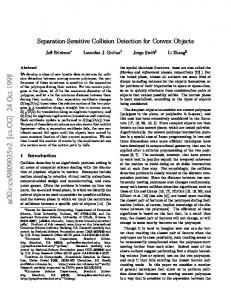
UNDERWATER OBJECTS’ DETECTION SYSTEM CHOICE FOR HARBOR SURVEILLANCE PURPOSES ABSTRACT The paper presents an analysis of various hydrographic systems, in order to find the most suit‐ able set of equipment for hydroacoustic harbor surveillance system. Singe beam and multibeam echosounders, sweep systems, sidescan sonars, scanning sonars, interferometric sonars and underwater vehicles were analyzed in terms of their usefulness for mentioned purpose. The preferred hydroacoustic systems were chosen based on the analysis results. Key words: harbor surveillance system, hydroacoustic systems, hydrographic equipment.
INTRODUCTION The importance of maritime transport in the modern economy causes the strong need of ensuring an appropriate harbors’ security level. This includes an access control to the harbor areas, not only from land, but also from waterside. The second option may be really problematic. Surface vessels’ traffic is closely con‐ trolled; any suspected activity can be relatively easily detected. Successful under‐ water surveillance is much more difficult to achieve. Surveillance systems available on market are focused on the possibility of detecting a diver or underwater vehicle trespassing to the port area of. This, how‐ ever, does not guarantee complete protection from the threat from below a water 1 Hydrographic Support Squadron of the Polish Navy, Rondo Bitwy pod Oliwą Str., 81‐103 Gdynia,
Poland; email:
[email protected]
47
Karolina Zwolak
surface. For example, an object which may pose a threat (for example an impro‐ vised explosive device) can be placed at the bottom of the harbor basin from the deck of a vessel that has already entered the port. The potential impact of such an event is described in [4]. The concept of a harbor surveillance system, based on a comparison of sonographs obtained at different points of time was established in Polish Naval Academy [5]. This would allow detecting new objects of an unknown origin at the harbor basin bottom, which can be dangerous. The important stage of the system development is a choice of data gathering equipment. This requires the analysis of modern survey equipment capabilities and the conditions in which the developed system will work. Relatively small depths of harbor areas must be taken into account. The boundary between a shallow and deep water reservoir is not strictly defined. In the context of the paper the shallow water means a depth range of a few to about 20 meters. The paper presents an overview of the hydrographic survey systems in the context of their suitability for the detection of potentially dangerous objects in hy‐ droacoustic harbor surveillance system.
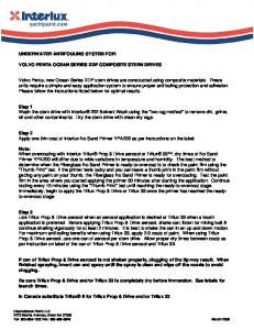
MULTIBEAM ECHOSOUNDERS Multibeam echosounders (MBES) recently dominated the modern hydro‐ graphy. The idea of this type of devices is based on a use of two orthogonally dis‐ posed transducers. The transmitting transducer generates an acoustic beam wide in the plane perpendicular to the direction measuring unit and narrow in a plane parallel to it. The receiving transducer, placed perpendicularly to the transmitting one can receive an acoustic signal reflected from the bottom within a narrow angle in a plane perpendicular to the survey line (fig. 1) [12]. A single acoustic beam is actually a ‘virtual’ beam formed by the emitter and receiver [6]. The use of carefully selected phase delays for individual transducer elements causes the effect of ‘sensi‐ tivity’ of the receiver for the signal reflected from a specific direction. A single set of delays applied to the signal received by the individual transducer elements gener‐ ates a depth value for the specified ‘virtual’ beam. Depending on the model, the echosounder generates from tens to hundreds of beams. With this configuration, the reception of a single acoustic pulse (after taking into account the information about the sound speed profile in the water column) results in obtaining a number 48
Zeszyty Naukowe AMW — Scientific Journal of PNA
Underwater objects’ detection system choice for harbor surveillance purposes
of depth values arranged approximately along a line perpendicular to the survey line. The exact layout of the soundings depends on the algorithms used for motion compensation [11].
Fig. 1. Multibeam echosounder principle Source: http://www.amloceanographic.com/CTDSoundVelocityEnvironmentalInstrumentation Home/MultibeamOvervew, [access 23.11. 2013].
A large number of soundings obtained from each acoustic pulse determine the high efficiency of multibeam data acquisition. Bathymetric data from multi‐ beam echosounder are characterized by high horizontal and vertical accuracy, mostly because of a use of motion compensation as well as a distribution of the sound speed in the process of depth calculation. Models available for measurement errors estimation, implemented in hydrographic software allows estimating values of uncertainties for depths obtained by multibeam echosounder [6]. Can be then MBES called ‘a perfect device’? First of all, because of an ad‐ vance technology and the system complexity, they are relatively expensive. There‐ fore they are not easily available for some institutions. In addition, MBES survey requires an access to the additional equipment for measuring the sound speed pro‐ files. Moreover, vessel motion parameters must be accurately measured, recorded and analyzed in the echosounder system in a real time. The sonar swath is a function of water depth; the lower the depth, the nar‐ rower area is ensonified during a single pass on the survey line. The use of a multibeam 1 (200) 2015
49
K Karolina Zwolak
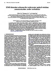
echosounderr in very shallo ow water in thiis situation is q questionable. T The risk of the expensive eq quipment damage at very sh hallow water m may be not balanced by the profit of survvey efficiency ccompared to th he single beam echosounder. Multiibeam echosou under is design ned for surveyying generally iin deeper wa‐ ters. Can it b be used for thee small objectss detection in sshallow waterss? The size of objects in rellation to the deensity of data p points is essenttial here. Figurre 2 shows a th hree‐dimension nal model creaated based on tthe bathymet‐ ric data obtained using Kon ngsberg EM204 40 multibeam echosounder, iin the Atlantic Ocean off thee coast of New Hampshire, USSA. Measuremeents were carriied out during the ‘Summerr Hydrography Field Course 2 2013’, the pracctical part of th he ‘Postgradu‐ ate Certificatte in Ocean batthymetry’ courrse under the ‘G GEBCO and Nip ppon Founda‐ tion Trainingg Project’. The survey was carried c out on the waters wiith a depth of approximateely 12 m. The area is used by b local fisherm men to catch lobsters l using traps, similarr to those show wn in figure 2. They are usu ually placed in straight lines. The metal strructure of such h a trap generates strong acou ustic echo. Thee length of this type of trap is generally hiigher than 1 m m, so they are q quite large in tthe context of objects, whicch should be deetectable by thee hydroacoustiic surveillance system. Figurre 2 presents regularly r arran nged objects, w which are cleaarly visible on the flat area of the sea bed d. In this case, a multibeam eechosounder eaasily detected objects on th he bottom. However, horizon ntal resolution n of multibeam m bathymetric data decreasses with increaasing depth, wh hile at shallow wer depths the use of multi‐ beam echoso ounder encoun nter difficultiess, as mentioned d above (low efficiency e and the risk of daamage).
Fig. 2. 3D seea bed visualization with 5‐times v vertical exaggeraation used; regulaarly arranged on the flat area of the sea bed objects aree clearly visible o Source: bathym metric data [7], piccture by author.
50
Zeszy yty Naukowe AM MW — Scientific Journal of PNA
Underwater o objects’ detectio on system choicce for harbor su urveillance purp poses
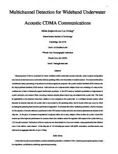
SIINGLE BEAM E ECHOSOUNDERS Singlle beam echossounders are the t most comm mon hydroaco oustic devices used for bath hymetric meassurements. Theey are availablle in different types. One of the most imp portant charactteristic is a beaam width, whicch is wide in aff ffordable ama‐ teur fishing echosounders and navigatio on equipment and gets narro ow in precise hydrographicc sonar (replacced by multibeeam echosound ders, with reseervations pre‐ viously discu ussed). In som me sources, oceanographic o or special purpose echo‐ sounders aree mentioned ass a separate typ pe of echosounders [10]. If a vvessel is not eq quipped with m motion parameeters registration system, an impact of roll and heave maay be significan nt in case of naarrow beam. In most cases, it is considered d that the roll angle is compensated by thee beam width, which is true for most naviigational echosounders, but raather not for su urvey equipmen nt (fig. 3a) [6]. a)
b)
Fig. 3. The correspon ndence between b beam width and transducer roll im mpact: a) roll is compensated by beeam width, b) the difference betweeen measured and true depth is caused by rroll impact not co ompensated by beam width [6]
Singlle beam echoso ounder does n not allow to deetermine the exxact direction of the reflectted acoustic waave; therefore, it is not possible to determiine if the indi‐ cated. Depth value correspo onds with the p point directly b below the transducer. Single beam echoso ounder, by acoustic wave two o way travel tiime measurem ment, indicates only the smaallest depth witthin an emitted beam. The d device operatess in some way a lowpass fillter, not record ding deeper arreas within an n acoustic footp print [6]. It is not a problem m from a navigational point of view becau use the shallow w areas detec‐ tion is essenttial. However, tthe device’s prrinciple of operration does nott allow detect‐ ing small objects on the botttom.
1 (200) 2015
51
Karolina Zwolak
SWEEP SYSTEMS The problem of low efficiency of hydrographic measurements in shallow waters has been addressed by the introduction of the so‐called sweep systems. They are series of single beam echo sounders placed on a structure perpendicular to the movement direction of the survey vessel. While such a solution provides a large swath width regardless of depth, the assumptions of the system generate a lot of problems. First of all, this system re‐ quires an installation of a structure to mount echosounders, which significantly impedes the maneuverability and makes the vessel very sensitive to higher sea states. In addition, the fact that a single echosounder records the smallest depth within its footprint, can lead to a situation in which several adjacent sonars actually captures the same depth, which makes the results very difficult to interpret.
Fig. 4. Sweep system’s principle Source: http://www.km.kongsberg.com/ks/web/nokbg0240.nsf/AllWeb/531E2BBCC30DDDD4C1256 DFA004CBB1D?OpenDocument.
SIDE SCAN SONARS Some geologists and geophysicists consider an opinion that the side scan sonars are no longer necessary, since there are multibeam echosounders available. Side scan sonar data used to evaluate the bottom type can be replaced by the back‐ scatter level from multibeam echosounders, providing also the bathymetric data. Does such an opinion can be shared by a hydrographer, whose main purpose is to detect obstacles to navigation or small objects on the bottom of the harbor basin? The requirements of the American National Ocean Service [13] suggest side scan sonar survey with 100% or 200% coverage, in addition to the multibeam 52
Zeszyty Naukowe AMW — Scientific Journal of PNA
Underwater o objects’ detectio on system choicce for harbor su urveillance purp poses
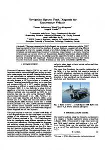
bathymetric measurementss. Side scan so onar takes an aadvantage from m optimal sig‐ nal geometryy, obtained because of the proper p sonar h height above th he sea bed. It also providess a high‐resolu ution data increeasing a probab bility of detecting objects on the sea bed. This type of data d is particu ularly valuable during bathym metric survey with single b beam echosoun nder, providin ng information about the botttom between survey lines. It can also bee used in addition to multibeeam survey to v verify data or for object ideentification [13 3]. The sspecificity of sid de scan sonar ssurveying is desscribed in detaiil in numerous publications.. Mosaicing pro ocess is presen nted in [2]. Sid de scan sonar ttests in a har‐ bor basin, in n an unusual configuration c w were presenteed in [9]. Sonaar was fixedly attached to th he hull of the v vessel. Considering quite shalllow depths, th he geometry of the system w was acceptable, despite the liimited possibillities of adjustiing the height of the sonar above the bottom. The resu ults presented d in this publiccation are the evidence of a possibility of o successful use u of side scaan sonar in shaallow, limited waters of docck areas. Figurre 5 shows exaamples of the so onar images ob btained in the aarea of Gdynia marina usingg towed side sccan sonar EdgeTech 272‐TD. Because of hiigh resolution of obtained im mages and a presence of acoustic shadows,, carrying inforrmation about the shapes o of objects, sidescan sonar seeems to be a prreferable devicce for sea bed objects detecction.
a)
b)
c) Fig. 5. Examples of side sscan sonar: a) pieer construction elements in Gdyniaa marina, b) buoy aan chor, c) an objeect close to the brreakwater
1 (200) 2015
53
Karolina Zwolak
INTERFEROMETRIC SONARS Interferometric sonar is a device combining the advantages of sidescan so‐ nar (obtaining high‐resolution sonographs) with the ability to measure depths, providing data in some way comparable with multibeam echosounder measure‐ ments. The phenomenon of interferometry (measuring the phase difference of sig‐ nals received by a series of three parallel arranged transducers) is used in this kind of equipment. An example of the interferometric sonar (Hydrochart‐3500 from L3) is shown in figure 6.
a)
b) Fig. 6. Interferometric sonar Hydrochart-3500 onshore (a) and on the vessel bow frame (b)
Reliable measurements of depth values exclude the possibility of towing sonar behind a vessel. It is necessary to attach the device to a hull, which in case of larger water depths may cause the poor signal geometry. Use of the construction which allows making adjustments of the sonar draft (similar to this presented in fig. 6b) enables enhancing system geometry. It may not be sufficient in shallow waters, but the adjustment range is still smaller than in the case of towed sonar. The use of interferometric sonar for small objects detection (or use it as a side sonar) is objectionable because of the limited possibility of ensuring sonar optimum height above the bottom. However, from the point of view of data acquisi‐ tion for scientific purposes, the possibility of obtaining various data types using a compact unit is extremely valuable. Interferometry technique is still being developed. Interferometric devices provide more and more accurate bathymetric measure‐ ments combined with the acquisition of sonograms, which probably will strengthen the position of the interferometric sonars in near future.
54
Zeszyty Naukowe AMW — Scientific Journal of PNA
Underwater objects’ detection system choice for harbor surveillance purposes
SCANNING SONARS The principle of operation of scanning sonars is similar to the sidescan sonars, but its design, based on a rotating acoustic transducer, gives radar‐like looking sonographs. The whole device does not move during measurement, excluding ro‐ tating transducer array. Examples of data obtained by scanning sonar can be found in [3]. High‐frequency scanning sonar, working on relatively small ranges, allows obtaining very high resolution images, which can be used for objects identification. Lower surveying efficiency, caused by the fact that scanning is performed in one stationary point at one time, speaks for choosing rather towed sidescan sonar, as a prime data acquisition device in the hydroacoustic harbor surveillance system.
UNDERWATER VEHICLES Underwater vehicles in modern hydrography perform a number of func‐ tions. The traditional classification distinguishes two main groups of underwater vehicles: • AUVs (Autonomous Underwater Vehicles) — carrying out programmed func‐ tions without operator intervention; • ROVs (Remotely Operated Vehicles) — submersible vehicles externally powered and controlled by an operator from the onshore or a vessel. In [1] UUVs (Unmanned Untethered Vehicles) are listed as a third category of underwater vehicles. They are characterized by its own power supply, but re‐ quiring operator intervention during the execution of the task. Other sources, how‐ ever, treat the UUVs as a wide a group of underwater vehicles, especially in military applications, explaining the abbreviation as Unmanned Underwater Vehicles. This division takes into account mainly the method of control during an op‐ eration. Classification according to the implemented functions may be not so clear. Underwater vehicle can be understood as a carrier for data acquisition devices. The change of installed devices is available in some models, and thus the change of functions. A modular underwater vehicle GAVIA can be an example. It can be alter‐ natively equipped for example with sidescan sonar, interferometric sonar or sub bottom profiler [8].
1 (200) 2015
55
Karolina Zwolak
Underwater vehicles, depending on their technical characteristics, can be used in various depth ranges, from shallow waters to the depths of the oceans. Kaiko 7000II from Japan Agency for Marine‐Earth Science and Technology (JAMSTEC) is dedicated to work at depths of up to 7000 m. In the testing phase in 1995, at the Challenger Deep, Kaiko dived to a depth of 10 911.4 m [14]. However, from the surveillance system point of view, installed devices, not the high operation depth, is crucial for the system choice decision. Underwater vehicle equipped with high‐resolution sidescan sonar and pre‐ cise navigation system could be used in hydroacoustic harbor surveillance system for images acquisition and subsequent detection of potentially dangerous objects. However, the methodology of underwater vehicle use in surveillance harbor sys‐ tem must be elaborated. Underwater vehicles are usually equipped with a camera, which provides a perfect solution for flawless object identification, but its range (depending on the optical properties of water) is usually significantly smaller than the range of hy‐ droacoustic device.
SUMMARY Side scan sonar is chosen as a preferred data acquisition system for hy‐ droacoustic surveillance system purposes. It should maximize the possibility of object detection on the bottom of controlled harbor area. The geometry of the sys‐ tem ensures the optimal acoustic beam use, dedicated to obtaining sonographs, ensuring the possibility of object detection and recognition. Scanning sonar and underwater vehicle may be used as tools for detected object identification, creating a complete hydroacoustic surveillance system.
REFERENCES [1]
Blidberg D. R., The development of autonomous underwater vehicles (AUVs); a brief summary, IEEE ICRA, 2001.
[2]
Chorzewska K., Mozaikowanie obrazów sonarowych wykonanych urządzeniami holowanymi / Side scan sonar image mosaicing [bilingual], ‘Zeszyty Naukowe Akademii Marynarki Wo‐ jennej, 2013, No. 4.
[3]
Chorzewska K., Wykorzystanie sonaru opuszczanego na przykładzie sonaru hydrograficznego MS 1000, ‘Forum Nawigacji’, 2009, No. 1 [Variable depth sonar application on the example of hydrografic sonar MS 1000 — available in the Polish language].
56
Zeszyty Naukowe AMW — Scientific Journal of PNA
Underwater objects’ detection system choice for harbor surveillance purposes [4]
Chorzewska K., Szulc D., Cichocki A., Prowizoryczne ładunki wybuchowe jako zagrożenie dla jednostek w portach morskich, ‘Logistyka’, 2009, No. 3 [Imrovised Explosive Devices as a threat for vesels in harbors — available in the Polish language].
[5]
Cywinski A., Szulc D., Ochrona portu morskiego. Struktura i zadania centrum monitoringu, ‘Logistyka’, 2009, No 3 [Harbor protection. The structure and tasks of monitoring center — available in the Polish language].
[6]
Dijkstra S., Armstrong A., Mayer L., Fundamentals of Ocean Mapping course notes, Center for Coastal and Ocean Mapping/Joint Hydrographic Center, University of New Hampshire, 2013.
[7]
Dijkstra S., Armstrong A., Mayer L., Summer Hydrography Field Course notes, Center for Coastal and Ocean Mapping/Joint Hydrographic Center, University of New Hampshire, 28.05.2013–12.07.2013.
[8]
Gavia, Payloads and Options, [online], http://www.teledynegavia.com/index.php/product_ dashboard/payloads_options, [access 11.11.2014].
[9]
Grządziel A., Felski A., Optymalizacja techniki użycia systemu sonarowego do realizacji po miarów w basenie portowym, ‘Logistyka’, 2012, No. 3 [Optimization of the sonar system usage for survey performed in harbour basin — available in the Polish language].
[10] Gucma M., Montewka J., Zieziula A., Urządzenia nawigacji technicznej, Fundacja Rozwoju Akademii Morskiej w Szczecinie, Szczecin 2005 [Technical navigation devices — available in the Polish language]. [11] Hughes Clarke J. E., Are you really getting ‘full bottom coverage’?, [online], http://www.omg.unb.ca/~jhc/coverage_paper.html, [access 23.11.2013]. [12] L3 Communications SeaBeam Instruments, Multibeam Sonar Theory of Operation, [online], http://www.ldeo.columbia.edu/res/pi/MB‐System/sonarfunction/SeaBeamMultibeam TheoryOperation.pdf, [access 23.11.2013]. [13] NOS Hydrographic Surveys Specifications And Deliverables, National Oceanic and Atmospheric Administration, U.S. Department of Commerce, 2014, [online], http://www.nauticalcharts. noaa.gov/hsd/specs/SPECS_2014.pdf, [access 11.11.2014]. [14] 7,000 m Class Remotely Operated Vehicle KAIKO 7000II, [online], http://www.jamstec. go.jp/e/about/equipment/ships/kaiko7000.html, [access 11.11.2014].
WYBÓR SYSTEMU DETEKCJI OBIEKTÓW PODWODNYCH DLA POTRZEB HYDROAKUSTYCZNEGO S YS T E M U K ON T R OL I D N A A KW E N Ó W P OR T O W Y C H STRESZCZENIE W artykule przedstawiono analizę różnorodnych systemów hydrograficznych pod kątem możli‐ wości ich wykorzystania w hydroakustycznym systemie kontroli dna akwenów portowych. Ana‐ liza obejmuje echosondy jedno‐ i wielowiązkowe, systemy wieloprzetwornikowe, sonary boczne
1 (200) 2015
57
Karolina Zwolak i skanujące, sonary interferometryczne oraz pojazdy podwodne. W oparciu o ich charakterystykę i sposób użycia wskazano systemy hydroakustyczne preferowane do detekcji obiektów w ramach kontroli dna akwenów portowych. Słowa kluczowe: ochrona portu morskiego, systemy hydrograficzne, urządzenia hydrograficzne.
58
Zeszyty Naukowe AMW — Scientific Journal of PNA